US4449657A - Auto luggage carrier - Google Patents
Auto luggage carrier Download PDFInfo
- Publication number
- US4449657A US4449657A US06/400,463 US40046382A US4449657A US 4449657 A US4449657 A US 4449657A US 40046382 A US40046382 A US 40046382A US 4449657 A US4449657 A US 4449657A
- Authority
- US
- United States
- Prior art keywords
- vehicle
- bracket
- auto
- post
- luggage carrier
- Prior art date
- Legal status (The legal status is an assumption and is not a legal conclusion. Google has not performed a legal analysis and makes no representation as to the accuracy of the status listed.)
- Expired - Fee Related
Links
- 230000009977 dual effect Effects 0.000 claims 2
- 238000012986 modification Methods 0.000 claims 1
- 230000004048 modification Effects 0.000 claims 1
- 230000000284 resting effect Effects 0.000 description 2
- 238000005299 abrasion Methods 0.000 description 1
- 239000000969 carrier Substances 0.000 description 1
- 238000009434 installation Methods 0.000 description 1
Images
Classifications
-
- B—PERFORMING OPERATIONS; TRANSPORTING
- B60—VEHICLES IN GENERAL
- B60R—VEHICLES, VEHICLE FITTINGS, OR VEHICLE PARTS, NOT OTHERWISE PROVIDED FOR
- B60R9/00—Supplementary fittings on vehicle exterior for carrying loads, e.g. luggage, sports gear or the like
- B60R9/04—Carriers associated with vehicle roof
- B60R9/058—Carriers associated with vehicle roof characterised by releasable attaching means between carrier and roof
Definitions
- This invention relates to auto luggage carriers of the type that are positioned on the roof of a vehicle and on which luggage or other cargo is secured.
- a luggage rack for an auto having a foot which supports the rack and rests on the vehicle's top independent of clamps that secure the rack and foot to the vehicle's top.
- a seat support is disclosed on a vehicle's top with a pair of main support bars resting on vertical support members and secured by a threaded rod clamp adjacent its ends.
- U.S. Pat. No. 2,436,228 is a luggage carrier having an adjustable support rack resting on foot members on the vehicle's roof with separate clamping means for securing the same to the vehicle.
- Applicant's device utilizes a cross bar secured to the vehicle by a load supporting vertically adjustable members which not only supports the load of the cross bar, but secures the cross bar to the vehicles roof by extending through a vertical support member attached to the ends of the bars and to the vehicle.
- An auto luggage carrier for use on the roof of a vehicle to secure luggage or other cargo thereto.
- the luggage carrier is comprised of multiple support units, each having a bar extending transversely across the vehicle's top and secured to a gutter portion of the top. Each unit is secured at opposite ends by a combination of an adjustable vertical load support member and an apertured bracket that clamps the carrier securely to the gutter. Tie down members are threadably secured to the ends of the bars to provide secure tie down points for the carrier.
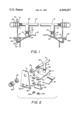
- FIG. 1 is an elevational view of the luggage carrier mounted on a vehicle roof
- FIG. 2 is an exploded view of a portion of the luggage carrier.
- An auto luggage carrier as seen in FIGS. 1 and 2 of the drawings, comprises a pair of support units, each one comprising a bar 10 threaded on its opposite ends.
- a multiple apertured bracket 11 is positioned on the opposite ends of the bar 10 and is held in place by a pair of threaded nuts 12 positioned on the bar 10 on opposite sides of the apertured bracket 11 through which the bar 10 passes.
- a rectangular bracket 13 is bifurcated at one end forming tabs 15 which register within apertures 15A in said bracket 13. Each of the tabs 15 is apertured inwardly from its ends to accept fasteners 16 therethrough. The other end of the rectangular bracket 13 is formed as at 17 to match the contour of a vehicle's roof 18.
- a threaded post 19 is secured to the formed portion 17 of the apertured bracket 11 and has a threaded nut 20 thereon.
- a sleeve 21 has a U-shaped notch 22 transversely across one end and is positioned over the post 19 abutting the nut 20.
- a clamping member 23 has a pair of oppositely disposed flanges 24 and 25 which abut the bifurcated tabs 15 and the vehicle's top 18 respectively.
- the flange 24 is apertured at 25a through which the fasteners 16 pass securing the apertured bracket 11 and the rectangular bracket 13 to the vehicle's roof 18.
- the flange 25 is curved to conform with and engage under a gutter portion 27 of the vehicle's top 18.
- the apertured bracket 11 has a curved flange 28 along its bottom edge which engages the top of the gutter 27.
- a resilient pad 30 of a shape and size equal to that of the end portion 17 of the rectangular member 13 is positioned under said portion 17 effectively protecting the vehicle's top 18 from abrasion.
- the completed assembly is easily adjusted to conform with different vehicle top configurations and widths with ease of installation and providing an adjustable stable support system for carrying a variety of different sized articles.
Landscapes
- Engineering & Computer Science (AREA)
- Mechanical Engineering (AREA)
- Fittings On The Vehicle Exterior For Carrying Loads, And Devices For Holding Or Mounting Articles (AREA)
Abstract
An auto luggage carrier comprising multiple support units, each of which having a cross bar secured to the vehicle at its respective ends. Vertically adjustable load supports adjacent the units ends match the vehicles top configuration and secure the support units to the vehicle.
Description
(1) Technical Field
This invention relates to auto luggage carriers of the type that are positioned on the roof of a vehicle and on which luggage or other cargo is secured.
(2) Description of the Prior Art
Prior art devices of this type have relied on a variety of different designs. See for example U.S. Pat. Nos. 2,574,018, 2,853,119, 2,436,228 and 3,109,569.
In U.S. Pat. No. 2,574,108, a luggage rack for an auto is disclosed having a foot which supports the rack and rests on the vehicle's top independent of clamps that secure the rack and foot to the vehicle's top.
In U.S. Pat. No. 2,853,119 a seat support is disclosed on a vehicle's top with a pair of main support bars resting on vertical support members and secured by a threaded rod clamp adjacent its ends.
U.S. Pat. No. 2,436,228 is a luggage carrier having an adjustable support rack resting on foot members on the vehicle's roof with separate clamping means for securing the same to the vehicle.
Finally, in U.S. Pat. No. 1,309,569, a car top carrier is disclosed wherein a pair of spaced luggage bars are supported on the vehicle's top by a pivoted bracket from which extends a turn buckle type clamp securing the rack to the vehicle.
Applicant's device utilizes a cross bar secured to the vehicle by a load supporting vertically adjustable members which not only supports the load of the cross bar, but secures the cross bar to the vehicles roof by extending through a vertical support member attached to the ends of the bars and to the vehicle.
An auto luggage carrier for use on the roof of a vehicle to secure luggage or other cargo thereto. The luggage carrier is comprised of multiple support units, each having a bar extending transversely across the vehicle's top and secured to a gutter portion of the top. Each unit is secured at opposite ends by a combination of an adjustable vertical load support member and an apertured bracket that clamps the carrier securely to the gutter. Tie down members are threadably secured to the ends of the bars to provide secure tie down points for the carrier.
FIG. 1 is an elevational view of the luggage carrier mounted on a vehicle roof; and
FIG. 2 is an exploded view of a portion of the luggage carrier.
An auto luggage carrier as seen in FIGS. 1 and 2 of the drawings, comprises a pair of support units, each one comprising a bar 10 threaded on its opposite ends. A multiple apertured bracket 11 is positioned on the opposite ends of the bar 10 and is held in place by a pair of threaded nuts 12 positioned on the bar 10 on opposite sides of the apertured bracket 11 through which the bar 10 passes.
A rectangular bracket 13 is bifurcated at one end forming tabs 15 which register within apertures 15A in said bracket 13. Each of the tabs 15 is apertured inwardly from its ends to accept fasteners 16 therethrough. The other end of the rectangular bracket 13 is formed as at 17 to match the contour of a vehicle's roof 18. A threaded post 19 is secured to the formed portion 17 of the apertured bracket 11 and has a threaded nut 20 thereon. A sleeve 21 has a U-shaped notch 22 transversely across one end and is positioned over the post 19 abutting the nut 20.
It will be seen that by rotating the nut 20, the sleeve 21 will move accordingly engaging the bar 10 within the U-shaped notch 22 so as to allow for vertical adjustment of the apertured bracket 11 in relation to the bar 10. A clamping member 23 has a pair of oppositely disposed flanges 24 and 25 which abut the bifurcated tabs 15 and the vehicle's top 18 respectively. The flange 24 is apertured at 25a through which the fasteners 16 pass securing the apertured bracket 11 and the rectangular bracket 13 to the vehicle's roof 18.
The flange 25 is curved to conform with and engage under a gutter portion 27 of the vehicle's top 18. The apertured bracket 11 has a curved flange 28 along its bottom edge which engages the top of the gutter 27.
It will be seen that the fastener 16 with the nut 16A secure the clamping member 23 to the tabs 15 which pass through the apertured bracket 11 effectively clamping the assembly to the gutter portion 27 as best seen in FIG. 1 of the drawings. Once in place, U-shaped threaded members 29 are threaded on the ends of the bar 10 providing tie-down points to secure the load to multiple support units on the vehicle's top.
A resilient pad 30 of a shape and size equal to that of the end portion 17 of the rectangular member 13 is positioned under said portion 17 effectively protecting the vehicle's top 18 from abrasion.
The completed assembly is easily adjusted to conform with different vehicle top configurations and widths with ease of installation and providing an adjustable stable support system for carrying a variety of different sized articles.
Claims (5)
1. An auto luggage carrier for mounting on the roof of a vehicle, said carrier having multiple support units, each unit comprising at least one bar positioned transversely of said vehicle's roof, dual means for adjustably supporting said bar on said vehicle, threaded end portions on said ends of said bars, a pair of spaced threaded nuts on said threaded end, an apertured bracket secured to said bar between said spaced nuts and extending to the roof of said vehicle, a post having threads adjacent an end, a sleeve movably positioned on said post, a bifurcated bracket secured to said post and removably secured to said apertured bracket, means for securing said apertured bracket and said bracket to a vehicle's top and wherein said dual means for adjustably supporting said bar are spaced with respect to one another.
2. The auto luggage carrier of claim 1 wherein said apertured bracket has a curved flange along its lower edge.
3. The auto luggage carrier of claim 1 wherein said means for securing said apertured bracket and said bracket to said vehicle's top comprises a clamping member having oppositely disposed flanges, one of which is apertured to receive fasteners therethrough.
4. The auto luggage carrier of claim 1 wherein a portion of said bracket to which said post is secured is contoured to said vehicle's top and a resilient pad is positioned between said contoured portion of said bracket and the vehicle's top.
5. The auto luggage carrier of claim 1 wherein said sleeve has a U-shaped notch transversely across one end positioned over said post abutting a nut on said post.
Priority Applications (1)
| Application Number | Priority Date | Filing Date | Title |
|---|---|---|---|
| US06/400,463 US4449657A (en) | 1982-07-21 | 1982-07-21 | Auto luggage carrier |
Applications Claiming Priority (1)
| Application Number | Priority Date | Filing Date | Title |
|---|---|---|---|
| US06/400,463 US4449657A (en) | 1982-07-21 | 1982-07-21 | Auto luggage carrier |
Publications (1)
| Publication Number | Publication Date |
|---|---|
| US4449657A true US4449657A (en) | 1984-05-22 |
Family
ID=23583719
Family Applications (1)
| Application Number | Title | Priority Date | Filing Date |
|---|---|---|---|
| US06/400,463 Expired - Fee Related US4449657A (en) | 1982-07-21 | 1982-07-21 | Auto luggage carrier |
Country Status (1)
| Country | Link |
|---|---|
| US (1) | US4449657A (en) |
Cited By (1)
| Publication number | Priority date | Publication date | Assignee | Title |
|---|---|---|---|---|
| US6530621B1 (en) * | 2000-07-19 | 2003-03-11 | Ford Global Technologies, Inc. | Vehicle convertible track system |
Citations (4)
| Publication number | Priority date | Publication date | Assignee | Title |
|---|---|---|---|---|
| US3064868A (en) * | 1960-01-25 | 1962-11-20 | Quick N Easy Products Ltd | Adjustable strut for cargo carrier |
| US3174536A (en) * | 1961-02-14 | 1965-03-23 | John P Francis | Frame supporting means for automobile windshield awning |
| US3381866A (en) * | 1966-12-01 | 1968-05-07 | Charles E. Wickett | Detachable luggage rack |
| US4101061A (en) * | 1977-05-09 | 1978-07-18 | U-Haul International, Inc. | Adjustable car top carrier support |
-
1982
- 1982-07-21 US US06/400,463 patent/US4449657A/en not_active Expired - Fee Related
Patent Citations (4)
| Publication number | Priority date | Publication date | Assignee | Title |
|---|---|---|---|---|
| US3064868A (en) * | 1960-01-25 | 1962-11-20 | Quick N Easy Products Ltd | Adjustable strut for cargo carrier |
| US3174536A (en) * | 1961-02-14 | 1965-03-23 | John P Francis | Frame supporting means for automobile windshield awning |
| US3381866A (en) * | 1966-12-01 | 1968-05-07 | Charles E. Wickett | Detachable luggage rack |
| US4101061A (en) * | 1977-05-09 | 1978-07-18 | U-Haul International, Inc. | Adjustable car top carrier support |
Cited By (1)
| Publication number | Priority date | Publication date | Assignee | Title |
|---|---|---|---|---|
| US6530621B1 (en) * | 2000-07-19 | 2003-03-11 | Ford Global Technologies, Inc. | Vehicle convertible track system |
Similar Documents
| Publication | Publication Date | Title |
|---|---|---|
| US3931919A (en) | Bicycle carrier for automobiles | |
| US2663472A (en) | Cargo carrier for motor vehicles | |
| US5314104A (en) | Auto mount for bicycle rack | |
| US5085360A (en) | Spare tire mounted bicycle rack | |
| US5065921A (en) | Bicycle rack for mounting on a van | |
| US4085874A (en) | Automobile bicycle carrier | |
| US4461410A (en) | Automobile bicycle carrying rack | |
| US4089448A (en) | Bicycle-ski rack for automobiles | |
| EP0941915B1 (en) | Wheel axle suspension for a vehicle with a gas spring system | |
| US4483471A (en) | Cargo carrier | |
| SE9500430L (en) | load carriers | |
| US5201911A (en) | Mount for bicycle rack | |
| US4022362A (en) | Bicycle carrier | |
| US4382532A (en) | Fastening device for a roof rack for luggage | |
| US3367548A (en) | Front carrier for motorcycle | |
| KR20180134414A (en) | Mounting assembly and mud guard assembly for mounting the mud guard | |
| US3381866A (en) | Detachable luggage rack | |
| US4449657A (en) | Auto luggage carrier | |
| US3731967A (en) | Roof walkway for truck cabs | |
| US7040846B2 (en) | Transit bracket assembly for motorcycles | |
| US4537338A (en) | Baggage carrier for two-wheeled vehicles | |
| US7845597B2 (en) | Conduit carrier system | |
| US3275206A (en) | Sports cycle carriers | |
| US5219106A (en) | Game carrier for a vehicle | |
| US2641396A (en) | Luggage carrier for vehicles |
Legal Events
| Date | Code | Title | Description |
|---|---|---|---|
| REMI | Maintenance fee reminder mailed | ||
| LAPS | Lapse for failure to pay maintenance fees | ||
| STCH | Information on status: patent discontinuation |
Free format text: PATENT EXPIRED DUE TO NONPAYMENT OF MAINTENANCE FEES UNDER 37 CFR 1.362 |
|
| FP | Lapsed due to failure to pay maintenance fee |
Effective date: 19880522 |