US4438072A - Continuous stream mixer having variable dwell time chamber with auger - Google Patents
Continuous stream mixer having variable dwell time chamber with auger Download PDFInfo
- Publication number
- US4438072A US4438072A US06/350,861 US35086182A US4438072A US 4438072 A US4438072 A US 4438072A US 35086182 A US35086182 A US 35086182A US 4438072 A US4438072 A US 4438072A
- Authority
- US
- United States
- Prior art keywords
- mixing
- auger
- dwell chamber
- coupled
- pipe
- Prior art date
- Legal status (The legal status is an assumption and is not a legal conclusion. Google has not performed a legal analysis and makes no representation as to the accuracy of the status listed.)
- Expired - Fee Related
Links
- 238000002156 mixing Methods 0.000 claims abstract description 66
- 239000000463 material Substances 0.000 claims description 49
- 239000000376 reactant Substances 0.000 claims description 14
- 230000008878 coupling Effects 0.000 claims description 7
- 238000010168 coupling process Methods 0.000 claims description 7
- 238000005859 coupling reaction Methods 0.000 claims description 7
- 230000003068 static effect Effects 0.000 claims description 7
- 230000037361 pathway Effects 0.000 claims 4
- 238000005086 pumping Methods 0.000 claims 2
- 239000002184 metal Substances 0.000 claims 1
- 230000036962 time dependent Effects 0.000 claims 1
- 238000005406 washing Methods 0.000 abstract description 3
- LYCAIKOWRPUZTN-UHFFFAOYSA-N Ethylene glycol Chemical compound OCCO LYCAIKOWRPUZTN-UHFFFAOYSA-N 0.000 description 24
- 239000000499 gel Substances 0.000 description 16
- 239000000047 product Substances 0.000 description 13
- WGCNASOHLSPBMP-UHFFFAOYSA-N hydroxyacetaldehyde Natural products OCC=O WGCNASOHLSPBMP-UHFFFAOYSA-N 0.000 description 12
- 239000000126 substance Substances 0.000 description 9
- 239000007788 liquid Substances 0.000 description 8
- 239000012948 isocyanate Substances 0.000 description 5
- 239000007864 aqueous solution Substances 0.000 description 4
- 238000004140 cleaning Methods 0.000 description 4
- 150000002009 diols Chemical class 0.000 description 4
- 239000000839 emulsion Substances 0.000 description 4
- 239000004814 polyurethane Substances 0.000 description 4
- 229920002635 polyurethane Polymers 0.000 description 4
- 229910001220 stainless steel Inorganic materials 0.000 description 4
- 239000010935 stainless steel Substances 0.000 description 4
- XLYOFNOQVPJJNP-UHFFFAOYSA-N water Substances O XLYOFNOQVPJJNP-UHFFFAOYSA-N 0.000 description 4
- 238000011010 flushing procedure Methods 0.000 description 3
- IAYPIBMASNFSPL-UHFFFAOYSA-N Ethylene oxide Chemical class C1CO1 IAYPIBMASNFSPL-UHFFFAOYSA-N 0.000 description 2
- PEDCQBHIVMGVHV-UHFFFAOYSA-N Glycerine Chemical compound OCC(O)CO PEDCQBHIVMGVHV-UHFFFAOYSA-N 0.000 description 2
- 239000004721 Polyphenylene oxide Substances 0.000 description 2
- 239000004809 Teflon Substances 0.000 description 2
- 229920006362 Teflon® Polymers 0.000 description 2
- XSTXAVWGXDQKEL-UHFFFAOYSA-N Trichloroethylene Chemical compound ClC=C(Cl)Cl XSTXAVWGXDQKEL-UHFFFAOYSA-N 0.000 description 2
- 239000000654 additive Substances 0.000 description 2
- 239000000945 filler Substances 0.000 description 2
- 239000012467 final product Substances 0.000 description 2
- 239000000203 mixture Substances 0.000 description 2
- 238000012856 packing Methods 0.000 description 2
- 229920000570 polyether Polymers 0.000 description 2
- 229920001228 polyisocyanate Polymers 0.000 description 2
- 239000005056 polyisocyanate Substances 0.000 description 2
- 229920005862 polyol Polymers 0.000 description 2
- 150000003077 polyols Chemical class 0.000 description 2
- 238000002360 preparation method Methods 0.000 description 2
- 239000007858 starting material Substances 0.000 description 2
- 238000003756 stirring Methods 0.000 description 2
- GOOHAUXETOMSMM-UHFFFAOYSA-N Propylene oxide Chemical compound CC1CO1 GOOHAUXETOMSMM-UHFFFAOYSA-N 0.000 description 1
- WYURNTSHIVDZCO-UHFFFAOYSA-N Tetrahydrofuran Chemical compound C1CCOC1 WYURNTSHIVDZCO-UHFFFAOYSA-N 0.000 description 1
- 230000035508 accumulation Effects 0.000 description 1
- 238000009825 accumulation Methods 0.000 description 1
- 238000009435 building construction Methods 0.000 description 1
- 239000003086 colorant Substances 0.000 description 1
- 239000004020 conductor Substances 0.000 description 1
- 238000010586 diagram Methods 0.000 description 1
- 238000007599 discharging Methods 0.000 description 1
- 239000011521 glass Substances 0.000 description 1
- 235000011187 glycerol Nutrition 0.000 description 1
- 239000007970 homogeneous dispersion Substances 0.000 description 1
- HLJDOURGTRAFHE-UHFFFAOYSA-N isocyanic acid;3,5,5-trimethylcyclohex-2-en-1-one Chemical compound N=C=O.N=C=O.CC1=CC(=O)CC(C)(C)C1 HLJDOURGTRAFHE-UHFFFAOYSA-N 0.000 description 1
- KCWDJXPPZHMEIK-UHFFFAOYSA-N isocyanic acid;toluene Chemical compound N=C=O.N=C=O.CC1=CC=CC=C1 KCWDJXPPZHMEIK-UHFFFAOYSA-N 0.000 description 1
- 238000004519 manufacturing process Methods 0.000 description 1
- 238000000034 method Methods 0.000 description 1
- 239000002245 particle Substances 0.000 description 1
- 239000002304 perfume Substances 0.000 description 1
- 230000009257 reactivity Effects 0.000 description 1
- 238000007790 scraping Methods 0.000 description 1
- 150000004072 triols Chemical class 0.000 description 1
- 239000002699 waste material Substances 0.000 description 1
Images
Classifications
-
- B—PERFORMING OPERATIONS; TRANSPORTING
- B29—WORKING OF PLASTICS; WORKING OF SUBSTANCES IN A PLASTIC STATE IN GENERAL
- B29B—PREPARATION OR PRETREATMENT OF THE MATERIAL TO BE SHAPED; MAKING GRANULES OR PREFORMS; RECOVERY OF PLASTICS OR OTHER CONSTITUENTS OF WASTE MATERIAL CONTAINING PLASTICS
- B29B7/00—Mixing; Kneading
- B29B7/30—Mixing; Kneading continuous, with mechanical mixing or kneading devices
- B29B7/34—Mixing; Kneading continuous, with mechanical mixing or kneading devices with movable mixing or kneading devices
- B29B7/38—Mixing; Kneading continuous, with mechanical mixing or kneading devices with movable mixing or kneading devices rotary
-
- B—PERFORMING OPERATIONS; TRANSPORTING
- B29—WORKING OF PLASTICS; WORKING OF SUBSTANCES IN A PLASTIC STATE IN GENERAL
- B29B—PREPARATION OR PRETREATMENT OF THE MATERIAL TO BE SHAPED; MAKING GRANULES OR PREFORMS; RECOVERY OF PLASTICS OR OTHER CONSTITUENTS OF WASTE MATERIAL CONTAINING PLASTICS
- B29B7/00—Mixing; Kneading
- B29B7/74—Mixing; Kneading using other mixers or combinations of mixers, e.g. of dissimilar mixers ; Plant
- B29B7/7476—Systems, i.e. flow charts or diagrams; Plants
- B29B7/7485—Systems, i.e. flow charts or diagrams; Plants with consecutive mixers, e.g. with premixing some of the components
Definitions
- This invention relates to a tandem, two-component mixer having an elongate dwell chamber.
- a reverse twist auger is located in the dwell chamber to provide continuous scraping of the dwell chamber wall and prevent a buildup of material therein. While the mixer of the present invention has a variety of uses, it is particularly well suited for the preparation of polyurethane gels filled with dispersed, discrete particles of aqueous solutions.
- Tandem, two-component mixers are known to the mixing art and some of such mixers include a dwell chamber between the two mixing heads.
- Such prior art machines do not, however, have the ability to deliver a continuous stream of product where the reactants mixed in the machine gel rapidily.
- Such prior art mixers also permit a buildup of reactive material on the walls of the dwell chamber.
- polyurethane gels formed by mixing a polyisocyanate prepolymer with an aqueous liquid.
- the prepolymer may be a prepolymer of an organic di-isocyanate and a polyether diol or triol, and the aqueous liquid may be water. Rapid mixing of the two components causes a gel to form and the final product desirably contains a homogeneous dispersion of discrete droplets throughout the gel.
- the final properties of such gels can be varied by the choice of starting materials and by the mixing techniques employed.
- the gel can have open or closed cells depending on these various factors and the nature of the cells can be adjusted by varying the solute in the aqueous solution.
- the aqueous solution may contain colors, perfumes, fire retardents, electrically conductive materials and the like.
- Gels such as those just described can be cast to a specific shape or can be formed in a mass for selected uses.
- the gels may also be extruded. Typical uses of such gels are in building construction, marking devices, prosthetic devices, medical devices, etc.
- Another object of the present invention is to provide a two component mixing apparatus which includes mixing and dwell capabilities.
- Yet another object of the present invention is to provide a mixing apparatus for two materials which also includes a provision for addition of a third material as a reactant or as a washing material.
- a still further object of the present invention is to provide a mixing apparatus having an efficient dwell chamber mixing system.
- a further object of the present invention is to provide a mixing apparatus which includes a dispensing valve capable of dispensing mixed reactants into one of two paths and which also includes means for cleaning said valve to prevent buildup of reacted materials therein.
- a tandem, two-component mixer includes a dwell chamber located between two mixing heads. Pumps, valves and flow gauges are provided for the two components to insure that the correct amounts of materials are reacted.
- a reverse twist auger is located within the dwell chamber, the auger insuring further mixing of the components and preventing a buildup of material in the dwell chamber. After product leaves the dwell chamber, it travels to a second mixing head and then enters a final valve. The latter is designed to permit the product to be dispensed through two paths and thus permits the entire system to be operated continuously.
- the apparatus is designed so that all sections which have been contacted by the mixed reactants may be thoroughly flushed with a cleaning liquid.
- the mixer of the present invention may be variously embodied and may be used with a variety of reactive systems, all of which will be more apparent upon reading the following detailed description of the preferred embodiment.
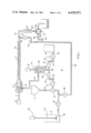
- FIG. 1 is a schematic diagram of a mixer of the preferred embodiment of the present invention
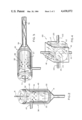
- FIG. 2 is an enlarged view of the first mixing head used with the mixer of the preferred embodiment of the present invention, with parts broken away to show detail;
- FIG. 3 is an enlarged view of a second mixing head used with the mixer of the preferred embodiment of the present invention, with parts broken away to show detail;
- FIG. 4 is an enlarged schematic of the dispensing valve used with the mixer of the preferred embodiment of the present invention.
- a mixer 10 is shown in FIG. 1 in generally schematic form.
- Three reservoirs are provided for the reactants and for a cleaning liquid.
- a first reservoir 12 is provided for the polyisocyanate prepolymer.
- Reservoir 12 may be a tank or other suitable container and in the preferred embodiment includes a collapsing diaphragm cover (not shown) to prevent air from contacting the prepolymer.
- the prepolymer may be a prepolymer of an organic di-isocyanate and a polyether diol or triol and preferably contains at least 40% by weight of ethylene oxide adducts.
- the di-isocyanate may be toluene di-isocyanate, isophorone di-isocyanate, polymethylenepolyphenylene-di-isocyanate, alaphatic di-isocyanates or related materials.
- the polyols are diols or triols formed by combining ethylene oxide with lower molecular weight diol such as glycerine or a glycol.
- the polyol may also contain some propylene oxide, butylene oxide or other alaphatic oxides as adducts.
- a second reservoir 14 contains an aqueous liquid such as water or water containing solutes.
- the third reservoir 16 contains a chainstopper or cleaning liquid, such as a glycol.
- the three reservoirs 12, 14, and 16 may be constructed from any suitable material, such as glass or stainless steel, and each includes an outlet coupled to the mixing system.
- the outlet from reservoir 12 is coupled to a tubular pipe 18 which in turn is coupled to a three way valve 20.
- An outlet of valve 20 is coupled to a pump 21 and then to a flow gauge 22.
- a short pipe 24 leads from the flow gauge 22 and includes a simple on/off valve 26 which is used to interrupt the flow of liquid through pipe 24 when desired.
- the outlet from valve 26 is a pipe 28. It is preferred that the various pipes mentioned in this description be constructed of stainless steel, but other materials, such as teflon lined pipes, may be used.
- the aqueous reactant leaves reservoir 14 through a pipe 30 and in turn passes through a simiar pump 31, flow gauge 32 connecting pipe 33 and on/off valve 34.
- the aqueous material leaving the on/off valve 34 also enters pipe 28.
- Pipe 28 includes a T outlet 36 through which the combined reactants pass into a first mixing head 38.
- Mixing head 38 is shown in greater detail in FIG. 2 to include a generally cylindrical, hollow body 40 having a funnel shaped bottom 41 coupled to pipe 36. Head 38 also includes an outlet 43 extending through the upper portion of its side wall.
- a second cylinder 45 is mounted within body 40, cylinder 45 having an open bottom 50 (facing toward pipe 36) and a closed top 52. The diameter of cylinder 45 is just slightly smaller than the internal diameter of body 40, whereby cylinder 45 is free to rotate therein.
- Cylinder 45 also includes a plurality of paddle bars 53 mounted within its lower half and a plurality of perforations 54 through its side wall and generally near the top of cylinder 45.
- a motor 60 is mounted generally above mixing head 38, the motor having a shaft 61 extending therefrom and being oriented along the axis of body 40 and cylinder 45.
- the shaft 61 enters the top of body 40 through suitable bearings and water tight packings (not shown in detail) and is affixed to the center of top 52 of cylinder 45.
- Motor 60 then is capable of rotating cylinder 55 within body 40.
- the combined reactants enter body 40 and flow upwardly into cylinder 45. Because that cylinder is rotating (rapidly and at high speed in the preferred embodiment), the reactants are intimately mixed by the action of the paddle bars 53 and as upward flow continues, are further mixed as the reactants flow outwardly through perforations 54.
- the speed of mixer 38 will depend on the amount of mixing required for the specific chemical system, but as an example an rpm within the range of 1000 to 5000 is preferred.
- Mixing head 65 is similar to mixing head 38 except that the inlet and outlet are reversed.
- Mixer 65 is illustrated in detail in FIG. 3.
- Mixer 65 includes a body 66, an internal cylinder 67 having perforations 68, and a funnel shaped outlet 69.
- Mixing head 65 also includes a motor 70 having a shaft 71 coupled thereto for rotating cylinder 67 to provide further mixing as the chemical substances move toward outlet 69.
- Shaft 71 is again sealed through the left of body 66 but in this case passes through cylinder 67 and extends to the outlet 69.
- mixing head 65 does not include the paddle bars such as were employed with mixing head 38.
- motor 70 is a low rpm motor, with speeds in the range of 100 to 500 rpm being preferred.
- suitable sealed bearings and packing are provided at the left end of mixing head 65 to permit rotation of shaft 71 and prevent leaks.
- a dwell chamber 75 is coupled to the outlet 69 of mixing head 65, chamber 75 constituting an elongate pipe, which again is preferably constructed of stainless steel or teflon lined piping.
- the length of chamber 75 is selected to produce a proper gel time for the chemical system used with mixer 10 and may range from 12 to 36 inches for polyurethane gel systems. It should also be apparent that the flow rate of the materials through the mixing apparatus will affect time of dwell.
- the prepolymer While though the first two mixing heads are designed to emulsify the prepolymer and aqueous materials, the prepolymer will still have a tendency to fall out of the emulsion and adhere to the side walls of the mixing apparatus. The longer the dwell time required for the chemical system, the greater this tendency will be. In the present invention, this tendency is overcome by incorporating a reverse twist auger 78 into the dwell chamber to continuously scrape the walls of the chamber. Auger 78 also imparts a continuous turbulence to the flow of the mixed stream. Auger 78 in the preferred embodiment is constructed from a ribbon of stainless steel and is coupled at one end to shaft 71 of motor 70.
- the ribbon is twisted to form the auger, with the twist being reversed several times along the auger length, for example about every three inches.
- the reverse twisting insures adequate turbulence and prevents the emulsion of the two starting materials from breaking up in the dwell chamber.
- Pipe 79 which may include an inlet for another component of the chemical system if desired or required. This inlet is shown in the drawings as pipe 80.
- the third component may be a chainstopper, such as the glycol previously mentioned and may or may not contain additives or fillers required to give the properties desired of the final product.
- the third component will be glycol and is stored in reservoir 16.
- Reservoir 16 may include a stirrer 82 coupled to a low rpm motor 84 by a shaft 85 if stirring of this component is desired. Such stirring may be essential if fillers or additives have a tendency to settle from the carrier liquid.
- This chainstopper is pumped from reservoir 16 by pump 87 and flows through a first on/off valve 88, a pipe 89 and a flow guage 90 towards the inlet pipe 80.
- a second on/off valve 92 may be provided intermediate the flow guage and coupling for a reason which will become apparent later in this description.
- a static mixer 95 is of conventional design.
- Product flowing from the static mixer 95 then proceeds to a complex valve assembly 100 which will be described shortly and which permits the product to be dispersed for use or to be discarded at the discretion of the machine operator.
- Dispensing occurs through outlet 101 and discharging occurs through pipe 102.
- Another inlet is provided to valve assembly 100, i.e. a connection directly with pipe 89 carring the chainstopper.
- Pipe 103 includes a flow gauge 104 and a timer valve 105.
- valve assembly 100 it will be of assistance in understanding this component if it is explained at the outset that it may be cleaned of reactive materials whether the reactive material is to be dispensed or discarded. This capability is important because if the dispensing head is shut down for a short time, even a time as short as 10 seconds, a partial gel within the dwell chamber 75 will occur. If the dispensing head is shut down for 10 to 30 seconds, the dwell chamber and the dispensing valve assembly 100 will become totally clogged.
- Valve assembly 100 is shown in FIG. 4 to include a body 110 having a cylindrical valve member 112 rotatably disposed therein.
- the valve member 112 has three passageways formed therein for the flow of material.
- the first passageway is a straight, elongate channel 113 which is arranged to couple the reactive material inlet from the static mixer 95 to outlet 101 (when in the position shown in FIG. 4).
- the second passageway 115 is curved and is coupled at one end to the glycol inlet 103. This passageway curves upwardly approximately 90° and generally rearwardly through the valve member 112 and terminates at the surface of member 112.
- the third passageway is curved channel 117 which in the illustrated orientation begins at the top of valve member 112 and at the rear thereof, curving down approximately 90° and terminating at the discard outlet 102.
- Coupling channel 118 lies outside of the valve body 110 and is generally U-shaped. This channel couples the outlet of channel 115 to the inlet of channel 117 when the valve is in the orientation of FIG. 4.
- the second coupling channel 120 is also on the outside of valve body 110 and extends generally horizontally along the right side of valve member 112. The forward end is coupled to the outlet of passageway 117. Discard line 102 is also coupled to channel 120.
- valve 100 in the illustrated orientation product flows directly through passageway 113 for dispensing, while a glycol path is established from pipe 103 through passageways 115, 118, 117, 120 to discard outlet 102. If the valve member 112 is rotated by 90°, in a clockwise direction, it will be appreciated that a direct line is established from the glycol inlet 103 to the discard pipe 102 through passageway 113. At the same time, a flow path is established for the product stream through passageway 115 from the product inlet pipe to the discard line through passageway 120. In this second mode, channel 113 is flushed while product mixture is being discarded.
- glycol flow to valve assembly 100 is controlled by the timer valve 105. Flushing must be continued for a time sufficient to cleanse the valve lines which contact the reactive mixtures, and it has been determined that a flush of 10 seconds is sufficient in most instances. Obviously, flushing of the valve 100 consumes glycol material and waste is avoided by employing the timer valve as shown in the Figures.
- valve 88 may be closed and valve 20 rotated to send the glycol through valve 20, pump 21, flow gauge 22 and through the remaining parts of the apparatus.
- the aqueous material flow can be interrupted during such flushing by closing valve 34.
- the glycol flow can be directed through pipe 89 and upwardly through the static mixer and dwell chamber 75 by appropriate control of the various valves of the system.
Landscapes
- Engineering & Computer Science (AREA)
- Mechanical Engineering (AREA)
- Processing And Handling Of Plastics And Other Materials For Molding In General (AREA)
Abstract
Description
Claims (8)
Priority Applications (1)
| Application Number | Priority Date | Filing Date | Title |
|---|---|---|---|
| US06/350,861 US4438072A (en) | 1982-02-22 | 1982-02-22 | Continuous stream mixer having variable dwell time chamber with auger |
Applications Claiming Priority (1)
| Application Number | Priority Date | Filing Date | Title |
|---|---|---|---|
| US06/350,861 US4438072A (en) | 1982-02-22 | 1982-02-22 | Continuous stream mixer having variable dwell time chamber with auger |
Publications (1)
| Publication Number | Publication Date |
|---|---|
| US4438072A true US4438072A (en) | 1984-03-20 |
Family
ID=23378514
Family Applications (1)
| Application Number | Title | Priority Date | Filing Date |
|---|---|---|---|
| US06/350,861 Expired - Fee Related US4438072A (en) | 1982-02-22 | 1982-02-22 | Continuous stream mixer having variable dwell time chamber with auger |
Country Status (1)
| Country | Link |
|---|---|
| US (1) | US4438072A (en) |
Cited By (13)
| Publication number | Priority date | Publication date | Assignee | Title |
|---|---|---|---|---|
| DE3516236A1 (en) * | 1984-05-08 | 1985-11-14 | Centralen Institut po chimičeska promišlenost, Sofia/Sofija | Device for preparing suspension fertilisers |
| DE3735951A1 (en) * | 1987-10-23 | 1989-05-03 | Dietrich Maurer | Process for preparing limewash in any concentration and quantity required, and appliance for carrying out the process |
| EP0337386A1 (en) * | 1988-04-12 | 1989-10-18 | Kanegafuchi Kagaku Kogyo Kabushiki Kaisha | Process for continuous mixing of a two-liquid curing type resin |
| WO1990014152A1 (en) * | 1989-05-15 | 1990-11-29 | John Orava | Improved mixing nozzle apparatus and method of use |
| US5330724A (en) * | 1993-01-04 | 1994-07-19 | Dow Corning Corporation | Apparatus for blending and dispensing foamable, curable organosiloxane compositions |
| US5444100A (en) * | 1991-02-22 | 1995-08-22 | Sanyo Electric Co., Ltd. | Method for the mixing of low-boiling foaming agent |
| US5814282A (en) * | 1997-01-15 | 1998-09-29 | Lohe; Hans | High surface intermeshing profile reactor |
| WO2003018287A3 (en) * | 2001-08-23 | 2003-08-28 | Polymaterials Ag | Methods and devices for producing homogenous mixtures and for producing and testing moulded bodies |
| US20050040386A1 (en) * | 2001-02-20 | 2005-02-24 | Fow-Sen Choa | Multiple quantum well broad spectrum gain medium and method for forming same |
| US20100218953A1 (en) * | 2007-06-19 | 2010-09-02 | Leleux Jerome | Use of a fluid composition with delayed cross-linking for holding a casing inside a drill hole and method for reinforcing a drill hole |
| CN102672844A (en) * | 2012-05-22 | 2012-09-19 | 高鼎精细化工(昆山)有限公司 | Equipment for producing TPU (thermoplastic polyurethane) by two-stage mixing |
| JP2014505585A (en) * | 2010-12-23 | 2014-03-06 | エボニック コーポレイション | Apparatus and method for producing emulsions |
| US20220380514A1 (en) * | 2016-09-30 | 2022-12-01 | Axalta Coating Systems Ip Co., Llc | Composition |
Citations (9)
| Publication number | Priority date | Publication date | Assignee | Title |
|---|---|---|---|---|
| US2939770A (en) | 1954-08-07 | 1960-06-07 | Noblee & Thorl G M B H | Reaction column for the continuous treatment of liquids |
| US3167531A (en) | 1962-01-24 | 1965-01-26 | Monsanto Co | Continuous process for the manufacture of bis(2-hydroxyethyl) terephthalate and low molecular weight polymers thereof |
| US3257173A (en) | 1960-08-23 | 1966-06-21 | Du Pont | Polymer finishing apparatus |
| US3356763A (en) | 1962-04-09 | 1967-12-05 | Phillips Petroleum Co | Continuous process for producing block copolymers of dienes and vinyl aromatic hydrocarbons |
| US3424439A (en) | 1967-11-29 | 1969-01-28 | Bert Baker | Device for mixing and applying foams |
| US3454545A (en) | 1964-10-30 | 1969-07-08 | Phillips Petroleum Co | Polymerization of mono-1-olefins |
| US3607719A (en) | 1969-11-13 | 1971-09-21 | Hydrocarbon Research Inc | Low-pressure hydrogenation of coal |
| US3627275A (en) | 1967-01-09 | 1971-12-14 | Frederick E Gusmer | Apparatus for producing plastic foam |
| US4316875A (en) | 1980-01-28 | 1982-02-23 | Union Carbide Corporation | Apparatus for producing a curable polyurethane froth |
-
1982
- 1982-02-22 US US06/350,861 patent/US4438072A/en not_active Expired - Fee Related
Patent Citations (9)
| Publication number | Priority date | Publication date | Assignee | Title |
|---|---|---|---|---|
| US2939770A (en) | 1954-08-07 | 1960-06-07 | Noblee & Thorl G M B H | Reaction column for the continuous treatment of liquids |
| US3257173A (en) | 1960-08-23 | 1966-06-21 | Du Pont | Polymer finishing apparatus |
| US3167531A (en) | 1962-01-24 | 1965-01-26 | Monsanto Co | Continuous process for the manufacture of bis(2-hydroxyethyl) terephthalate and low molecular weight polymers thereof |
| US3356763A (en) | 1962-04-09 | 1967-12-05 | Phillips Petroleum Co | Continuous process for producing block copolymers of dienes and vinyl aromatic hydrocarbons |
| US3454545A (en) | 1964-10-30 | 1969-07-08 | Phillips Petroleum Co | Polymerization of mono-1-olefins |
| US3627275A (en) | 1967-01-09 | 1971-12-14 | Frederick E Gusmer | Apparatus for producing plastic foam |
| US3424439A (en) | 1967-11-29 | 1969-01-28 | Bert Baker | Device for mixing and applying foams |
| US3607719A (en) | 1969-11-13 | 1971-09-21 | Hydrocarbon Research Inc | Low-pressure hydrogenation of coal |
| US4316875A (en) | 1980-01-28 | 1982-02-23 | Union Carbide Corporation | Apparatus for producing a curable polyurethane froth |
Cited By (16)
| Publication number | Priority date | Publication date | Assignee | Title |
|---|---|---|---|---|
| DE3516236A1 (en) * | 1984-05-08 | 1985-11-14 | Centralen Institut po chimičeska promišlenost, Sofia/Sofija | Device for preparing suspension fertilisers |
| DE3735951A1 (en) * | 1987-10-23 | 1989-05-03 | Dietrich Maurer | Process for preparing limewash in any concentration and quantity required, and appliance for carrying out the process |
| EP0337386A1 (en) * | 1988-04-12 | 1989-10-18 | Kanegafuchi Kagaku Kogyo Kabushiki Kaisha | Process for continuous mixing of a two-liquid curing type resin |
| WO1990014152A1 (en) * | 1989-05-15 | 1990-11-29 | John Orava | Improved mixing nozzle apparatus and method of use |
| US5444100A (en) * | 1991-02-22 | 1995-08-22 | Sanyo Electric Co., Ltd. | Method for the mixing of low-boiling foaming agent |
| US5330724A (en) * | 1993-01-04 | 1994-07-19 | Dow Corning Corporation | Apparatus for blending and dispensing foamable, curable organosiloxane compositions |
| US5814282A (en) * | 1997-01-15 | 1998-09-29 | Lohe; Hans | High surface intermeshing profile reactor |
| US20050040386A1 (en) * | 2001-02-20 | 2005-02-24 | Fow-Sen Choa | Multiple quantum well broad spectrum gain medium and method for forming same |
| US20050017412A1 (en) * | 2001-08-23 | 2005-01-27 | Gerhard Maier | Methods and devices for producing homogeneous mixtures and for producing and testing moulded bodies |
| WO2003018287A3 (en) * | 2001-08-23 | 2003-08-28 | Polymaterials Ag | Methods and devices for producing homogenous mixtures and for producing and testing moulded bodies |
| US20100218953A1 (en) * | 2007-06-19 | 2010-09-02 | Leleux Jerome | Use of a fluid composition with delayed cross-linking for holding a casing inside a drill hole and method for reinforcing a drill hole |
| US8997867B2 (en) | 2007-06-19 | 2015-04-07 | Cray Valley Sa | Use of a fluid composition with delayed cross-linking for holding a casing inside a drill hole and method for reinforcing a drill hole |
| JP2014505585A (en) * | 2010-12-23 | 2014-03-06 | エボニック コーポレイション | Apparatus and method for producing emulsions |
| CN102672844A (en) * | 2012-05-22 | 2012-09-19 | 高鼎精细化工(昆山)有限公司 | Equipment for producing TPU (thermoplastic polyurethane) by two-stage mixing |
| US20220380514A1 (en) * | 2016-09-30 | 2022-12-01 | Axalta Coating Systems Ip Co., Llc | Composition |
| US12304990B2 (en) * | 2016-09-30 | 2025-05-20 | Axalta Coating Systems Ip Co., Llc | Method and apparatus for lining a pipe |
Similar Documents
| Publication | Publication Date | Title |
|---|---|---|
| US4438072A (en) | Continuous stream mixer having variable dwell time chamber with auger | |
| US5011293A (en) | Emulsifier mixing cell | |
| US6164813A (en) | Static fluid mixing device with helically twisted elements | |
| US5297945A (en) | Pump for viscous fluids | |
| CA1252083A (en) | Continuous mixer | |
| CN117619238B (en) | Dispersion system | |
| CN213260693U (en) | Novel polyurethane foaming machine | |
| KR100203621B1 (en) | Mortar mixing apparatus | |
| US4005854A (en) | Figure eight fluid flow pattern mixing apparatus | |
| CN213535198U (en) | Liquid filling device | |
| CN212017475U (en) | Stirring kettle for emulsification dispersion machine | |
| JP2003164744A (en) | Foam cured resin discharge method and discharge device, and stirring body | |
| CN118615926A (en) | Emulsified asphalt batching equipment for asphalt production | |
| CN110341040A (en) | A kind of housing construction mortar mixer | |
| CN215249953U (en) | Integrated sewage treatment device | |
| CN215611393U (en) | Liquid preparation filling mechanism | |
| CN223033098U (en) | Filling equipment | |
| CN222093228U (en) | Stirring container with anti-blocking cleaning device for discharging pipe orifice | |
| CN111571815A (en) | Mixed grouting preparation system | |
| US6230941B1 (en) | Drive mechanism for agitator blades in a paste container | |
| CN223697529U (en) | A microfluidic mixer that avoids fluctuations in mixing ratios | |
| SU808112A1 (en) | Ejector-type mixer | |
| CN222954777U (en) | Sausage enema machine with cleaning mechanism | |
| CN218608872U (en) | Solid-liquid mixing device for rapid hardening stemming material | |
| KR100342378B1 (en) | Auto supplying apparatus of chemical madicines for manufacturing paper |
Legal Events
| Date | Code | Title | Description |
|---|---|---|---|
| AS | Assignment |
Owner name: FREEMAN CHEMICAL CORPORATION; A CORP. OF WI. Free format text: ASSIGNMENT OF ASSIGNORS INTEREST.;ASSIGNOR:NOTHNAGEL, JOSEPH L.;REEL/FRAME:003975/0616 Effective date: 19820218 |
|
| MAFP | Maintenance fee payment |
Free format text: PAYMENT OF MAINTENANCE FEE, 4TH YEAR, PL 96-517 (ORIGINAL EVENT CODE: M170); ENTITY STATUS OF PATENT OWNER: LARGE ENTITY Year of fee payment: 4 |
|
| FEPP | Fee payment procedure |
Free format text: PAYOR NUMBER ASSIGNED (ORIGINAL EVENT CODE: ASPN); ENTITY STATUS OF PATENT OWNER: LARGE ENTITY |
|
| AS | Assignment |
Owner name: COOK COMPOSITES AND POLYMERS Free format text: ASSIGNMENT OF ASSIGNORS INTEREST.;ASSIGNOR:FREEMAN CHEMICAL CORPORATION;REEL/FRAME:005617/0018 Effective date: 19901214 |
|
| AS | Assignment |
Owner name: COOK COMPOSITES AND POLYMERS CO. Free format text: TO CORRECT THE NAME OF ASSIGNEE IN A PREVIOUSLY RECORDED ASSIGNMENT, RECORDED AT REEL 5617, FRAMES 0018-0037. ASSIGNOR HEREBY CONFIRMS THE ENTIRE INTEREST, NUNC PRO TUNC, AS OF 12/14/1990;ASSIGNOR:FREEMAN CHEMICAL CORPORATION A CORPORATION OF WI.;REEL/FRAME:005775/0047 Effective date: 19910702 |
|
| AS | Assignment |
Owner name: COOK COMPOSITES AND POLYMERS CO., A GENERAL PARTNE Free format text: TO CORRECT STATE OF INCORPORATION OF ASSIGNOR IN PREVIOUSLY RECORED ASSIGNMENTS RECORDED AT REEL 5617, FRAME 018 AND REEL 5775, FRAME 047. ASSIGNOR HEREBY CONFIRMS THE ENTIRE INTEREST, NUNC PRO TUNC, AS OF 12/14/90.;ASSIGNOR:FREEMAN CHEMICAL CORPORATION, A CORP. OF DE;REEL/FRAME:005895/0131 Effective date: 19911014 |
|
| FEPP | Fee payment procedure |
Free format text: MAINTENANCE FEE REMINDER MAILED (ORIGINAL EVENT CODE: REM.); ENTITY STATUS OF PATENT OWNER: LARGE ENTITY |
|
| LAPS | Lapse for failure to pay maintenance fees | ||
| FP | Lapsed due to failure to pay maintenance fee |
Effective date: 19920322 |
|
| STCH | Information on status: patent discontinuation |
Free format text: PATENT EXPIRED DUE TO NONPAYMENT OF MAINTENANCE FEES UNDER 37 CFR 1.362 |