US4434644A - Rotary bending and forming devices - Google Patents
Rotary bending and forming devices Download PDFInfo
- Publication number
- US4434644A US4434644A US06/339,133 US33913382A US4434644A US 4434644 A US4434644 A US 4434644A US 33913382 A US33913382 A US 33913382A US 4434644 A US4434644 A US 4434644A
- Authority
- US
- United States
- Prior art keywords
- head
- saddle
- seat
- groove
- strip
- Prior art date
- Legal status (The legal status is an assumption and is not a legal conclusion. Google has not performed a legal analysis and makes no representation as to the accuracy of the status listed.)
- Expired - Lifetime
Links
Images
Classifications
-
- B—PERFORMING OPERATIONS; TRANSPORTING
- B21—MECHANICAL METAL-WORKING WITHOUT ESSENTIALLY REMOVING MATERIAL; PUNCHING METAL
- B21D—WORKING OR PROCESSING OF SHEET METAL OR METAL TUBES, RODS OR PROFILES WITHOUT ESSENTIALLY REMOVING MATERIAL; PUNCHING METAL
- B21D5/00—Bending sheet metal along straight lines, e.g. to form simple curves
- B21D5/02—Bending sheet metal along straight lines, e.g. to form simple curves on press brakes without making use of clamping means
- B21D5/0209—Tools therefor
Definitions
- This invention relates to improvements in prior art rotary bending and forming devices which (1) simplify the assembly and replacement of their parts; (2) render such devices more adaptable as to their application; (3) render such devices easier and more economical to maintain; (4) increase the effectiveness of the operation of such devices; (5) substantially increase the load accommodating capabilities of such devices; (6) inherently provide such devices with a longer and more satisfactory operating life.
- embodiments of the present invention afford means and methods for achieving a significant advance in the art, opening the door to a new generation of bending and forming devices.
- the improvements of the present invention are embodied in a rotary bending and forming device comprising an operating head and a holder.
- the operating head is a generally cylindrically formed rocker element having a groove continuous in length with its outer peripheral surface, the sides of which groove determine the nature and character of the bending or forming operation to which the tool will be applied.
- the holder comprises a saddle and a gib.
- the saddle comprises laterally spaced, generally parallel narrow, strip-like bearing surfaces.
- Such strip-like bearing surfaces provide a limited seat for the rocker element, in an arrangement which substantially increases the load accommodating capability of the saddle, for a given size, as compared to the saddles of the prior art which have similar application.
- the rocker element and the saddle have portions which interrelate merely in the course of dropping the rocker element into its seated relation to the saddle. These interrelated portions define the precise limits of the rocking or rotative capabilities with reference to the saddle, in use.
- a simply arranged spring return mechanism which automatically moves the rocker element to its inoperative position, in which the groove in the rocker element is caused to face directly outward therefrom.
- the gib is releasably connected to the saddle to have a limited portion thereof overlie and lightly bear against and contain the rocker element to its seat.
- the construction and arrangement of the gib provides for a balanced and stable mount of the rocker element, which insures the proper orientation of its groove throughout the course of its application in a bending or forming procedure.
- the gib and the saddle both embody devices for applying lubricant to the outer peripheral surface portion of the rocker element.
- these lubricating devices afford an economical means for insuring a smooth and effective function of the rocker element and an avoidance of unnecessary wear on the related parts.
- the saddle incorporates a further limited bearing surface for the rocker element which is opposed to that provided by the gib.
- These bearing surfaces are not designed to load the rocker element, they serve basically to insure a duplicated function of the rocker element in the course of each of its successive operations in a given application.
- Another feature of the invention is the manner of connecting and relating the gib to the saddle. This provides for adjustment of the gib to accommodate, within prescribed limits, the dimensional characteristics of the outer peripheral surface of the rocker element.
- the configuration of the gib is such, moreover, to enable one to electively tighten or to free its fit in the use thereof.
- the invention embodiments may incorporate all or part of the features and benefits first enumerated and offer distinct advance in the art as well as provide savings in time, labor and cost, not only in their fabrication but in the application and maintenance thereof in equipment for use in bending and forming operations.
- a primary object of the present invention is to provide rotary bending and forming devices which are economical to fabricate, more efficient and satisfactory in use, adaptable and adjustable to a wide variety of applications and unlikely to malfunction.
- a further object of the invention is to simplify the construction of rotary bending and forming devices and to substantially increase their load accommodating capability as compared to that of similarly sized devices of the prior art.
- a further object of the invention is to provide a construction and assembly for rotary bending and forming devices which facilitate the replacement or adjustment of their parts, as and when required.
- An additional object is to provide rotary bending and forming apparatus having a composition and construction which is such that the rocker element will be inhibited from falling out of its holder and damaging equipment and material should it become fractured.
- Another object of the invention is to provide a bearing arrangement for a rocker element in a rotary bending and/or forming device which renders it more effective in use and gives it a longer more satisfactory operating life.
- An additional object of the invention is to provide rotary bending and/or forming units and parts thereof possessing the advantageous structural features, the inherent meritorious characteristics and the means and mode of use and application herein described.
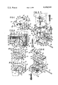
- FIG. 1 is a perspective view of a rotary bending and forming apparatus in accordance with the present invention
- FIG. 2 is a view taken on line 2--2 of the apparatus of FIG. 1;
- FIG. 3 is an exploded view of the apparatus of FIGS. 1 and 2, similarly oriented in a position in which the apparatus will be used in a "down bending" procedure;
- FIGS. 4 and 5 schematically illustrate the apparatus of FIGS. 1-3 in the function thereof.
- FIG. 6 is an exploded view of the apparatus of FIGS. 1 and 2 illustrating such apparatus with an orientation of its parts in the position in which they must assume for an "up bending" operation.
- the embodiment of the invention herein illustrated provides a rotary bending and forming device comprising an operating head and its holder.
- the operating head is a generally cylindrical body 10 modified by having a groove 12 in and coextensive with its outer peripheral surface 14 and opening from its ends 16 and 18.
- the side walls 20 and 22 of the groove 12 form a symmetrical "V", which is uniform in cross section the length of the groove.
- the apex of the "V" is innermost of the body 10 and positions slightly short of and in a plane radial to the central longitudinal axis of the body.
- the apex of the "V" is normally radiused, as is each of the junctions between each of the outermost edges of the side walls 20 and 22 and the respectively adjacent portions of the outer peripheral surface 14 of the body 10.
- the angle defined between the side walls 20 and 22 is slightly less than 90°.
- the configuration of the body 10 and the groove 12 as above described provides the body with two lobes, 24 and 26, the outermost limits of which, with reference to the central longitudinal axis of the body 10, correspond, substantially, to the outermost limits of the side wall surfaces 20 and 22 and lie in and define a common plane.
- the body 10 has a radial socket 30 in the outer surface portion thereof which is diametrically opposite to the apex of the groove 12 and centered between its ends.
- a pin 32 which has one end anchored in the socket 30 projects outward of and radial to the body 10.
- the body of the pin 32 has a circumferential recess 34, located in an adjacent spaced relation to its projected extremity, the purpose of which will be further described.
- the holder for the rocker element comprises a saddle 36 which seats the rocker element and a gib-like retainer 38 which holds the rocker element in a stable, balanced relation to its seat.
- the saddle 36 basically formed of a rectangular block, has a rectangular planar surface 40 serving as its base, front and back surfaces 42 and 44 which are also planar and rectangular in configuration and side surfaces 46 and 48 each of which is planar.
- the surfaces 42, 44, 46 and 48 are equal as to their depth. Adjacent of the side, front and back surfaces are perpendicular to each other, to the base surface 40 and to the plane of the saddle's outermost surface portions 50, the latter of which laterally bound a groove 52 and the seating portion of the saddle.
- the groove 52 provides a generally hemi-cylindrical cavity which is directed inwardly of the surface 50 at a location substantially centered between the front and back surfaces 42 and 44.
- the groove 52 extends between and has its ends at and opening from the side surfaces 46 and 48.
- Formed on and projected from what may be considered the innermost or base portion of the groove 52 are two narrow lands 54 and 56 which extend the length of the groove to have their ends form part of the side surfaces 46 and 48.
- the width of the land 54 extends from about 4:45 to 5:30 and the width of land 56 extends from about 7:15 to 8:00, in a clockwise direction:
- the side wall of the groove 52 is formed to provide thereon a narrow strip-like bearing surface portion 58 which is coextensive with the length of the groove 52.
- the radially innermost surfaces of the projected lands 54 and 56 at the base of the groove 52 and the bearing surface of the strip 58 are formed, in transverse section, on the same radius and, in effect, are designed so as to resemble parallel circumferentially spaced segments of the outer surface of a cylinder having such a radius.
- the radius on which the outer surfaces of lands 54 and 56 as well as the bearing surface of strip 58 are formed is such to complement and nest the cylindrical surface portion 14 of the body 10.
- the lands 54 and 56 are the load accommodating portions of the saddle and serve to seat the body 10 as it is nested in the groove 52 to extend in a direction lengthwise thereof. In the case illustrated, the nesting of the body 10 is to the extent of approximately 180° of its circumference.
- the surface portions of the wall structure bounding the groove 52, other than the portions defined by the lands 54 and 56 and the surface portion 58 are relieved. This provides recessed surface portions between the lands and to either side thereof except for the area of the surface portion 58.
- a recess is formed in the surface of the wall bounding the groove 52, the length thereof, between the land 54 and the surface portion 58, in an immediately adjacent, spaced, parallel relation to the surface portion 58.
- the wall of this recess is arcuate in cross section and has an arcuate extent somewhat greater than 180°. This recess nests approximately three-fourths of the circumference of a lubricant impregnated cord 91 the remainder of which projects outwardly of the wall surface bounding the groove 52 to bear in wiping engagement with the outer peripheral surface 14 of the body 10.
- the surface portion 58 in part defines, with the adjacent edge of a portion 51 of surface 50 with which it merges, one longitudinally extending outer edge at one side of the wall of the groove 52 which lies in the plane of the surface 50.
- the other longitudinally extending outer edge 59 of the wall of the groove 52 is diametrically opposite the edge 58 and also lies in the plane of the surface 50.
- the edge 59 forms one side of a portion 61 of the surface 50 which extends in the direction of the co-planar upper edge of surface portion 44 of the saddle.
- the following edge 63 of the surface portion 61 is in a closely spaced parallel relation to the edge 59 and at the same time parallel to the upper edge of surface portion 44.
- surface portion 61 has a narrow rectangular configuration, its other edges being determined and provided by portions of the upper edges of surfaces 46 and 48. Between the limits defined by the edge 63 and the upper edge of the surface 44 the upper surface of the saddle has a notch 76 directed inwardly thereof, referenced to the plane of the surface 50 which is comprised of its portions 51 and 61. The notch 76 extends between and opens at its ends at and from the surfaces 46 and 48.
- the notch 76 has a uniform right triangular configuration.
- the notch 76 provides the saddle block 36 with an upper surface portion 65 which is inclined downwardly and inwardly from the upper edge of the surface 44 in the direction of the groove 52 and the base surface 40, at an angle with reference to the plane of the surface 50 which is preferably in the range of 10° to 25°.
- the surface portion 65 defines the hypotenuse of the right triangular cross section of the notch 76.
- the base of the right triangular configuration of this cross section is defined by a saddle surface portion 67 which is directed inwardly of and perpendicular to the plane of the surface 50, relatively shallow in depth and includes in the plane thereof the edge 63.
- the gib 38 has a base portion 39 designed to provide for its complementary interfit with and to the surfaces 65 and 67 when fully seated to the saddle.
- Gib 38 is otherwise configured so that in the full seating thereof it presents planar surface portions which are co-planar with the surfaces 46 and 48, a rectangular planar surface portion which is coplanar with the surface 44, a rectangular surface portion 80 which positions outermost from the saddle and defines a plane parallel to and spaced outwardly from the plane of the surface 50 and a surface portion 82 which forms an acute angle with the surface 80 and is obtusely angled with reference to the base portion 39.
- a strip-like portion 84 of its surface portion 82 In the seated condition of the gib a strip-like portion 84 of its surface portion 82, immediately of the surface 80, will overlie a portion of the groove 52 adjacent the edge 59.
- the portion 84 of the gib surface 82 engages in a tangent, bearing, overlapping relation to a side portion of the body 10 in the saddle which extends in a direction lengthwise of its surface 14, in a line which is spaced outwardly from the plane of the surface 50 and parallel thereto as well as inwardly from and parallel to the outermost projected limits of the body 10 as seated in the saddle.
- This bearing engagement of the strip-like surface portion 84 of the gib 38 will be such to hold the body 10 to its load accommodating seat in the saddle. It is to be understood, of course, that the gib will be releasably anchored to the saddle at this point in time, in a manner to be further described.
- the gib surface portion 82 has a longitudinally extended recess 88 therein located in an adjacent, spaced, parallel relation to its surface portion 84, to the side thereof remote from its surface portion 80.
- the wall of the recess 88 is arcuate in cross section and has an arcuate extent greater than 180°.
- the recess 88 by virtue of the nature of its cross section, nests the major extent of the circumference of a lubricant impregnated cord 86, the remainder of which projects outwardly of the wall surface portion 82 to bear in wiping engagement with the outer peripheral surface 14 of the body 10 adjacent the gib surface portion 84, when the gib is anchored to the saddle as above described.
- the inner limit of the slope of the surface portion 82 is interrupted by an offset to accommodate the forming of the gib base portion 39.
- Corner portions of the saddle opposite those including the bore 60 and the bore 62 are respectively provided with a bore 60' and a bore 62', respectively corresponding in detail to that of the bore 60 and the bore 62 and respectively diagonally opposite to the bores to which they correspond.
- the bore 60' and the bore 62' respectively will have applied thereto and therethrough a screw 81 and a dowel 83 to complete the anchoring of the saddle as it is applied to its backing structure.
- a fifth bore is provided in the saddle block 36, between and in a centered and parallel relation to the bores 60' and 62'.
- the bore 64 is counterbored in the end thereof which opens from the surface 40.
- the gib 38 is provided with three bores 85, 87 and 89, which are perpendicular to and open at one end from the surface 80 of the gib and at the opposite end from the gib base portion 39.
- the arrangement of the bores in the gib is such to correspond in spacing with the spacing of the bores 64, 60' and 62'.
- a screw 79 is applied through the base of the saddle block to have its threaded body portion project through the bore 64 and upwardly therefrom as its relatively enlarged head seats in the counterbore in the end thereof which opens at the surface 40.
- the screw 79 is turned, the leading end thereof may be threadedly engaged in the tapped bore 85 of the gib to draw the gib base downwardly into the notch 76 until that point at which the gib is established in a relatively fixed connected relation to the saddle through the medium of its surface portion 84 achieving a bearing engagement thereof to the body 10 which holds this body to its seat in the saddle.
- the precise point at which the position of the gib 38 is fixed with reference to the saddle will be determined by the precise diameter of the particular body 10 which is seated in the saddle.
- the gib is obviously adjustable.
- the gib if necessary, can have that portion of its base which is complementary to the surface 65 relieved to provide for a tighter fit of the gib to the body 10 or, in the alternative, have its surface portion 82 relieved to provide a freer fit of the gib to the body 10 as seated in the saddle.
- a groove 70 is provided in and in a direction transversely of the base of the groove 52, centered between the saddle side surface portions 46 and 48 and parallel thereto.
- the arcuate extent of the groove 70 is limited.
- the groove 70 intersects and extends inwardly of and a fraction of the width of the land 54. From this end the groove 70 extends oppositely to and through the extent of the width of the land 56.
- the pin 32 slip fits into the groove 70, for movement between its side wall surfaces and within the limits defined by the respective ends of the groove.
- a bore 90 is directed inwardly of the saddle surface 42, substantially perpendicular thereto, to have one end open outwardly from the surface 42 and the other end open through one end wall portion of the groove 70 in the vicinity of that side of the land 54 most adjacent the land 56.
- the bore 90 is counterbored at the surface 42 to form an outwardly facing shoulder 92 in a closely adjacent parallel relation to this surface. Bore 90 accommodates a coil spring 94 the innermost end of which is anchored by being coiled around the pin 32, within the recess 34.
- the outermost end 96 of the spring 94 is formed as a loop the position of which is established by drawing the loop 96 outwardly of the shoulder 92 and passing therethrough a pin 98 which bridges and seats to the shoulder 92, when released, under the influence of the bias of the spring 94.
- the operating head defined by the cylindrical body 10 will first be nested in the groove 52 and seated on the bearing surfaces of the lands 54 and 56.
- spring 94 previously connected at one end to the pin 32 will have its other end directed through the bore 90 from its innermost end and its looped end 96 will be pulled outwardly of the bore 90 to have passed therethrough the pin 98, upon release of which the pin 98 will bridge and anchor the outer end of the spring by engagement of the pin to and across the shoulder 92.
- the bias of the spring 94 will be such, as seen in FIGS.
- the gib can be adjusted not only to accommodate wear but essentially to accommodate limited differences in the diameter of the body 10 or wear of the surface 84 cn the gib at any given time.
- the gib 38 is therefore not only releasable and interchangeable but it is adjustable to accomodate normal discrepancies in dimensions of parts.
- the gib 38 can function to establish a balance and stable relation of the body 10 to its seat in the saddle, to accommodate the necessary rotative or rocking movements of this operating head while maintaining the course of the rotating or rocking movement of the operating head repeatedly in an identical pattern, assisted in this connection by the bearing surface portion 58 in connection with the saddle.
- the limit of movement of the gib in the first instance, in the application thereof in the notch 76 of the saddle 36, will be determined by that point at which the gib surface portion 84 comes into a bearing contacting relation with the outer surface of the body 10 to exert a holding function.
- the point of bearing contact will be determined by the original diameter of the outer peripheral surface 14 of the body 10.
- the spring 94 and its return function is not absolutely required, particularly for all applications. However, its use will insure a simple initial coupling of the operating head to the saddle 36 and a quick return of the operating head to its ready position subsequent to the completion of a stroke thereof in the course of which it serves a bending and/or forming function.
- the use of a multi part structure such as herein described facilitates the assembly of the bending and forming apparatus and enables that the same may be accomplished quickly and economically.
- the same result is found in the course of maintenance and replacement of parts of an embodiment such as herein described.
- maintenance procedures will be minimalized because of the nature and character of the construction provided.
- the assembly of the devices of the invention is foolproof and if for any reason the body 10 should fracture, its parts would be held in place for a considerable period of time, thereby minimizing the likelihood of the dropping of the parts of the tool and causing damage to the equipment and material with which it is associated.
- a most important benefit of the mount of the body 10 as described and illustrated is that it provides a very stable, balanced and most effective operation of the body, insurance being given as to the repetition of its performance.
- the body 10 does not skid or mark the material on which it operates in any damaging or disadvantageous manner.
- FIGS. 4 and 5 of the drawings illustrate the application of the invention embodiment to material M backed in part by a forming die A to form in such material a 90° bend
- the details of the bending operation are neither shown nor particularly described since they are well known in the art and are particularly exhibited in the prior art evidenced by U.S. Pat. No. 4,002,049 referred to above in the first instance.
- the exploded view of FIG. 3 provides an illustration of the manner of fixing the saddle to a backing structure, only so much of the backing structure is illustrated as may be necessary for an understanding in this respect.
- FIG. 4 and 5 of the drawings illustrate the application of the invention embodiment to material M backed in part by a forming die A to form in such material a 90° bend
- the details of the bending operation are neither shown nor particularly described since they are well known in the art and are particularly exhibited in the prior art evidenced by U.S. Pat. No. 4,002,049 referred to above in the first instance.
- the exploded view of FIG. 3 provides an illustration
Landscapes
- Engineering & Computer Science (AREA)
- Mechanical Engineering (AREA)
- Earth Drilling (AREA)
Abstract
Description
Claims (9)
Priority Applications (1)
| Application Number | Priority Date | Filing Date | Title |
|---|---|---|---|
| US06/339,133 US4434644A (en) | 1982-01-13 | 1982-01-13 | Rotary bending and forming devices |
Applications Claiming Priority (1)
| Application Number | Priority Date | Filing Date | Title |
|---|---|---|---|
| US06/339,133 US4434644A (en) | 1982-01-13 | 1982-01-13 | Rotary bending and forming devices |
Publications (1)
| Publication Number | Publication Date |
|---|---|
| US4434644A true US4434644A (en) | 1984-03-06 |
Family
ID=23327645
Family Applications (1)
| Application Number | Title | Priority Date | Filing Date |
|---|---|---|---|
| US06/339,133 Expired - Lifetime US4434644A (en) | 1982-01-13 | 1982-01-13 | Rotary bending and forming devices |
Country Status (1)
| Country | Link |
|---|---|
| US (1) | US4434644A (en) |
Cited By (19)
| Publication number | Priority date | Publication date | Assignee | Title |
|---|---|---|---|---|
| US4558582A (en) * | 1982-10-13 | 1985-12-17 | Manfred Meinig | Apparatus for flanging ventilation duct walls |
| US4562721A (en) * | 1983-03-08 | 1986-01-07 | Peter Wukovich Ohg | Machine for folding sheet metal blanks |
| DE9213532U1 (en) * | 1992-10-07 | 1993-01-28 | Haberstock, Rolf, 7897 Küssaberg | Bending device for bending sheet metal parts |
| DE4203680C1 (en) * | 1992-02-08 | 1993-05-06 | Iska Wolfgang Katz Verwaltungs-Gmbh, 7735 Dauchingen, De | |
| US5253502A (en) * | 1991-12-24 | 1993-10-19 | Alco Industries, Inc. | Apparatus and method for bending and forming sheet material |
| US5361620A (en) * | 1993-07-02 | 1994-11-08 | Meadows John L | Method and apparatus for hemming sheets of metal material |
| US5404742A (en) * | 1993-07-09 | 1995-04-11 | Ready Tools Inc. | Rotary hemming device |
| EP0796693A1 (en) * | 1996-03-20 | 1997-09-24 | Heinrich Mummenhoff | Machine for straightening circular saw blades and the like |
| US5820326A (en) * | 1996-03-29 | 1998-10-13 | Product Investment, Inc. | Method and apparatus for making a tamper-evident crown |
| WO1999022887A1 (en) * | 1997-11-04 | 1999-05-14 | Ready Technology, Inc. | Extended length rotary bending and forming devices and methods for manufacture thereof |
| US6065324A (en) * | 1999-07-01 | 2000-05-23 | Power Brake Dies, Inc. | Rotary bender die |
| US6526797B2 (en) * | 2001-03-05 | 2003-03-04 | Umix Co., Ltd. | Negative-angle forming die |
| EP1502671A1 (en) * | 2003-08-01 | 2005-02-02 | Danly IEM , Division of Connell Limited Partnership | Rotary bending tool and method of manufacture |
| US20110030436A1 (en) * | 2009-08-06 | 2011-02-10 | Osamu Makino | Lower die for press bending and tool using the same |
| US8322181B2 (en) | 2010-04-29 | 2012-12-04 | Ready Technology, Inc. | Rotary bending system |
| AT514291A1 (en) * | 2013-07-02 | 2014-11-15 | Trumpf Maschinen Austria Gmbh | bending tool |
| US20170106425A1 (en) * | 2015-10-20 | 2017-04-20 | Dayton Lamina Corporation | Rotary bending devices |
| DE102017006218A1 (en) | 2017-06-28 | 2019-01-03 | Technische Universität Dortmund | Apparatus and method for bending sheet-like workpieces with simultaneous pressure stress superposition |
| CN111496091A (en) * | 2020-04-30 | 2020-08-07 | 海宁市富连机械有限公司 | Portable bending device is used in intelligent mechanical equipment manufacturing |
Citations (9)
| Publication number | Priority date | Publication date | Assignee | Title |
|---|---|---|---|---|
| US105146A (en) | 1870-07-05 | Improvement in self-acting lubricator for axle-boxes | ||
| US2640343A (en) | 1950-10-03 | 1953-06-02 | Stout Frederick Sturgis | Skin burning treatment |
| US2963066A (en) | 1955-09-14 | 1960-12-06 | Artcraft Venetian Blind Mfg Co | Apparatus for cutting and bending strip material |
| US3301034A (en) | 1964-02-11 | 1967-01-31 | Bastian Blessing Co | Sheet metal die forming apparatus |
| US3400568A (en) | 1965-10-22 | 1968-09-10 | John F Cech | Die for making right angles on steel |
| SU381437A1 (en) | 1969-03-25 | 1973-05-22 | DEVICE FOR FEEDING LUBRICATION TO THE ROLLED STRIP DEFORMATION AREA | |
| US4002049A (en) | 1975-06-09 | 1977-01-11 | Ready Stamping System, Inc. | Forming tool for use in a die assembly |
| SU618146A1 (en) | 1977-02-07 | 1978-06-21 | Краматорский Научно-Исследовательский И Проектно-Технологический Институт Машиностроения | Roll stand working roll bearing |
| US4181002A (en) | 1976-09-22 | 1980-01-01 | Walter Eckold Vorrichtungs u. Geratebau Sperrluttertal | Tools for bending sheet metal |
-
1982
- 1982-01-13 US US06/339,133 patent/US4434644A/en not_active Expired - Lifetime
Patent Citations (9)
| Publication number | Priority date | Publication date | Assignee | Title |
|---|---|---|---|---|
| US105146A (en) | 1870-07-05 | Improvement in self-acting lubricator for axle-boxes | ||
| US2640343A (en) | 1950-10-03 | 1953-06-02 | Stout Frederick Sturgis | Skin burning treatment |
| US2963066A (en) | 1955-09-14 | 1960-12-06 | Artcraft Venetian Blind Mfg Co | Apparatus for cutting and bending strip material |
| US3301034A (en) | 1964-02-11 | 1967-01-31 | Bastian Blessing Co | Sheet metal die forming apparatus |
| US3400568A (en) | 1965-10-22 | 1968-09-10 | John F Cech | Die for making right angles on steel |
| SU381437A1 (en) | 1969-03-25 | 1973-05-22 | DEVICE FOR FEEDING LUBRICATION TO THE ROLLED STRIP DEFORMATION AREA | |
| US4002049A (en) | 1975-06-09 | 1977-01-11 | Ready Stamping System, Inc. | Forming tool for use in a die assembly |
| US4181002A (en) | 1976-09-22 | 1980-01-01 | Walter Eckold Vorrichtungs u. Geratebau Sperrluttertal | Tools for bending sheet metal |
| SU618146A1 (en) | 1977-02-07 | 1978-06-21 | Краматорский Научно-Исследовательский И Проектно-Технологический Институт Машиностроения | Roll stand working roll bearing |
Cited By (25)
| Publication number | Priority date | Publication date | Assignee | Title |
|---|---|---|---|---|
| US4558582A (en) * | 1982-10-13 | 1985-12-17 | Manfred Meinig | Apparatus for flanging ventilation duct walls |
| US4562721A (en) * | 1983-03-08 | 1986-01-07 | Peter Wukovich Ohg | Machine for folding sheet metal blanks |
| US5253502A (en) * | 1991-12-24 | 1993-10-19 | Alco Industries, Inc. | Apparatus and method for bending and forming sheet material |
| DE4203680C1 (en) * | 1992-02-08 | 1993-05-06 | Iska Wolfgang Katz Verwaltungs-Gmbh, 7735 Dauchingen, De | |
| US5341669A (en) * | 1992-02-08 | 1994-08-30 | Ready Tools, Inc. | Rotary bending tool with continuous lubrication |
| DE9213532U1 (en) * | 1992-10-07 | 1993-01-28 | Haberstock, Rolf, 7897 Küssaberg | Bending device for bending sheet metal parts |
| US5361620A (en) * | 1993-07-02 | 1994-11-08 | Meadows John L | Method and apparatus for hemming sheets of metal material |
| US5404742A (en) * | 1993-07-09 | 1995-04-11 | Ready Tools Inc. | Rotary hemming device |
| EP0796693A1 (en) * | 1996-03-20 | 1997-09-24 | Heinrich Mummenhoff | Machine for straightening circular saw blades and the like |
| US5820326A (en) * | 1996-03-29 | 1998-10-13 | Product Investment, Inc. | Method and apparatus for making a tamper-evident crown |
| WO1999022887A1 (en) * | 1997-11-04 | 1999-05-14 | Ready Technology, Inc. | Extended length rotary bending and forming devices and methods for manufacture thereof |
| US5913931A (en) * | 1997-11-04 | 1999-06-22 | Ready Technology, Inc. | Extended length rotary bending and forming devices and methods for manufacture thereof |
| US6065324A (en) * | 1999-07-01 | 2000-05-23 | Power Brake Dies, Inc. | Rotary bender die |
| US6526797B2 (en) * | 2001-03-05 | 2003-03-04 | Umix Co., Ltd. | Negative-angle forming die |
| EP1502671A1 (en) * | 2003-08-01 | 2005-02-02 | Danly IEM , Division of Connell Limited Partnership | Rotary bending tool and method of manufacture |
| US6983634B2 (en) * | 2003-08-01 | 2006-01-10 | Danly Iem | Rotary bending tool and method of manufacture |
| US20110030436A1 (en) * | 2009-08-06 | 2011-02-10 | Osamu Makino | Lower die for press bending and tool using the same |
| US8695394B2 (en) * | 2009-08-06 | 2014-04-15 | Osamu Makino | Lower die for press bending and tool using the same |
| US8322181B2 (en) | 2010-04-29 | 2012-12-04 | Ready Technology, Inc. | Rotary bending system |
| AT514291A1 (en) * | 2013-07-02 | 2014-11-15 | Trumpf Maschinen Austria Gmbh | bending tool |
| US20170106425A1 (en) * | 2015-10-20 | 2017-04-20 | Dayton Lamina Corporation | Rotary bending devices |
| US9744579B2 (en) * | 2015-10-20 | 2017-08-29 | Dayton Lamina Corporation | Rotary bending devices |
| DE102017006218A1 (en) | 2017-06-28 | 2019-01-03 | Technische Universität Dortmund | Apparatus and method for bending sheet-like workpieces with simultaneous pressure stress superposition |
| EP3424606A1 (en) | 2017-06-28 | 2019-01-09 | Technische Universität Dortmund | Device and method of bending metal sheet during simultaneous pressure tension superimposition |
| CN111496091A (en) * | 2020-04-30 | 2020-08-07 | 海宁市富连机械有限公司 | Portable bending device is used in intelligent mechanical equipment manufacturing |
Similar Documents
| Publication | Publication Date | Title |
|---|---|---|
| US4434644A (en) | Rotary bending and forming devices | |
| US6560879B2 (en) | Chain saw adjuster | |
| KR100314926B1 (en) | Cutting tools | |
| US3122048A (en) | Adjustable backing key | |
| US3871777A (en) | Clamping means for split rotary anvil and the like | |
| EP0666144B1 (en) | Device for blocking a piece on a support plane like a table for operating machines | |
| US2705983A (en) | Displaceable half nuts for quick release clamps | |
| US4376414A (en) | Printing plate attachment arrangement | |
| JPS6288502A (en) | Clamping pin for cutting tool holder | |
| JPH0435282B2 (en) | ||
| JP2806936B2 (en) | Mechanical booster | |
| US4019726A (en) | Cam lock jaws for machinist vise | |
| US4375284A (en) | Fly tiers' vise | |
| US4400116A (en) | Cutting tool with adjustable chip breaker | |
| CA1095399A (en) | Die holder assembly | |
| US3633258A (en) | Insert tool holder and cutting tool therefor | |
| JPS6114727Y2 (en) | ||
| US2953950A (en) | Boring bar | |
| US4029301A (en) | Connective means for providing variable attitude | |
| US5794321A (en) | Spring compression tool and method | |
| JPS6230619Y2 (en) | ||
| US1797337A (en) | Connecting pin | |
| JP4465562B2 (en) | Round blade tool | |
| KR900010254A (en) | Support structure of shaft | |
| EP0745191B1 (en) | Sliding clamp |
Legal Events
| Date | Code | Title | Description |
|---|---|---|---|
| AS | Assignment |
Owner name: READY TOOLS, INC., DAYTON, OH. AN OH CORP. Free format text: ASSIGNMENT OF ASSIGNORS INTEREST.;ASSIGNORS:GARGRAVE, ROBERT J.;THOMPSON, JOHN K.;COMSTOCK, JAMES F.;REEL/FRAME:004199/0493 Effective date: 19831206 Owner name: READY TOOLS, INC., DAYTON, OH. AN CORP., OHIO Free format text: ASSIGNMENT OF ASSIGNORS INTEREST;ASSIGNORS:GARGRAVE, ROBERT J.;THOMPSON, JOHN K.;COMSTOCK, JAMES F.;REEL/FRAME:004199/0493 Effective date: 19831206 |
|
| STCF | Information on status: patent grant |
Free format text: PATENTED CASE |
|
| CC | Certificate of correction | ||
| MAFP | Maintenance fee payment |
Free format text: PAYMENT OF MAINTENANCE FEE, 4TH YEAR, PL 96-517 (ORIGINAL EVENT CODE: M170); ENTITY STATUS OF PATENT OWNER: SMALL ENTITY Year of fee payment: 4 |
|
| FEPP | Fee payment procedure |
Free format text: PAYOR NUMBER ASSIGNED (ORIGINAL EVENT CODE: ASPN); ENTITY STATUS OF PATENT OWNER: SMALL ENTITY |
|
| MAFP | Maintenance fee payment |
Free format text: PAYMENT OF MAINTENANCE FEE, 8TH YEAR, PL 96-517 (ORIGINAL EVENT CODE: M171); ENTITY STATUS OF PATENT OWNER: SMALL ENTITY Year of fee payment: 8 |
|
| AS | Assignment |
Owner name: READY TECH, INC., OHIO Free format text: ASSIGNMENT OF ASSIGNORS INTEREST;ASSIGNOR:READY TOOLS, INC.;REEL/FRAME:007244/0465 Effective date: 19941028 Owner name: READY TOOLS INC., OHIO Free format text: SECURITY INTEREST;ASSIGNOR:READY TECH, INC.;REEL/FRAME:007244/0454 Effective date: 19941028 |
|
| MAFP | Maintenance fee payment |
Free format text: PAYMENT OF MAINTENANCE FEE, 12TH YR, SMALL ENTITY (ORIGINAL EVENT CODE: M285); ENTITY STATUS OF PATENT OWNER: SMALL ENTITY Year of fee payment: 12 |