US4430077A - Injection site with tamper indicator - Google Patents
Injection site with tamper indicator Download PDFInfo
- Publication number
- US4430077A US4430077A US06/392,413 US39241382A US4430077A US 4430077 A US4430077 A US 4430077A US 39241382 A US39241382 A US 39241382A US 4430077 A US4430077 A US 4430077A
- Authority
- US
- United States
- Prior art keywords
- inlet
- injection site
- tamper indicating
- frangible section
- pierceable
- Prior art date
- Legal status (The legal status is an assumption and is not a legal conclusion. Google has not performed a legal analysis and makes no representation as to the accuracy of the status listed.)
- Expired - Lifetime
Links
Images

Classifications
-
- A—HUMAN NECESSITIES
- A61—MEDICAL OR VETERINARY SCIENCE; HYGIENE
- A61M—DEVICES FOR INTRODUCING MEDIA INTO, OR ONTO, THE BODY; DEVICES FOR TRANSDUCING BODY MEDIA OR FOR TAKING MEDIA FROM THE BODY; DEVICES FOR PRODUCING OR ENDING SLEEP OR STUPOR
- A61M39/00—Tubes, tube connectors, tube couplings, valves, access sites or the like, specially adapted for medical use
- A61M39/02—Access sites
- A61M39/04—Access sites having pierceable self-sealing members
Definitions
- the present invention concerns an injection site which carries a device for indicating that an injection has occurred or that the injection site has been tampered with.
- Injection sites are commonly used in hospitals where a parenteral fluid is being fed to a patient intravenously and it is also desired to combine another medicament with the parenteral fluid.
- the parenteral fluid is fed via flexible conduit to one inlet of a connecting device, commonly called an injection site.
- Flexible conduit extends from the outlet of the injection site to an appropriate device for administering the liquid to the patient.
- the injection site typically has a second inlet, having a pierceable diaphragm connected thereto.
- the supplementary medicament is injected into the second inlet by a hypodermic syringe and it becomes combined with the parenteral liquid for administration to the patient.
- a type of injection site which comprises the above-described characteristics is disclosed in Herbert Mittleman U.S. Pat. No. 4,00,740, issued Jan. 4, 1977, and entitled "Injection Site".
- the pierceable diaphragm is formed of a self-sealable material, such as Latex or silicone rubber, and it is often impossible to determine whether an injection has been made into the diaphragm by merely viewing it.
- a self-sealable material such as Latex or silicone rubber
- prior art injection sites generally utilize pierceable diaphragms which are exposed to ambient surroundings, it is possible for the pierceable diaphragm to have come in contact with various fluid contaminants without anyone knowing whether such has occurred. Further, if the injection site is not stored properly, a layer of dust may collect upon the pierceable diaphragm.
- Another object of the present invention is to provide tamper indicating means for an injection site, which also serves to prevent the pierceable diaphragm of the injection site from being contaminated with dust or certain gross contaminants.
- Another object of the present invention is to provide an injection site including tamper indicating means that is simple in construction and efficient to manufacture.
- a still further object of the present invention is to provide tamper indicating means for an injection site, which renders the pierceable diaphragm inaccessible until a portion of the tamper indicating means is removed.
- a tamper indicating device for connection to an injection site having a main body portion, a first inlet, a second inlet including a pierceable, self-sealing member, an outlet, and with the first inlet, second inlet and outlet being in fluid communication with the main body portion.
- the tamper indicating device comprises a cap covering the second inlet and rendering the pierceable, self-sealing member inaccessible.
- the cap comprises a first portion for connection to the second inlet and a second portion separated from the first portion by a frangible section.
- a handle extends from the second portion and is operable when actuated to break the second portion away from the first portion at the frangible section. In this manner, the pierceable, self-sealing member becomes accessible while the first portion remains connected to the second inlet.
- the first portion comprises a ring member substantially encircling the second inlet.
- the second portion comprises a cup-shaped member and the frangible section comprises an annular thin section coupling the first portion to the second portion.
- the tamper indicating means has a color that is different from the color of the second inlet so that when the second portion is broken away from the first portion, the color of the first portion which remains connected to the second inlet will contrast with the color of the second inlet, to show that the injection site had a tamper indicating device that has been partially removed.
- FIG. 1 is a perspective view of an injection site with tamper indicating means, constructed in accordance with the principles of the present invention.
- FIG. 2 is a top plan view of a tamper indicating device constructed in accordance with the principles of the present invention.
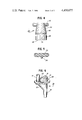
- FIG. 3 is a cross-sectional elevation thereof, taken along the plane of the line 3--3 of FIG. 2.
- FIG. 4 is a left side elevation of the tamper indicating device of FIG. 2.
- FIG. 5 is a cross-sectional elevation taken along the plane of the line 5--5 of FIG. 2.
- FIG. 6 is a perspective view of the injection site of FIG. 1, after a portion of the tamper indicating means has been removed.
- the injection site 10 illustrated therein comprises a first inlet 12 for connection to a tube leading to a parenteral source of liquid, a second inlet 14 (FIG. 6) having a pierceable self-sealing diaphragm located therein as is well-known in the art, an outlet 18 for coupling to tubing which is connected to a patient, a main body portion 20 with which inlets 12 and 14 and outlet 18 communicate, and a ridge 22 connecting inlets 12 and 14 to aid in preventing tubing from becoming caught between these inlets.
- Such an injection site is illustrated in a pending U.S. patent application in the name of Herbert Mittleman, Ser. No. 892,766, filed Apr. 3, 1978. Referring to FIG. 6, it can be seen that the top plane of pierceable diaphragm 16 is generally coplanar with the top of second inlet 14.
- Tamper indicating device 24 is formed in a one-piece integral molded construction, and comprises a first portion 26, which is cylindrical with its internal wall being solvent bonded to the external wall of second inlet 14, a second portion 28 which is generally cup-shaped and is separated from first portion 26 by a frangible section 30, and a handle 32 which is a generally flat member extending perpendicular to the axis of cup-shaped second portion 28 (and thus perpendicular to the axis of second inlet 14).
- Frangible section 30 comprises an annular thin section, as most clearly illustrated in FIG. 3, with frangible section 30 being in general alignment with the top of second inlet 14.
- frangible section 30 being in general alignment with the top of second inlet 14.
- a gusset 34 bridging the underside of handle 32 and a side of second portion 28 is provided.
- tamper indicating device 24 defines a rectangular slot 36 (FIG. 4) which extends from the bottom 38 of first portion 26 to a level just above the frangible section 30.
- This slot 36 is of a width to accommodate ridge 22, whereby the first portion 26 will encircle second inlet 14 except for ridge 22.
- Slot 36 is such that its top wall 40 is above the plane of the top of inlet 14, thereby providing a small opening so that inlet 14 can be ethylene trioxide sterilized notwithstanding the presence of tamper indicating device 24 thereon.
- FIGS. 1 and 6 it can be seen that when tamper indicating device 24 is on second inlet 14, pierceable diaphragm 16 is inaccessible. In order for pierceable diaphragm 16 to become accessible, handle 32 is lifted upwardly to break the frangible section 30 so that second portion 28 can be removed from first portion 26. When second portion 28 is removed, the first portion 26 will remain attached to second inlet 14 as illustrated in FIG. 6.
- the tamper indicating device 24 is formed of a plastic having a different color than the color of second inlet 14, so that once handle 32 and second portion 28 are removed, an operator can readily see that a portion of the tamper indicating device 24 has been removed.
- the tamper indicating device 24 may be a bright color, such as red, while second inlet 14 may be white.
Abstract
Description
Claims (3)
Priority Applications (1)
| Application Number | Priority Date | Filing Date | Title |
|---|---|---|---|
| US06/392,413 US4430077A (en) | 1980-10-10 | 1982-06-25 | Injection site with tamper indicator |
Applications Claiming Priority (2)
| Application Number | Priority Date | Filing Date | Title |
|---|---|---|---|
| US19588580A | 1980-10-10 | 1980-10-10 | |
| US06/392,413 US4430077A (en) | 1980-10-10 | 1982-06-25 | Injection site with tamper indicator |
Related Parent Applications (1)
| Application Number | Title | Priority Date | Filing Date |
|---|---|---|---|
| US19588580A Continuation | 1980-10-10 | 1980-10-10 |
Publications (1)
| Publication Number | Publication Date |
|---|---|
| US4430077A true US4430077A (en) | 1984-02-07 |
Family
ID=26891439
Family Applications (1)
| Application Number | Title | Priority Date | Filing Date |
|---|---|---|---|
| US06/392,413 Expired - Lifetime US4430077A (en) | 1980-10-10 | 1982-06-25 | Injection site with tamper indicator |
Country Status (1)
| Country | Link |
|---|---|
| US (1) | US4430077A (en) |
Cited By (54)
| Publication number | Priority date | Publication date | Assignee | Title |
|---|---|---|---|---|
| US4624667A (en) * | 1984-06-11 | 1986-11-25 | Abbott Laboratories | Additive transfer device |
| US4632673A (en) * | 1983-06-15 | 1986-12-30 | Hantaaki Oy | Pierceable port for containers |
| US4632267A (en) * | 1984-11-13 | 1986-12-30 | Baxter Travenol Laboratories, Inc. | Overmolded port closure |
| US4731061A (en) * | 1985-08-08 | 1988-03-15 | Pall Corporation | Apparatus and method for reducing risk of contamination and delivering to a patient pharmaceutically-acceptable material |
| US4903855A (en) * | 1988-11-25 | 1990-02-27 | Baxter International Inc. | Closure and port assembly |
| US4966582A (en) * | 1989-06-30 | 1990-10-30 | Sit James K | Injection site platform |
| US5088995A (en) * | 1990-06-22 | 1992-02-18 | Baxter International Inc. | Port and closure assembly including a resealing injection site for a container |
| US5222950A (en) * | 1990-07-16 | 1993-06-29 | Eisenberg Melvin I | Quick release tamper evident closure device |
| US5833089A (en) * | 1991-10-04 | 1998-11-10 | Manni; Charles | Packaging for the extemporaneous preparation of drug products |
| US20030114795A1 (en) * | 2001-12-17 | 2003-06-19 | Faries, Durward I. | Method and apparatus for heating solutions within intravenous lines to desired temperatures during infusion |
| US20070106243A1 (en) * | 2005-10-27 | 2007-05-10 | Faries Durward I Jr | Method and apparatus to indicate prior use of a medical item |
| US20080205481A1 (en) * | 2007-02-22 | 2008-08-28 | Faries Durward I | Method and Apparatus for Measurement and Control of Temperature for Infused Liquids |
| US20100168671A1 (en) * | 1997-03-03 | 2010-07-01 | Faries Jr Durward I | Method and Apparatus for Pressure Infusion and Temperature Control of Infused Liquids |
| US20110046550A1 (en) * | 2009-08-21 | 2011-02-24 | Becton Dickinson France S.A.S. | Tamper Evident Tip Cap and Syringe |
| US8487738B2 (en) | 2006-03-20 | 2013-07-16 | Medical Solutions, Inc. | Method and apparatus for securely storing medical items within a thermal treatment system |
| US8821011B2 (en) | 1999-03-30 | 2014-09-02 | Medical Solutions, Inc. | Method and apparatus for monitoring temperature of intravenously delivered fluids and other medical items |
| US8845586B2 (en) | 2004-03-09 | 2014-09-30 | Patented Medical Solutions Llc | Method and apparatus for facilitating injection of medication into an intravenous fluid line while maintaining sterility of infused fluids |
| US9119912B2 (en) | 2001-03-12 | 2015-09-01 | Medical Solutions, Inc. | Method and apparatus for controlling pressurized infusion and temperature of infused liquids |
| US9211381B2 (en) | 2012-01-20 | 2015-12-15 | Medical Solutions, Inc. | Method and apparatus for controlling temperature of medical liquids |
| US9656029B2 (en) | 2013-02-15 | 2017-05-23 | Medical Solutions, Inc. | Plural medical item warming system and method for warming a plurality of medical items to desired temperatures |
| US9821152B1 (en) | 2013-03-04 | 2017-11-21 | Medical Device Engineering, LLC. | Closure assembly |
| US9855191B1 (en) | 2013-12-09 | 2018-01-02 | Jonathan J. Vitello | Tamper evident shield assembly with tracking |
| US10166347B1 (en) | 2014-07-18 | 2019-01-01 | Patrick Vitello | Closure assembly for a medical device |
| US10166343B1 (en) | 2015-03-13 | 2019-01-01 | Timothy Brandon Hunt | Noise evident tamper cap |
| US10183129B1 (en) | 2010-12-03 | 2019-01-22 | Medical Device Engineering, Llc | Tamper indicating closure assembly |
| US10207099B1 (en) | 2014-02-21 | 2019-02-19 | Patrick Vitello | Closure assembly for medical fitting |
| US10300263B1 (en) | 2015-02-27 | 2019-05-28 | Timothy Brandon Hunt | Closure assembly for a medical connector |
| US10307548B1 (en) | 2016-12-14 | 2019-06-04 | Timothy Brandon Hunt | Tracking system and method for medical devices |
| US10315024B1 (en) | 2015-03-19 | 2019-06-11 | Patick Vitello | Torque limiting closure assembly |
| US10758684B1 (en) | 2017-03-03 | 2020-09-01 | Jonathan J. Vitello | Tamper evident assembly |
| USD903865S1 (en) | 2018-11-19 | 2020-12-01 | International Medical Industries, Inc. | Self-righting tip cap |
| US10888672B1 (en) | 2017-04-06 | 2021-01-12 | International Medical Industries, Inc. | Tamper evident closure assembly for a medical device |
| US10898659B1 (en) | 2017-05-19 | 2021-01-26 | International Medical Industries Inc. | System for handling and dispensing a plurality of products |
| US10912898B1 (en) | 2014-02-03 | 2021-02-09 | Medical Device Engineering Llc | Tamper evident cap for medical fitting |
| US10933202B1 (en) | 2017-05-19 | 2021-03-02 | International Medical Industries Inc. | Indicator member of low strength resistance for a tamper evident closure |
| US10953162B1 (en) | 2016-12-28 | 2021-03-23 | Timothy Brandon Hunt | Tamper evident closure assembly |
| US11040149B1 (en) | 2017-03-30 | 2021-06-22 | International Medical Industries | Tamper evident closure assembly for a medical device |
| US11097071B1 (en) | 2016-12-14 | 2021-08-24 | International Medical Industries Inc. | Tamper evident assembly |
| US11278681B1 (en) | 2018-02-20 | 2022-03-22 | Robert Banik | Tamper evident adaptor closure |
| USD948713S1 (en) | 2019-09-03 | 2022-04-12 | International Medical Industries, Inc. | Asymmetrical self righting tip cap |
| US11357588B1 (en) | 2019-11-25 | 2022-06-14 | Patrick Vitello | Needle packaging and disposal assembly |
| US11413406B1 (en) | 2018-03-05 | 2022-08-16 | Jonathan J. Vitello | Tamper evident assembly |
| US11426328B1 (en) | 2018-08-31 | 2022-08-30 | Alexander Ollmann | Closure for a medical container |
| US11471610B1 (en) | 2018-10-18 | 2022-10-18 | Robert Banik | Asymmetrical closure for a medical device |
| US11523970B1 (en) | 2020-08-28 | 2022-12-13 | Jonathan Vitello | Tamper evident shield |
| US11541180B1 (en) | 2017-12-21 | 2023-01-03 | Patrick Vitello | Closure assembly having a snap-fit construction |
| US11690994B1 (en) | 2018-07-13 | 2023-07-04 | Robert Banik | Modular medical connector |
| US11697527B1 (en) | 2019-09-11 | 2023-07-11 | Logan Hendren | Tamper evident closure assembly |
| US11779520B1 (en) | 2018-07-02 | 2023-10-10 | Patrick Vitello | Closure for a medical dispenser including a one-piece tip cap |
| US11793987B1 (en) | 2018-07-02 | 2023-10-24 | Patrick Vitello | Flex tec closure assembly for a medical dispenser |
| US11857751B1 (en) | 2018-07-02 | 2024-01-02 | International Medical Industries Inc. | Assembly for a medical connector |
| US11872187B1 (en) | 2020-12-28 | 2024-01-16 | Jonathan Vitello | Tamper evident seal for a vial cover |
| US11904149B1 (en) | 2020-02-18 | 2024-02-20 | Jonathan Vitello | Oral tamper evident closure with retained indicator |
| US11911339B1 (en) | 2019-08-15 | 2024-02-27 | Peter Lehel | Universal additive port cap |
-
1982
- 1982-06-25 US US06/392,413 patent/US4430077A/en not_active Expired - Lifetime
Cited By (70)
| Publication number | Priority date | Publication date | Assignee | Title |
|---|---|---|---|---|
| US4632673A (en) * | 1983-06-15 | 1986-12-30 | Hantaaki Oy | Pierceable port for containers |
| US4624667A (en) * | 1984-06-11 | 1986-11-25 | Abbott Laboratories | Additive transfer device |
| US4632267A (en) * | 1984-11-13 | 1986-12-30 | Baxter Travenol Laboratories, Inc. | Overmolded port closure |
| US4731061A (en) * | 1985-08-08 | 1988-03-15 | Pall Corporation | Apparatus and method for reducing risk of contamination and delivering to a patient pharmaceutically-acceptable material |
| US4903855A (en) * | 1988-11-25 | 1990-02-27 | Baxter International Inc. | Closure and port assembly |
| WO1990006143A1 (en) * | 1988-11-25 | 1990-06-14 | Baxter International Inc. | Closure and port assembly |
| US4966582A (en) * | 1989-06-30 | 1990-10-30 | Sit James K | Injection site platform |
| US5088995A (en) * | 1990-06-22 | 1992-02-18 | Baxter International Inc. | Port and closure assembly including a resealing injection site for a container |
| US5222950A (en) * | 1990-07-16 | 1993-06-29 | Eisenberg Melvin I | Quick release tamper evident closure device |
| US5833089A (en) * | 1991-10-04 | 1998-11-10 | Manni; Charles | Packaging for the extemporaneous preparation of drug products |
| US20100168671A1 (en) * | 1997-03-03 | 2010-07-01 | Faries Jr Durward I | Method and Apparatus for Pressure Infusion and Temperature Control of Infused Liquids |
| US8313462B2 (en) | 1997-03-03 | 2012-11-20 | Medical Solutions, Inc. | Method and apparatus for pressure infusion and temperature control of infused liquids |
| US8920387B2 (en) | 1997-03-03 | 2014-12-30 | Medical Solutions, Inc. | Method and apparatus for pressure infusion and temperature control of infused liquids |
| US8821011B2 (en) | 1999-03-30 | 2014-09-02 | Medical Solutions, Inc. | Method and apparatus for monitoring temperature of intravenously delivered fluids and other medical items |
| US9119912B2 (en) | 2001-03-12 | 2015-09-01 | Medical Solutions, Inc. | Method and apparatus for controlling pressurized infusion and temperature of infused liquids |
| US20050142013A1 (en) * | 2001-12-17 | 2005-06-30 | Faries Durward I.Jr. | Method and apparatus for heating solutions within intravenous lines to desired temperatures during infusion |
| US20030114795A1 (en) * | 2001-12-17 | 2003-06-19 | Faries, Durward I. | Method and apparatus for heating solutions within intravenous lines to desired temperatures during infusion |
| US9492624B2 (en) | 2001-12-17 | 2016-11-15 | Medical Solutions, Inc. | Method and apparatus for heating solutions within intravenous lines to desired temperatures during infusion |
| US8920372B2 (en) | 2001-12-17 | 2014-12-30 | Medical Solutions, Inc. | Method and apparatus for heating solutions within intravenous lines to desired temperatures during infusion |
| US8226605B2 (en) | 2001-12-17 | 2012-07-24 | Medical Solutions, Inc. | Method and apparatus for heating solutions within intravenous lines to desired temperatures during infusion |
| US8845586B2 (en) | 2004-03-09 | 2014-09-30 | Patented Medical Solutions Llc | Method and apparatus for facilitating injection of medication into an intravenous fluid line while maintaining sterility of infused fluids |
| US20100222762A1 (en) * | 2005-10-27 | 2010-09-02 | Faries Jr Durward I | Method and Apparatus to Indicate Prior Use of a Medical Item |
| US8444599B2 (en) * | 2005-10-27 | 2013-05-21 | Patented Medical Solutions, Llc | Method and apparatus to indicate prior use of a medical item |
| US8636691B2 (en) * | 2005-10-27 | 2014-01-28 | Patented Medical Solutions, Llc | Method and apparatus to indicate prior use of a medical item |
| US20070106243A1 (en) * | 2005-10-27 | 2007-05-10 | Faries Durward I Jr | Method and apparatus to indicate prior use of a medical item |
| US20100222763A1 (en) * | 2005-10-27 | 2010-09-02 | Faries Jr Durward I | Method and Apparatus to Indicate Prior Use of a Medical Item |
| US7740611B2 (en) * | 2005-10-27 | 2010-06-22 | Patented Medical Solutions, Llc | Method and apparatus to indicate prior use of a medical item |
| US8487738B2 (en) | 2006-03-20 | 2013-07-16 | Medical Solutions, Inc. | Method and apparatus for securely storing medical items within a thermal treatment system |
| US8226293B2 (en) | 2007-02-22 | 2012-07-24 | Medical Solutions, Inc. | Method and apparatus for measurement and control of temperature for infused liquids |
| US20080205481A1 (en) * | 2007-02-22 | 2008-08-28 | Faries Durward I | Method and Apparatus for Measurement and Control of Temperature for Infused Liquids |
| US9480801B2 (en) | 2009-08-21 | 2016-11-01 | Becton Dickinson France | Tamper evident tip cap and syringe |
| US20110046550A1 (en) * | 2009-08-21 | 2011-02-24 | Becton Dickinson France S.A.S. | Tamper Evident Tip Cap and Syringe |
| US10183129B1 (en) | 2010-12-03 | 2019-01-22 | Medical Device Engineering, Llc | Tamper indicating closure assembly |
| US9211381B2 (en) | 2012-01-20 | 2015-12-15 | Medical Solutions, Inc. | Method and apparatus for controlling temperature of medical liquids |
| US9764100B2 (en) | 2012-01-20 | 2017-09-19 | Medical Solutions, Inc. | Method and apparatus for controlling temperature of medical liquids |
| US9656029B2 (en) | 2013-02-15 | 2017-05-23 | Medical Solutions, Inc. | Plural medical item warming system and method for warming a plurality of medical items to desired temperatures |
| US9821152B1 (en) | 2013-03-04 | 2017-11-21 | Medical Device Engineering, LLC. | Closure assembly |
| US9855191B1 (en) | 2013-12-09 | 2018-01-02 | Jonathan J. Vitello | Tamper evident shield assembly with tracking |
| US10912898B1 (en) | 2014-02-03 | 2021-02-09 | Medical Device Engineering Llc | Tamper evident cap for medical fitting |
| US11040154B1 (en) | 2014-02-03 | 2021-06-22 | Medical Device Engineering Llc | Tamper evident cap for medical fitting |
| US10207099B1 (en) | 2014-02-21 | 2019-02-19 | Patrick Vitello | Closure assembly for medical fitting |
| US10166347B1 (en) | 2014-07-18 | 2019-01-01 | Patrick Vitello | Closure assembly for a medical device |
| US10300263B1 (en) | 2015-02-27 | 2019-05-28 | Timothy Brandon Hunt | Closure assembly for a medical connector |
| US10166343B1 (en) | 2015-03-13 | 2019-01-01 | Timothy Brandon Hunt | Noise evident tamper cap |
| US10315024B1 (en) | 2015-03-19 | 2019-06-11 | Patick Vitello | Torque limiting closure assembly |
| US10307548B1 (en) | 2016-12-14 | 2019-06-04 | Timothy Brandon Hunt | Tracking system and method for medical devices |
| US11097071B1 (en) | 2016-12-14 | 2021-08-24 | International Medical Industries Inc. | Tamper evident assembly |
| US10953162B1 (en) | 2016-12-28 | 2021-03-23 | Timothy Brandon Hunt | Tamper evident closure assembly |
| US10758684B1 (en) | 2017-03-03 | 2020-09-01 | Jonathan J. Vitello | Tamper evident assembly |
| US11040149B1 (en) | 2017-03-30 | 2021-06-22 | International Medical Industries | Tamper evident closure assembly for a medical device |
| US10888672B1 (en) | 2017-04-06 | 2021-01-12 | International Medical Industries, Inc. | Tamper evident closure assembly for a medical device |
| US10898659B1 (en) | 2017-05-19 | 2021-01-26 | International Medical Industries Inc. | System for handling and dispensing a plurality of products |
| US10933202B1 (en) | 2017-05-19 | 2021-03-02 | International Medical Industries Inc. | Indicator member of low strength resistance for a tamper evident closure |
| US11541180B1 (en) | 2017-12-21 | 2023-01-03 | Patrick Vitello | Closure assembly having a snap-fit construction |
| US11278681B1 (en) | 2018-02-20 | 2022-03-22 | Robert Banik | Tamper evident adaptor closure |
| US11413406B1 (en) | 2018-03-05 | 2022-08-16 | Jonathan J. Vitello | Tamper evident assembly |
| US11779520B1 (en) | 2018-07-02 | 2023-10-10 | Patrick Vitello | Closure for a medical dispenser including a one-piece tip cap |
| US11793987B1 (en) | 2018-07-02 | 2023-10-24 | Patrick Vitello | Flex tec closure assembly for a medical dispenser |
| US11857751B1 (en) | 2018-07-02 | 2024-01-02 | International Medical Industries Inc. | Assembly for a medical connector |
| US11690994B1 (en) | 2018-07-13 | 2023-07-04 | Robert Banik | Modular medical connector |
| US11426328B1 (en) | 2018-08-31 | 2022-08-30 | Alexander Ollmann | Closure for a medical container |
| US11471610B1 (en) | 2018-10-18 | 2022-10-18 | Robert Banik | Asymmetrical closure for a medical device |
| USD903865S1 (en) | 2018-11-19 | 2020-12-01 | International Medical Industries, Inc. | Self-righting tip cap |
| US11911339B1 (en) | 2019-08-15 | 2024-02-27 | Peter Lehel | Universal additive port cap |
| USD948713S1 (en) | 2019-09-03 | 2022-04-12 | International Medical Industries, Inc. | Asymmetrical self righting tip cap |
| US11697527B1 (en) | 2019-09-11 | 2023-07-11 | Logan Hendren | Tamper evident closure assembly |
| US11357588B1 (en) | 2019-11-25 | 2022-06-14 | Patrick Vitello | Needle packaging and disposal assembly |
| US11904149B1 (en) | 2020-02-18 | 2024-02-20 | Jonathan Vitello | Oral tamper evident closure with retained indicator |
| US11523970B1 (en) | 2020-08-28 | 2022-12-13 | Jonathan Vitello | Tamper evident shield |
| US11872187B1 (en) | 2020-12-28 | 2024-01-16 | Jonathan Vitello | Tamper evident seal for a vial cover |
Similar Documents
| Publication | Publication Date | Title |
|---|---|---|
| US4430077A (en) | Injection site with tamper indicator | |
| EP0257880B1 (en) | Check valve for use with a syringe | |
| CA2064747C (en) | Port and closure assembly including a resealing injection site for a container | |
| US4005739A (en) | Supplemental medication indication cap for solution containers and the like | |
| US4084606A (en) | Fluid transfer device | |
| US4506691A (en) | Three-way valve for automatic sequencing of fluid flow | |
| US4160383A (en) | Unitary sample-vent-valve assembly | |
| CA1102284A (en) | Combined additive and administration port for a container | |
| KR101160278B1 (en) | Connector for medical liquid-containing packages and medical liquid-containing packages | |
| US7713248B2 (en) | Medical valve and method of use | |
| US5569235A (en) | Valve and valved container for use with a syringe fitting | |
| US4402420A (en) | Dual function port cap | |
| US5551300A (en) | User-restricted passage in reusable portion of device for monitoring a physiological pressure | |
| JP3618752B2 (en) | Liquid container with dual-purpose access port | |
| US3923179A (en) | Medical liquid container with tactile sterility indicator and method of testing container | |
| US4576594A (en) | Vented drip chamber for use with a syringe | |
| US6394993B1 (en) | Protective spiking port, container implementing same and method for protecting a container | |
| CA2132778A1 (en) | Intravenous container with siphoning port | |
| AU621348B2 (en) | Injector | |
| US5163902A (en) | Patient fluid manifold | |
| CA1156115A (en) | Injection site with tamper indicator | |
| CA1190108A (en) | Universal piercing pin | |
| US5147324A (en) | Prefilled syringe delivery system | |
| US4227954A (en) | Method for sealing container cap parts | |
| KR101833899B1 (en) | Blood access apparatus with pressor sensor and drug filter |
Legal Events
| Date | Code | Title | Description |
|---|---|---|---|
| STCF | Information on status: patent grant |
Free format text: PATENTED CASE |
|
| MAFP | Maintenance fee payment |
Free format text: PAYMENT OF MAINTENANCE FEE, 4TH YEAR, PL 96-517 (ORIGINAL EVENT CODE: M170); ENTITY STATUS OF PATENT OWNER: LARGE ENTITY Year of fee payment: 4 |
|
| FEPP | Fee payment procedure |
Free format text: PAYER NUMBER DE-ASSIGNED (ORIGINAL EVENT CODE: RMPN); ENTITY STATUS OF PATENT OWNER: LARGE ENTITY Free format text: PAYOR NUMBER ASSIGNED (ORIGINAL EVENT CODE: ASPN); ENTITY STATUS OF PATENT OWNER: LARGE ENTITY |
|
| MAFP | Maintenance fee payment |
Free format text: PAYMENT OF MAINTENANCE FEE, 8TH YEAR, PL 96-517 (ORIGINAL EVENT CODE: M171); ENTITY STATUS OF PATENT OWNER: LARGE ENTITY Year of fee payment: 8 |
|
| MAFP | Maintenance fee payment |
Free format text: PAYMENT OF MAINTENANCE FEE, 12TH YEAR, LARGE ENTITY (ORIGINAL EVENT CODE: M185); ENTITY STATUS OF PATENT OWNER: LARGE ENTITY Year of fee payment: 12 |
|
| FEPP | Fee payment procedure |
Free format text: PAYOR NUMBER ASSIGNED (ORIGINAL EVENT CODE: ASPN); ENTITY STATUS OF PATENT OWNER: LARGE ENTITY |