US4425715A - Thread gaging apparatus and method - Google Patents
Thread gaging apparatus and method Download PDFInfo
- Publication number
- US4425715A US4425715A US06/243,867 US24386781A US4425715A US 4425715 A US4425715 A US 4425715A US 24386781 A US24386781 A US 24386781A US 4425715 A US4425715 A US 4425715A
- Authority
- US
- United States
- Prior art keywords
- combination
- section
- pipe
- gaging
- workpiece
- Prior art date
- Legal status (The legal status is an assumption and is not a legal conclusion. Google has not performed a legal analysis and makes no representation as to the accuracy of the status listed.)
- Expired - Fee Related
Links
- 230000033001 locomotion Effects 0.000 claims abstract description 16
- 230000010006 flight Effects 0.000 claims description 6
- 238000006073 displacement reaction Methods 0.000 claims description 4
- NJPPVKZQTLUDBO-UHFFFAOYSA-N novaluron Chemical compound C1=C(Cl)C(OC(F)(F)C(OC(F)(F)F)F)=CC=C1NC(=O)NC(=O)C1=C(F)C=CC=C1F NJPPVKZQTLUDBO-UHFFFAOYSA-N 0.000 description 3
- 238000010276 construction Methods 0.000 description 2
- 230000008878 coupling Effects 0.000 description 2
- 238000010168 coupling process Methods 0.000 description 2
- 238000005859 coupling reaction Methods 0.000 description 2
- 238000006243 chemical reaction Methods 0.000 description 1
- 230000000052 comparative effect Effects 0.000 description 1
- 230000006835 compression Effects 0.000 description 1
- 238000007906 compression Methods 0.000 description 1
- 230000000694 effects Effects 0.000 description 1
- 238000012423 maintenance Methods 0.000 description 1
- 238000005259 measurement Methods 0.000 description 1
- 230000004048 modification Effects 0.000 description 1
- 238000012986 modification Methods 0.000 description 1
- 239000003129 oil well Substances 0.000 description 1
Images


Classifications
-
- G—PHYSICS
- G01—MEASURING; TESTING
- G01B—MEASURING LENGTH, THICKNESS OR SIMILAR LINEAR DIMENSIONS; MEASURING ANGLES; MEASURING AREAS; MEASURING IRREGULARITIES OF SURFACES OR CONTOURS
- G01B5/00—Measuring arrangements characterised by the use of mechanical techniques
- G01B5/20—Measuring arrangements characterised by the use of mechanical techniques for measuring contours or curvatures
- G01B5/204—Measuring arrangements characterised by the use of mechanical techniques for measuring contours or curvatures of screw-threads
Definitions
- This invention relates generally to instrumentation for gaging the threads of workpieces; more particularly, it concerns tooling, typically portable, to accomplish rapid and accurate gaging of pipe threads, including thread flanks.
- the gage comprises:
- a carriage for the gaging part including a first section movable axially and a second section movable radially, the gaging part mounted on one of the sections that is carried by the other section, the one section being movable independently of said other section, and
- (d) means operatively connected to the sections to product outputs indicative of the extent of axial and radial movement of the sections.
- the holder means typically includes a clamp located for engagement with a radially presented surface of the workpiece, together with actuator means to urge the clamp into engagement with that surface and also to urge the datum structure into engagement with the workpiece shoulder, the clamp characterized as facilitating axial alignment of the datum structure and workpiece.
- the datum structure interfits the pipe end terminal telescopically for accurately locating the carriage structure in coaxial relation with the pipe, the portablility of the tool aiding in this objective.
- the encoder outputs may be transmitted to computer or comparison means for comparison with ideal thread profiles, and readout of comparison results.
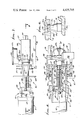
- FIG. 1 is a side elevation view of apparatus embodying the invention
- FIG. 2 is a section taken in elevation on lines 2--2 of FIG. 1;
- FIG. 3 is an end view taken in elevation on lines 3--3 of FIG. 1;
- FIG. 4 is a section taken on lines 4--4 of FIG. 1;
- FIG. 5 is an elevation taken in section on lines 5--5 of FIG. 4;
- FIG. 6 is an enlarged view showing reception of a gaging part between thread flanks
- FIG. 7 is a view like FIG. 4, but showing a modification
- FIG. 8 is a section on lines 8--8 of FIG. 7;
- FIG. 9 is a modified thread section.
- a portable gaging tool or instrument is indicated at 10, for gaging the thread or shoulder of a workpiece. While various workpieces are contemplated, the example shown comprises a pipe 11 the box end 11a of which has an internal thread 12.
- the thread may have various forms, one example being shown in FIG. 4 as a single-step thread. A two-step thread is seen at 13a and 13b in FIG. 9, the pipe box end indicated at 13.
- the thread may also take the form as shown in U.S. Pat. No. 3,989,284 to Blose, the tool 10 having particularly advantageous utility for gaging such a thread form.
- FIG. 6 is an example of such a thread 14 characterized as having semi-dovetail or undercut flanks 14a and 14b which face one another.
- the pipe axis appears at 15.
- the tool 10 includes a support, generally indicated at 16, the support in turn including a datum structure adapted to fit against a workpiece shoulder which faces generally in the direction of pipe axis 15.
- the illustrated datum structure comprises a first plate 17 which is recessed at 17a, and which has a frusto-conical internal shoulder 17b adapted to receive the terminal 11b of the pipe box end 11a.
- That terminal typically has a frusto-conical external shoulder 11c which closely interfits plate shoulder 17b, so that the plate 17 is approximately centered relative to the pipe and its axis, whereby the tool extends coaxially relative to the pipe when "made-up" to the pipe end terminal.
- This construction assures or enhances accuracy of thread gaging, both radially and axially, as will appear.
- the illustrated support 16 also includes a second plate 18 co-axially spaced from the first plate and connected to the latter as via connector members 19 spaced about axis 15.
- the plates 17 and 18 extend generally normal to axis 15, whereas members 19 extend generally in the direction of axis 15.
- Members 19 may be attached to the plates as by fasteners seen at 20 in FIG. 1.
- a handle 21 is made integral with one member 19 so that the tool may be easily transported to different pipe locations, and quickly coupled to the pipe ends in the manner described and to be described.
- the support 16 may also be regarded as including axially elongated tube 22 extending between the plates, and tubular plugs 23 and 24 respectively attaching the opposite ends of the tube to the plates 17 and 18.
- the plugs include shanks 23a and 24a extending through plate bores, heads 23b and 24b engaging the plate sides, and threaded portions 23c and 24c interfitting corresponding tube threads.
- Holder means is also provided to releasably connect the support 16 to the workpiece, or pipe.
- the holder means typically includes a clamp located for engagement with a radially presented surface of the workpiece, and actuator means to urge the clamp into engagement with the workpiece surface and also to simultaneously urge the datum structure into engagement with the workpiece shoulder 11c.
- a locating shoulder may be at the end of the pipe, or spaced from the end of the pipe. See annular shoulders 26-28 in FIG. 9, for example.
- the illustrated holder means generally designated at 30 includes a clamp 31 located within the pipe for engagement with radially presented bore surface 32 of the pipe.
- the clamp includes a collet 33 having three outwardly crowned jaws 34 respectively mounted on axially extending spring arms 35 spaced about axis 15, so as to be resiliently outwardly deflectible to clampingly engage bore 32.
- the arms extend from a base 36 slidably mounted on axially extending actuator rod 37. That rod extends through the tube 22 and through plugs 23 and 24, so as to be sildably mounted or carried by those plugs.
- Spring or Belleville washers 38 are also mounted on the rod and are located between the base 36 and the head 24b of plug 24, in order to be compressed so as to exert force to facilitate interfitting of the datum plate against the pipe terminal in response to actuation of the clamp, as will appear.
- the actuator means referred to above may advantageously include the rod 37 and a pusher 43 mounted on that rod to urge the jaws toward and into clamping engagement with the pipe bore in response to relative axial displacement of the rod, i.e. in a relatively rightward direction in FIG. 4.
- an exposed handle 40 coupled to the rightward end of that rod may be displaced to effect rod displacement.
- the handle may have threaded coupling at 41 to the rod, and also apply reaction load exerted on the plate 18 via washer 42, so that rotation of the handle urges the rod to the right. This serves to draw the pusher 43 to the right, exerting radially outward force on the jaws via coupling balls 44 carried by the pusher and engaging jaw ramps 45. Washer 46 and nut 47 retain the pusher 43 on the left end of rod 37.
- the jaws are crowned and carried by arms 35 to allow slight cantilever rocking thereof as they are urged into clamping engagment with the pipe bore.
- the Belleville springs allow leftward axial movement of plug 24 and datum plate 17 toward the base 36 after the clamp is anchored in position, whereby the datum plate can completely interfit the pipe terminal as the actuator handle is further rotated.
- the "crowning" of the jaws allows rocking thereof, when set, to the extent necessary to accommodate aligning and interfitting of the datum plate and pipe terminal shoulders 17b and 11c.
- a compression spring 48 on the rod between the pusher 43 and base 36 urges the pusher and rod leftwardly, to maintain the washer 42 compressed between handle 40 and plate 18.
- At least one gaging contact part 50 is carried for axial and radial movement in the space 51 between successive thread flights, to be engageable with axially opposite thread flanks. See flanks 14a and 14b in FIG. 6, for example.
- That gaging part may have a full or partial ball surface, and in FIG. 6 it has a first surface 50a which is annular about radial axis 51, and a second surface 50b which is radially outwardly dome shaped and is centrally intersected by axis 51.
- Surface 50a is outwardly convex in planes which contain axis 51, so as to be adapted to have point contact with the thread flanks; thus, the distance between flanks 14a and 14b may be accurately determined, that distance for example varying along the thread length as in the above referenced Blose thread.
- Surface 50b is convex in the radially outward direction of axis 51, so as to be adapted to have point contact with the pipe surface 53 between the roots of the thread flights, for accurate root-depth gaging purposes.
- the thread crests 53a may be similarly engaged, for gaging.
- the gaging part 50 is mounted on a radially outwardly projection pedestal 54 which is in turn supported on a carriage.
- the curvature of convex surface 50a is substantially less than the curvature surface 50a in axial radial planes.
- the carriage generally indicated at 56, includes a first section movable axially, and a second section movable radially; further, the gaging contact part 50 and pedestal 54 are mounted on one of the carriage sections that is carried by the other carriage section, the latter being movable independently of the former.
- the illustrated axially movable first section generally indicated at 57 is mounted via bearing 58 on the guide tube 22 so as to be movable axially thereon; also bearing 58 accommodate rotation of first section 57 on and about tube 22.
- Section 57 may also be tubular and extend coaxially with tube 22.
- the illustrated radially movable second section generally indicated at 59 is mounted via a linear bearing (indicated at 90 within housing 60) on the first carriage section, between plates 17 and 18.
- Housing 60 is radially movable, and axially movable relative to axis 15.
- the second section includes four frame members 61 which extend parallel to axis 51, and on opposite sides thereof, into the pipe, via openings 17d in plate 17.
- Two contact gaging parts which are typically alike, are respectively carried by thickened portions 61a of the frame members 61, as seen in FIG. 4, so as to project radially outwardly, at opposite sides of axis 15. Accordingly, a selected one of the two gaging parts may be displaced radially into the space between successive thread flights, depending upon the direction of radial movement of the second carriage section.
- the latter may be manually manipulated, for example, by grasping the second carriage. Automatic means to displace one or both carriage sections may be provided.
- Axial displacement of the second carriage also moves it and the first carriage along the guide tube 22, to position the gaging parts relative to thread flanks selected for gaging.
- the use of two gaging parts, diametrically opposed, enables measurements on opposite sides of the pipe to determine the geometrical center line of the pipe. This can be important should the pipe terminal not be precisely normal to the pipe axis. Also, skewing of the instrument axis relative to the pipe axis can be detected.
- radial movement of section 59 is independent of axial movement of section 57, for maximum gaging accuracy.
- Such means may notably include axial encoder 65 and radial encoder 66.
- the former is shown in FIG. 1 to include a plunger 67 which is urged against the face 68 of datum plate 17 by a spring in a cylinder 69 within which the plunger is slidable. Since section 57 is rotatable about axis 15, the plate 17 provides annular extent about axis 15 for engagement with plunger 67.
- a suitable magnetic encoding curcuit is located within the cylinder 69, as for example may include a linear differential transformer, with linear voltage output.
- the output of that circuit, indicated at lead 70, is transmitted to circuitry 71 which includes a computer and which appropriately digitizes the output of the transformer, for comparison with ideal thread flank position data, and comparative readout at 72, for example.
- circuitry 71 which includes a computer and which appropriately digitizes the output of the transformer, for comparison with ideal thread flank position data, and comparative readout at 72, for example.
- the encoder accurately senses the different positions of the thread flanks that a gaging part 50 engages.
- a switch 73 in lead 71 may be closed whenever the position of the gaging part in engagement with a thread flank is to be encoded and transmitted to the computer.
- the radial encoder 66 shown in FIG. 4 includes a plunger 76 which is urged against a stop 78 on radially movable housing 60 by a spring in a cylinder 79 within which a portion of the plunger is slidable. That cylinder is attached to axially movable section 57 so as not to be radially movable.
- a suitable magnetic encoding circuit is located within the housing 79, and the circuit output on lead 80 is transmitted to computer 71 when switch 81 is closed. Such output is compared in the computer with ideal thread flank radial dimension data (which may vary along the thread, for example). Thread crest and root data may also be transmitted to the computer. Readout is obtained at 72, as previously described.
- the modified portable tool 110 is adapted to gage a workpiece thread or shoulder that is radially outwardly exposed, as for example external thread 112 on pin end 111a of pipe 111.
- that thread may have various forms, one example being the single-step thread shown in FIGS. 7 and 8.
- the thread may take the form as shown in Blose U.S. Pat. No. 3,989,284 mentioned above.
- the tool 110 includes a support, generally indicated at 116, the latter including datum structure adapted to fit against the end of pipe 112; for example, datum plate 117 is recessed at 117a to have frusto-conical internal shoulder 117b to receive the terminal 111b of the pipe pin end 111a. That terminal has a frusto-conical external shoulder 111c which closely and telescopically interfits plate shoulder 117b, so that the support plate is precisely centered relative to the pipe and its axis 115. As before, accuracy and precision of pipe thread or shoulder gaging is thereby made possible.
- Support 116 also may include a second plate (not shown) like plate 18 described above, and connected to plate 117 via connector members 119 spaced about axis 115.
- a suitable handle for the tool may be provided, and corresponding to handle 21 in FIG. 1.
- the support 116 includes axially elongated tube 122 extending between the described first and second plates. Plug 124 with shank 124a extends through plate 117, these parts 122 and 124 correspond to parts 22 and 24 in FIG. 4.
- Holder means 130 is also provided, as before, to releasably connect the support 116 to the workpiece, such as pipe 110.
- That holder means typically includes a clamp 131 and actuator means, functioning as described above. Accordingly, corresponding parts are given the same numbers, with the addition of a "1" before the corresponding number.
- At least one gaging contact part 150 is carried for axial and radial movement in the space between 151 between successive external thread flights to be engageable with opposite thread flanks. See flanks 114a and 114b. That gaging part may have a construction the same as, or similar to, that of part 50, described above; however, the part 150 is instead presented radially inwardly rather than radially outwardly. Part 150 is carried on pedestal 154. Thus, thread crests and roots, as well as flanks, may be accurately gaged, and axially and radially facing shoulders on the pipe or workpiece may also be precisely gaged. Two gages 150, at opposite sides of axis 115, are shown and may be alternately used for rapid gaging purposes (i.e. so as not to require 180° rotation of one gage 150 and the carriage therefor, about axis 115, to gage the thread or shoulder extent at the opposite side of axis 115).
- the illustrated carriage 156 for the gaging part 150 includes first and second sections 157 and 159 generally corresponding in structure and mode of operation to respective sections 57 and 59 described above.
- the radially movable section 159 is shown in FIG. 7 as including yoke arms 159a movable radially and perpendicularly to the plane of FIG. 7, there being bearings 190 between such arms and guide part 191 of section 157. The latter is movable axially relative to axis 115, as before.
- Second section 159 includes frame members 161 (corresponding to members 61 in FIG. 4) which extend parallel to axis 115, and at opposite sides of the latter to carry two gaging parts 150 and their pedestals, as shown, exteriorly of the pipe pin end.
- An annular ring 193 may be provided at the free ends of frame members 161, to protect the gaging parts 150 against inadvertently striking against pipe upset shoulder 194.
- Radial encoder 166 is shown to include plunger 176 urged against stop 177 on radially movable housing or yoke 159 by a spring within cylinder 179 within which a portion of the plunger is slidable. That cylinder is attached to axially movable section 157 so as not to be radially movable toward and away from axis 115.
- a guiding handle 197 is provided on the section 159, with a sidewardly presented and graspable knurled ring 197a, to facilitate accurate axial and radial guided travel of the gaging part 150.
Landscapes
- Physics & Mathematics (AREA)
- General Physics & Mathematics (AREA)
- A Measuring Device Byusing Mechanical Method (AREA)
Abstract
Description
Claims (14)
Priority Applications (1)
| Application Number | Priority Date | Filing Date | Title |
|---|---|---|---|
| US06/243,867 US4425715A (en) | 1979-06-25 | 1981-03-16 | Thread gaging apparatus and method |
Applications Claiming Priority (2)
| Application Number | Priority Date | Filing Date | Title |
|---|---|---|---|
| US5180279A | 1979-06-25 | 1979-06-25 | |
| US06/243,867 US4425715A (en) | 1979-06-25 | 1981-03-16 | Thread gaging apparatus and method |
Related Parent Applications (1)
| Application Number | Title | Priority Date | Filing Date |
|---|---|---|---|
| US5180279A Continuation | 1979-06-25 | 1979-06-25 |
Publications (1)
| Publication Number | Publication Date |
|---|---|
| US4425715A true US4425715A (en) | 1984-01-17 |
Family
ID=26729838
Family Applications (1)
| Application Number | Title | Priority Date | Filing Date |
|---|---|---|---|
| US06/243,867 Expired - Fee Related US4425715A (en) | 1979-06-25 | 1981-03-16 | Thread gaging apparatus and method |
Country Status (1)
| Country | Link |
|---|---|
| US (1) | US4425715A (en) |
Cited By (8)
| Publication number | Priority date | Publication date | Assignee | Title |
|---|---|---|---|---|
| US4474496A (en) * | 1983-01-24 | 1984-10-02 | W. R. Grace & Co. | Compact dryer for two web stretches |
| US4559711A (en) * | 1982-06-23 | 1985-12-24 | Hydril Company | Workpiece gaging apparatus |
| US4706360A (en) * | 1986-05-13 | 1987-11-17 | Morton Thiokol, Inc. | Thread gage |
| US6370786B2 (en) * | 1998-07-17 | 2002-04-16 | Masato Ishii | Measuring method and apparatus thereof |
| US20080296894A1 (en) * | 2007-05-29 | 2008-12-04 | Grant Prideco, L.P. | Oilfield threaded connections |
| JP2014502351A (en) * | 2010-11-26 | 2014-01-30 | ヴァルレック・マンネスマン・オイル・アンド・ガス・フランス | Inspection method and apparatus for tubular connection thread used in oil industry |
| US8881420B2 (en) | 2012-02-01 | 2014-11-11 | Randall Jeffrey COLOMBO | Method and apparatus for measuring an opening |
| US10495502B2 (en) | 2015-09-23 | 2019-12-03 | Texas Instruments Incorporated | Ultrasonic flow meter auto-tuning for reciprocal operation of the meter |
Citations (12)
| Publication number | Priority date | Publication date | Assignee | Title |
|---|---|---|---|---|
| DE390036C (en) | 1922-05-14 | 1924-02-12 | Zeiss Carl Fa | Device for testing thread pitches |
| US1614448A (en) | 1920-02-21 | 1927-01-11 | Westinghouse Electric & Mfg Co | Apparatus for determining the accuracy of gears and hobs |
| DE483605C (en) | 1926-05-07 | 1929-10-03 | Fried Krupp Akt Ges | Pitch gauge for internal thread |
| US1864634A (en) | 1929-11-27 | 1932-06-28 | Emmitt Sharp | Saw gauge |
| US1879398A (en) | 1929-06-22 | 1932-09-27 | George E Mirfield | Gauge for sizing internal threads |
| US2233626A (en) | 1939-10-20 | 1941-03-04 | Nat Tube Co | Gauge |
| US3047960A (en) | 1959-10-30 | 1962-08-07 | American Iron And Machine Work | Method and apparatus for inspecting threads and cylinders |
| US3091867A (en) | 1960-11-30 | 1963-06-04 | Jr Robert E Ryan | Thread pitch gage |
| US3590492A (en) | 1969-07-14 | 1971-07-06 | Johnson Co Gage | Screw thread gage with segmental and envelope gaging means |
| DE2200432A1 (en) | 1971-01-08 | 1972-10-05 | Secretary Trade Ind Brit | Device for measuring the thread pitch error of screws |
| US3812591A (en) | 1972-05-08 | 1974-05-28 | Colt Ind Operating Corp | Multifunction thread gage |
| US3989284A (en) | 1975-04-23 | 1976-11-02 | Hydril Company | Tubular connection |
-
1981
- 1981-03-16 US US06/243,867 patent/US4425715A/en not_active Expired - Fee Related
Patent Citations (12)
| Publication number | Priority date | Publication date | Assignee | Title |
|---|---|---|---|---|
| US1614448A (en) | 1920-02-21 | 1927-01-11 | Westinghouse Electric & Mfg Co | Apparatus for determining the accuracy of gears and hobs |
| DE390036C (en) | 1922-05-14 | 1924-02-12 | Zeiss Carl Fa | Device for testing thread pitches |
| DE483605C (en) | 1926-05-07 | 1929-10-03 | Fried Krupp Akt Ges | Pitch gauge for internal thread |
| US1879398A (en) | 1929-06-22 | 1932-09-27 | George E Mirfield | Gauge for sizing internal threads |
| US1864634A (en) | 1929-11-27 | 1932-06-28 | Emmitt Sharp | Saw gauge |
| US2233626A (en) | 1939-10-20 | 1941-03-04 | Nat Tube Co | Gauge |
| US3047960A (en) | 1959-10-30 | 1962-08-07 | American Iron And Machine Work | Method and apparatus for inspecting threads and cylinders |
| US3091867A (en) | 1960-11-30 | 1963-06-04 | Jr Robert E Ryan | Thread pitch gage |
| US3590492A (en) | 1969-07-14 | 1971-07-06 | Johnson Co Gage | Screw thread gage with segmental and envelope gaging means |
| DE2200432A1 (en) | 1971-01-08 | 1972-10-05 | Secretary Trade Ind Brit | Device for measuring the thread pitch error of screws |
| US3812591A (en) | 1972-05-08 | 1974-05-28 | Colt Ind Operating Corp | Multifunction thread gage |
| US3989284A (en) | 1975-04-23 | 1976-11-02 | Hydril Company | Tubular connection |
Cited By (10)
| Publication number | Priority date | Publication date | Assignee | Title |
|---|---|---|---|---|
| US4559711A (en) * | 1982-06-23 | 1985-12-24 | Hydril Company | Workpiece gaging apparatus |
| US4474496A (en) * | 1983-01-24 | 1984-10-02 | W. R. Grace & Co. | Compact dryer for two web stretches |
| US4706360A (en) * | 1986-05-13 | 1987-11-17 | Morton Thiokol, Inc. | Thread gage |
| US6370786B2 (en) * | 1998-07-17 | 2002-04-16 | Masato Ishii | Measuring method and apparatus thereof |
| US20080296894A1 (en) * | 2007-05-29 | 2008-12-04 | Grant Prideco, L.P. | Oilfield threaded connections |
| US9599259B2 (en) * | 2007-05-29 | 2017-03-21 | Vam Usa, Llc | Oilfield threaded connections |
| JP2014502351A (en) * | 2010-11-26 | 2014-01-30 | ヴァルレック・マンネスマン・オイル・アンド・ガス・フランス | Inspection method and apparatus for tubular connection thread used in oil industry |
| US9140530B2 (en) | 2010-11-26 | 2015-09-22 | Vallourec Oil And Gas France | Method and device for inspecting a threading of a tubular connection used in the oil industry |
| US8881420B2 (en) | 2012-02-01 | 2014-11-11 | Randall Jeffrey COLOMBO | Method and apparatus for measuring an opening |
| US10495502B2 (en) | 2015-09-23 | 2019-12-03 | Texas Instruments Incorporated | Ultrasonic flow meter auto-tuning for reciprocal operation of the meter |
Similar Documents
| Publication | Publication Date | Title |
|---|---|---|
| EP0508686B1 (en) | Calibration device for machine | |
| US4524524A (en) | Gage for measuring diameters | |
| US4425715A (en) | Thread gaging apparatus and method | |
| CN217799141U (en) | Drilling guide device for handheld drilling machine | |
| US4553337A (en) | Thread gauge for measuring thread pitch diameters | |
| CN105479271A (en) | Sphere center centring and positioning device for five-axis machine tool error synchronous detection mechanism | |
| GB2052065A (en) | Thread Gauging Apparatus And Method | |
| CN104551789B (en) | Indexing fixture | |
| CN204963740U (en) | Inner diameter measurement device | |
| US2565140A (en) | Height gauge | |
| CN216846037U (en) | Measuring tool for measuring chamfer angle by adopting telescopic measuring head | |
| JP2583669Y2 (en) | Rail joint jig for linear guide device | |
| US3067520A (en) | Groove and thread checking gauge | |
| US4352246A (en) | Tracer head for machine tools | |
| US3882604A (en) | Spline measuring unit | |
| US5020229A (en) | Apparatus and method for measuring screw threads | |
| US3043639A (en) | Fluid pressure cylinder | |
| CN205655753U (en) | Inside caliper | |
| US3054189A (en) | Adapter for dial indicator gauge | |
| EP0097537A2 (en) | Workpiece gaging apparatus | |
| CN208936925U (en) | The conical surface is apart from special gauge | |
| US4989331A (en) | Gage | |
| CN218363333U (en) | Pre-clamping device, tool clamp and machining center | |
| CN220170097U (en) | Micrometer for measuring depth of groove | |
| CN211717313U (en) | Aperture gauge |
Legal Events
| Date | Code | Title | Description |
|---|---|---|---|
| FEPP | Fee payment procedure |
Free format text: PAYOR NUMBER ASSIGNED (ORIGINAL EVENT CODE: ASPN); ENTITY STATUS OF PATENT OWNER: LARGE ENTITY |
|
| MAFP | Maintenance fee payment |
Free format text: PAYMENT OF MAINTENANCE FEE, 4TH YEAR, PL 96-517 (ORIGINAL EVENT CODE: M170); ENTITY STATUS OF PATENT OWNER: LARGE ENTITY Year of fee payment: 4 |
|
| MAFP | Maintenance fee payment |
Free format text: PAYMENT OF MAINTENANCE FEE, 8TH YEAR, PL 96-517 (ORIGINAL EVENT CODE: M171); ENTITY STATUS OF PATENT OWNER: LARGE ENTITY Year of fee payment: 8 |
|
| FEPP | Fee payment procedure |
Free format text: MAINTENANCE FEE HAS ALREADY BEEN PAID. REFUND IS SCHEDULED (ORIGINAL EVENT CODE: F160); ENTITY STATUS OF PATENT OWNER: LARGE ENTITY |
|
| FEPP | Fee payment procedure |
Free format text: MAINTENANCE FEE REMINDER MAILED (ORIGINAL EVENT CODE: REM.); ENTITY STATUS OF PATENT OWNER: LARGE ENTITY |
|
| LAPS | Lapse for failure to pay maintenance fees | ||
| FP | Lapsed due to failure to pay maintenance fee |
Effective date: 19960117 |
|
| AS | Assignment |
Owner name: CHASE BANK OF TEXAS, NATIONAL ASSOC., AS AGENT, TE Free format text: SECURITY INTEREST;ASSIGNOR:HYDRIL COMPANY;REEL/FRAME:009123/0016 Effective date: 19980323 |
|
| AS | Assignment |
Owner name: HYDRIL COMPANY, TEXAS Free format text: RELEASE OF LIEN;ASSIGNOR:CHASE BANK OF TEXAS, NATIONAL ASSOCIATION;REEL/FRAME:014734/0860 Effective date: 20040604 |
|
| STCH | Information on status: patent discontinuation |
Free format text: PATENT EXPIRED DUE TO NONPAYMENT OF MAINTENANCE FEES UNDER 37 CFR 1.362 |