US4413482A - Cam-support for a knitting machine - Google Patents
Cam-support for a knitting machine Download PDFInfo
- Publication number
- US4413482A US4413482A US06/270,966 US27096681A US4413482A US 4413482 A US4413482 A US 4413482A US 27096681 A US27096681 A US 27096681A US 4413482 A US4413482 A US 4413482A
- Authority
- US
- United States
- Prior art keywords
- cam
- cams
- push
- needles
- support
- Prior art date
- Legal status (The legal status is an assumption and is not a legal conclusion. Google has not performed a legal analysis and makes no representation as to the accuracy of the status listed.)
- Expired - Fee Related
Links
Images

Classifications
-
- D—TEXTILES; PAPER
- D04—BRAIDING; LACE-MAKING; KNITTING; TRIMMINGS; NON-WOVEN FABRICS
- D04B—KNITTING
- D04B15/00—Details of, or auxiliary devices incorporated in, weft knitting machines, restricted to machines of this kind
- D04B15/66—Devices for determining or controlling patterns ; Program-control arrangements
- D04B15/82—Devices for determining or controlling patterns ; Program-control arrangements characterised by the needle cams used
Definitions
- the present invention relates to a cam-support for a knitting machine for the entrainment of the push-rods, respectively of the needles, according to the so-called "three way” technique, comprising several lifting cams intended to entrain the abutment surfaces of the push-rods respectively of the needles, at several different selection points, so that the needles operate either in the knit tuck or miss position.
- French Pat. No. 1 500 569 describes a cam-support comprising two pairs of lifting cams intended to cooperate with the abutment surfaces of the push-rods for the two directions of movement of the cam-support respectively.
- the push-rods are pre-selected in order to be entrained either by the first cam, in order to raise the needles which are entrained by cams in order to operate in the knit position, or to pass below the first cam in order to be released in front of the second cam, in order to be entrained by this second cam by raising the needles which are entrained by a cam in order to operate in the tuck position.
- This cam-support also comprises two movable cams cooperating with the abutment surfaces of the needles, one of these cams being able to move longitudinally and the other to rotate in the opposite direction to the action of the abutment surfaces of the needles.
- this cam-support cannot be used in a double system knitting machine, on account of the system for the selection of the push-rods. In fact, once the push-rods have been selected, they cannot be selected a second time at the time of the same passage of the carriage.
- the Applicant has developed an electromechanical device for individual selection of the needles facilitating a very rapid selection of the needles by means of a device mounted on the cam-support carriage and comprising electromagnets controlling ratchets.
- This device is described in particular in French Pat. No. 2 436 207.
- the present invention intends to take advantage of the rapidity, flexibility and of the possibilities of remotely controlling this selection device by means of a programme recorded on a magnetic tape or other recording support, in order to produce a cam-support which is as simple and compact as possible making it possible to produce a multiple system knitting machine, without any limitations.
- the cam-support according to the invention is characterised by the fact that it comprises at least one arrangement of lifting cams comprising two lifting cams located immediately one after the other and each comprising two opposed ramps and a third lifting cam located between the adjacent ramps of the two first cams, an empty space being provided below this third cam, said space being connected to two channels limited on one side by the adjacent ramps of the two first cams, so that a push-rod, respectively a needle, selected before the arrival of an outer end of said first cams, is entrained by one of said first cams in the direction of movement of the cam-support and by the third cam and operates in the knit position. Whereas a push-rod, respectively a needle, selected when said empty space arrives approximately opposite said push-rod, respectively needle, is not entrained by the third cam and operates in the tuck position.
- the needles are pushed by push-rods and it is the abutment surfaces of these push-rods which are or are not engaged, at right angles to the plane of the cam-support, in the trajectory of the cams, but it would be possible to dispense with the push-rods for selecting the needles directly in the manner of the pins.
- this type of cam-support may be used both with a circular knitting machine as well as with a straight knitting machine.
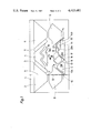
- FIG. 1 shows a cam-support as well as the various possible trajectories of the push-rods at the time of movement of the cam-support from right to left.
- FIG. 2 shows the same cam-support and the possible trajectories of the push-rods at the time of movement of the cam-support from left to right.
- the cam-support illustrated is intended to be mounted, in manner known per se, on a carriage moving along a needle row containing needles and push-rods, the needle row or rows are also accompanied by an auxiliary needle row perpendicular to the main needle row and containing auxiliary push-rods intended to cooperate with a selection device, such as that described in French Pat. No. 2 436 207.
- the cam-support is constituted by a plate 1 on which knitting cams are mounted in manner known per se.
- the cams 2 to 6 are fixed cams intended to cooperate with the abutment surfaces 7 of the needles.
- the cams 8 and 9 which are also fixed cooperate on the one hand with the abutment surfaces of the needles for their alignment and on the other hand with the abutment surfaces 10 of the push-rods for their knocking-over.
- One position of a needle 11 and its associated push-rod 12 has been illustrated by way of example, in dot dash line.
- the cam-support also comprises two lifting cams 13 and 14 which are fixed and each comprise two main opposed ramps 13a,13b respectively 14a and 14b, these cams 13 and 14 being located one beside the other, so that the lower ends of the ramps 13b and 14a join. However, they could be separated by a short space.
- a third lifting cam 15 which is also fixed is mounted between the two cams 13 and 14. This cam 15 is separated from the cams 13 and 14 by two channels 16 and 17 joining in an empty space 18, above the junction point of the cams 13 and 14.
- the cam-support illustrated is also equipped with a system for transferring stitches and to this end comprises a cam 19, for the needles, able to be put into or out of operation, in manner known per se, by moving at right angles to the plane of the drawing and a cam 20, which is also movable, which may be either a cam which is able to be put into or out of operation or an automatic cam which can be retracted by the abutment surface of the push-rods, when the cam-support moves from right to left, in the direction of arrow F1, the cam 20 comprising a ramp 20a on its side for this purpose.
- the push-rod selected opposite the space 18, follows the trajectory D approximately, the needle being guided by the ramp 19a.
- the needle thus operates for transferring a stitch (needle which picks up).
- the cam 20 is thus inoperative, i.e. retracted, according to its design.
- the push-rod follows one of the trajectories illustrated in this figure. If the selection takes place at the end of the cam 14, the abutment surface 10 of the push-rod follows the trajectory A' and the needle operates "in the knit position". If the selection takes place solely opposite the space 18, the abutment surface 10 follows the trajectory B' and the needle operates "in the tuck position”. If the push rod is not selected, it is not entrained by the cams. If, when the push-rod is selected on reaching the cam 14, the cam 19 is operative, the abutment surface 7 of the needle is completely engaged by the cams 4 and 19 and follows the trajectory E. The needle thus operates for transferring (needle which gives up stitches).
Landscapes
- Engineering & Computer Science (AREA)
- Textile Engineering (AREA)
- Knitting Machines (AREA)
Abstract
Description
Claims (1)
Applications Claiming Priority (2)
| Application Number | Priority Date | Filing Date | Title |
|---|---|---|---|
| CH4608/80 | 1980-06-16 | ||
| CH460880A CH636657A5 (en) | 1980-06-16 | 1980-06-16 | Cam holder for knitting. |
Publications (1)
| Publication Number | Publication Date |
|---|---|
| US4413482A true US4413482A (en) | 1983-11-08 |
Family
ID=4279274
Family Applications (1)
| Application Number | Title | Priority Date | Filing Date |
|---|---|---|---|
| US06/270,966 Expired - Fee Related US4413482A (en) | 1980-06-16 | 1981-06-05 | Cam-support for a knitting machine |
Country Status (9)
| Country | Link |
|---|---|
| US (1) | US4413482A (en) |
| JP (1) | JPS5725451A (en) |
| CH (1) | CH636657A5 (en) |
| DD (1) | DD159651A5 (en) |
| DE (2) | DE8116244U1 (en) |
| ES (1) | ES8204004A1 (en) |
| FR (1) | FR2484479B1 (en) |
| GB (1) | GB2080344B (en) |
| IT (2) | IT8122075V0 (en) |
Cited By (7)
| Publication number | Priority date | Publication date | Assignee | Title |
|---|---|---|---|---|
| US4470274A (en) * | 1982-04-28 | 1984-09-11 | Shima Idea Center Co., Ltd. | Flat knitting machine |
| US4559791A (en) * | 1983-11-07 | 1985-12-24 | Universal Maschinenfabrik Dr. Rudolf Schieber Gmbh & Co., Kg | Flat knitting machine with selective needle selection |
| US4718255A (en) * | 1985-06-25 | 1988-01-12 | Veb Kombinat Textima | Combined knitting and loop transfer cam arrangement for knitting machines |
| ES2167126A1 (en) * | 1998-11-06 | 2002-05-01 | Juberca S A | Circular machine for type of knitting uses integrated sets and has needles and jacks unified axially which have at least two heel pieces, of which one is concealable |
| ES2187367A1 (en) * | 2001-09-05 | 2003-06-01 | Quantum Knitting Technologies | Multiple levers based mesh production transfer needles selector includes mobile and static levers in a specific configuration |
| CN102021735A (en) * | 2010-12-29 | 2011-04-20 | 宁波慈星股份有限公司 | Stitch transfer cam of computer knitting machine |
| CN110670226A (en) * | 2019-09-29 | 2020-01-10 | 福建睿能科技股份有限公司 | Knitting cam system and flat knitting machine |
Families Citing this family (4)
| Publication number | Priority date | Publication date | Assignee | Title |
|---|---|---|---|---|
| DE3138986C2 (en) * | 1981-09-30 | 1984-01-19 | Universal Maschinenfabrik Dr. Rudolf Schieber GmbH & Co KG, 7081 Westhausen | Single or multiple lock unit for knitting machines |
| DE3315283C2 (en) * | 1982-04-28 | 1994-07-28 | Shima Seiki Mfg | Flat knitting machine |
| DE3433628C2 (en) * | 1984-09-13 | 1986-12-18 | H. Stoll Gmbh & Co, 7410 Reutlingen | Lock system for flat knitting machines and method for the combined formation and transfer of stitches on flat knitting machines |
| EP0217432B1 (en) * | 1985-09-04 | 1988-11-17 | Atelier De Construction Steiger S.A. | Cam unit for a flat bed knitting machine, and knitting machine equipped with said cam unit |
Citations (4)
| Publication number | Priority date | Publication date | Assignee | Title |
|---|---|---|---|---|
| US236062A (en) * | 1880-12-28 | Knitting-machine | ||
| US242129A (en) * | 1881-05-31 | howird | ||
| US1992982A (en) * | 1931-09-14 | 1935-03-05 | Hyman M Zippel | Knitting machine |
| SU711199A1 (en) * | 1978-01-30 | 1980-01-25 | Конструкторско-Проектно-Технологический Институт Бытового Обслуживания | Needle cam of flat-knitting machine |
-
1980
- 1980-06-16 CH CH460880A patent/CH636657A5/en not_active IP Right Cessation
-
1981
- 1981-05-29 GB GB8116428A patent/GB2080344B/en not_active Expired
- 1981-06-01 DE DE8116244U patent/DE8116244U1/en not_active Expired
- 1981-06-01 DE DE19813121718 patent/DE3121718A1/en not_active Ceased
- 1981-06-05 US US06/270,966 patent/US4413482A/en not_active Expired - Fee Related
- 1981-06-05 FR FR8111201A patent/FR2484479B1/en not_active Expired
- 1981-06-12 IT IT8122075U patent/IT8122075V0/en unknown
- 1981-06-12 IT IT22289/81A patent/IT1136744B/en active
- 1981-06-15 ES ES503063A patent/ES8204004A1/en not_active Expired
- 1981-06-15 DD DD81230804A patent/DD159651A5/en unknown
- 1981-06-16 JP JP9166681A patent/JPS5725451A/en active Pending
Patent Citations (4)
| Publication number | Priority date | Publication date | Assignee | Title |
|---|---|---|---|---|
| US236062A (en) * | 1880-12-28 | Knitting-machine | ||
| US242129A (en) * | 1881-05-31 | howird | ||
| US1992982A (en) * | 1931-09-14 | 1935-03-05 | Hyman M Zippel | Knitting machine |
| SU711199A1 (en) * | 1978-01-30 | 1980-01-25 | Конструкторско-Проектно-Технологический Институт Бытового Обслуживания | Needle cam of flat-knitting machine |
Cited By (9)
| Publication number | Priority date | Publication date | Assignee | Title |
|---|---|---|---|---|
| US4470274A (en) * | 1982-04-28 | 1984-09-11 | Shima Idea Center Co., Ltd. | Flat knitting machine |
| US4559791A (en) * | 1983-11-07 | 1985-12-24 | Universal Maschinenfabrik Dr. Rudolf Schieber Gmbh & Co., Kg | Flat knitting machine with selective needle selection |
| US4718255A (en) * | 1985-06-25 | 1988-01-12 | Veb Kombinat Textima | Combined knitting and loop transfer cam arrangement for knitting machines |
| ES2167126A1 (en) * | 1998-11-06 | 2002-05-01 | Juberca S A | Circular machine for type of knitting uses integrated sets and has needles and jacks unified axially which have at least two heel pieces, of which one is concealable |
| ES2187367A1 (en) * | 2001-09-05 | 2003-06-01 | Quantum Knitting Technologies | Multiple levers based mesh production transfer needles selector includes mobile and static levers in a specific configuration |
| ES2187367B1 (en) * | 2001-09-05 | 2004-09-16 | Quantum Knitting Technologies, S.A. | CAMS DEVICE FOR SELECTION OF TRANSFER NEEDLES IN GENDER GENDER MACHINES. |
| CN102021735A (en) * | 2010-12-29 | 2011-04-20 | 宁波慈星股份有限公司 | Stitch transfer cam of computer knitting machine |
| CN110670226A (en) * | 2019-09-29 | 2020-01-10 | 福建睿能科技股份有限公司 | Knitting cam system and flat knitting machine |
| CN110670226B (en) * | 2019-09-29 | 2021-06-29 | 福建睿能科技股份有限公司 | Knitting cam system and flat knitting machine |
Also Published As
| Publication number | Publication date |
|---|---|
| FR2484479B1 (en) | 1985-07-19 |
| DD159651A5 (en) | 1983-03-23 |
| IT8122075V0 (en) | 1981-06-12 |
| CH636657A5 (en) | 1983-06-15 |
| DE3121718A1 (en) | 1982-02-25 |
| IT1136744B (en) | 1986-09-03 |
| ES503063A0 (en) | 1982-04-01 |
| IT8122289A0 (en) | 1981-06-12 |
| GB2080344B (en) | 1984-06-20 |
| GB2080344A (en) | 1982-02-03 |
| FR2484479A1 (en) | 1981-12-18 |
| JPS5725451A (en) | 1982-02-10 |
| ES8204004A1 (en) | 1982-04-01 |
| DE8116244U1 (en) | 1985-08-08 |
Similar Documents
| Publication | Publication Date | Title |
|---|---|---|
| US4214460A (en) | Flat knitting machine | |
| US4294085A (en) | Flat bed knitting machines | |
| US4413482A (en) | Cam-support for a knitting machine | |
| US4643003A (en) | Cam system and method for combined loop formation and transfer in flat-bed knitting machines | |
| US3913354A (en) | Design knitting machine with stitch transfer | |
| US4287727A (en) | Flat bed knitting machine | |
| JPS62125053A (en) | Traverse knitting machine | |
| US3340708A (en) | Knitting machine with electromagnetic needle selection mechanism | |
| US4662192A (en) | Flat knitting machine | |
| US4409801A (en) | Needle selecting method and apparatus in flat knitting machine | |
| EP1279758B1 (en) | Weft knitting machine with transferring mechanism and transferring method | |
| CS205106B2 (en) | Patterning device in knitting machines,especially of flat-bed types | |
| US3263453A (en) | Circular knitting machines | |
| US4197722A (en) | Knitting machine | |
| GB2133425A (en) | Electromagnetic selection device for knitting-machine | |
| US4141228A (en) | Pattern mechanism for a flat bed knitting machine | |
| US2444894A (en) | Multiple selection pattern mechanism | |
| US3158012A (en) | Knitting machines | |
| US4644763A (en) | Knitting machine with electromagnetic needle selection | |
| US3292395A (en) | Straight bar knitting machines | |
| US4147042A (en) | Selection mechanism of circular knitting-machine | |
| KR100768347B1 (en) | Flat knitting machine and nose movement method provided with nose movement mechanism | |
| KR100768345B1 (en) | Flat knitting machine with nose moving mechanism | |
| US2310070A (en) | Knitting machine and method | |
| US3225568A (en) | Hand-knitting machine |
Legal Events
| Date | Code | Title | Description |
|---|---|---|---|
| AS | Assignment |
Owner name: ATELIER DE CONSTRUCTION STEIGER S.A., 1891 VIONNAZ Free format text: ASSIGNMENT OF ASSIGNORS INTEREST.;ASSIGNOR:STEIGER GERARD;REEL/FRAME:003880/0644 Effective date: 19810601 Owner name: ATELIER DE CONSTRUCTION STEIGER S.A., A COMPANY O Free format text: ASSIGNMENT OF ASSIGNORS INTEREST;ASSIGNOR:STEIGER GERARD;REEL/FRAME:003880/0644 Effective date: 19810601 |
|
| MAFP | Maintenance fee payment |
Free format text: PAYMENT OF MAINTENANCE FEE, 4TH YEAR, PL 96-517 (ORIGINAL EVENT CODE: M170); ENTITY STATUS OF PATENT OWNER: SMALL ENTITY Year of fee payment: 4 |
|
| FEPP | Fee payment procedure |
Free format text: MAINTENANCE FEE REMINDER MAILED (ORIGINAL EVENT CODE: REM.); ENTITY STATUS OF PATENT OWNER: SMALL ENTITY |
|
| FEPP | Fee payment procedure |
Free format text: PAYOR NUMBER ASSIGNED (ORIGINAL EVENT CODE: ASPN); ENTITY STATUS OF PATENT OWNER: SMALL ENTITY |
|
| LAPS | Lapse for failure to pay maintenance fees | ||
| FP | Lapsed due to failure to pay maintenance fee |
Effective date: 19911110 |
|
| STCH | Information on status: patent discontinuation |
Free format text: PATENT EXPIRED DUE TO NONPAYMENT OF MAINTENANCE FEES UNDER 37 CFR 1.362 |