US4410024A - Apparatus and method of assembling barge fenders - Google Patents
Apparatus and method of assembling barge fenders Download PDFInfo
- Publication number
- US4410024A US4410024A US06/247,641 US24764181A US4410024A US 4410024 A US4410024 A US 4410024A US 24764181 A US24764181 A US 24764181A US 4410024 A US4410024 A US 4410024A
- Authority
- US
- United States
- Prior art keywords
- work piece
- saw
- work
- assembly
- barge
- Prior art date
- Legal status (The legal status is an assumption and is not a legal conclusion. Google has not performed a legal analysis and makes no representation as to the accuracy of the status listed.)
- Expired - Lifetime
Links
Images


Classifications
-
- B—PERFORMING OPERATIONS; TRANSPORTING
- B27—WORKING OR PRESERVING WOOD OR SIMILAR MATERIAL; NAILING OR STAPLING MACHINES IN GENERAL
- B27B—SAWS FOR WOOD OR SIMILAR MATERIAL; COMPONENTS OR ACCESSORIES THEREFOR
- B27B5/00—Sawing machines working with circular or cylindrical saw blades; Components or equipment therefor
- B27B5/16—Saw benches
- B27B5/22—Saw benches with non-feedable circular saw blade
- B27B5/228—Cross-cutting automatically laterally-fed travelling workpieces; Reducing lumber to desired lengths
-
- B—PERFORMING OPERATIONS; TRANSPORTING
- B23—MACHINE TOOLS; METAL-WORKING NOT OTHERWISE PROVIDED FOR
- B23P—METAL-WORKING NOT OTHERWISE PROVIDED FOR; COMBINED OPERATIONS; UNIVERSAL MACHINE TOOLS
- B23P19/00—Machines for simply fitting together or separating metal parts or objects, or metal and non-metal parts, whether or not involving some deformation; Tools or devices therefor so far as not provided for in other classes
- B23P19/04—Machines for simply fitting together or separating metal parts or objects, or metal and non-metal parts, whether or not involving some deformation; Tools or devices therefor so far as not provided for in other classes for assembling or disassembling parts
- B23P19/06—Screw or nut setting or loosening machines
-
- B—PERFORMING OPERATIONS; TRANSPORTING
- B27—WORKING OR PRESERVING WOOD OR SIMILAR MATERIAL; NAILING OR STAPLING MACHINES IN GENERAL
- B27B—SAWS FOR WOOD OR SIMILAR MATERIAL; COMPONENTS OR ACCESSORIES THEREFOR
- B27B5/00—Sawing machines working with circular or cylindrical saw blades; Components or equipment therefor
- B27B5/02—Sawing machines working with circular or cylindrical saw blades; Components or equipment therefor characterised by a special purpose only
-
- B—PERFORMING OPERATIONS; TRANSPORTING
- B27—WORKING OR PRESERVING WOOD OR SIMILAR MATERIAL; NAILING OR STAPLING MACHINES IN GENERAL
- B27M—WORKING OF WOOD NOT PROVIDED FOR IN SUBCLASSES B27B - B27L; MANUFACTURE OF SPECIFIC WOODEN ARTICLES
- B27M3/00—Manufacture or reconditioning of specific semi-finished or finished articles
- B27M3/0013—Manufacture or reconditioning of specific semi-finished or finished articles of composite or compound articles
- B27M3/0026—Manufacture or reconditioning of specific semi-finished or finished articles of composite or compound articles characterised by oblong elements connected laterally
- B27M3/0046—Manufacture or reconditioning of specific semi-finished or finished articles of composite or compound articles characterised by oblong elements connected laterally by rods or tie wires
-
- Y—GENERAL TAGGING OF NEW TECHNOLOGICAL DEVELOPMENTS; GENERAL TAGGING OF CROSS-SECTIONAL TECHNOLOGIES SPANNING OVER SEVERAL SECTIONS OF THE IPC; TECHNICAL SUBJECTS COVERED BY FORMER USPC CROSS-REFERENCE ART COLLECTIONS [XRACs] AND DIGESTS
- Y10—TECHNICAL SUBJECTS COVERED BY FORMER USPC
- Y10T—TECHNICAL SUBJECTS COVERED BY FORMER US CLASSIFICATION
- Y10T29/00—Metal working
- Y10T29/51—Plural diverse manufacturing apparatus including means for metal shaping or assembling
- Y10T29/5124—Plural diverse manufacturing apparatus including means for metal shaping or assembling with means to feed work intermittently from one tool station to another
-
- Y—GENERAL TAGGING OF NEW TECHNOLOGICAL DEVELOPMENTS; GENERAL TAGGING OF CROSS-SECTIONAL TECHNOLOGIES SPANNING OVER SEVERAL SECTIONS OF THE IPC; TECHNICAL SUBJECTS COVERED BY FORMER USPC CROSS-REFERENCE ART COLLECTIONS [XRACs] AND DIGESTS
- Y10—TECHNICAL SUBJECTS COVERED BY FORMER USPC
- Y10T—TECHNICAL SUBJECTS COVERED BY FORMER US CLASSIFICATION
- Y10T29/00—Metal working
- Y10T29/51—Plural diverse manufacturing apparatus including means for metal shaping or assembling
- Y10T29/5136—Separate tool stations for selective or successive operation on work
- Y10T29/5137—Separate tool stations for selective or successive operation on work including assembling or disassembling station
-
- Y—GENERAL TAGGING OF NEW TECHNOLOGICAL DEVELOPMENTS; GENERAL TAGGING OF CROSS-SECTIONAL TECHNOLOGIES SPANNING OVER SEVERAL SECTIONS OF THE IPC; TECHNICAL SUBJECTS COVERED BY FORMER USPC CROSS-REFERENCE ART COLLECTIONS [XRACs] AND DIGESTS
- Y10—TECHNICAL SUBJECTS COVERED BY FORMER USPC
- Y10T—TECHNICAL SUBJECTS COVERED BY FORMER US CLASSIFICATION
- Y10T408/00—Cutting by use of rotating axially moving tool
- Y10T408/34—Combined cutting means
- Y10T408/348—Plural other type cutting means
- Y10T408/35—Plural other type cutting means including plural rotating tools
Definitions
- the present invention relates to a method and apparatus for preparing and assembling wooden work pieces, and more particularly relates to a method and apparatus of preparing individual wooden work pieces for assembly into barge fenders.
- One device which is utilized in the barge shipping industry, is to place on the side walls of the barge or on the side of a bridge or lock, etc., a "fender" which is constructed primarily of timbers assembled together to form a continuous fender along the length of the side of the barge.
- the assembled timbers are usually held upon the barge within a metal frame, and serve as a bumper area when the barge may come into contact with another barge, ship, or other objects in the course of its movement through open seas or navigable inland waterways for example.
- Barge fenders can be for example of ten (10) to twenty (20) foot length segments, and can be, on the typical barge, constructed, for example, of approximately one hundred (100) to two hundred (200) pieces laid side by side.
- each individual piece is custom cut to the proper length using a conventional saw, with the end of each piece then manually prepared with individual cuts done by a circular saw so that the individual piece can be placed within a support or metal framework supporting the wooden pieces at their ends and yet maintain the thick mid-section for serving as a fender.
- the method and apparatus of the present invention comprise feeding a wooden work piece into a pair of saw assemblies with each of the saw assemblies comprising at least three saw blades for performing selected cuts in combination on both ends of the wooden work piece.
- a conveying means would move the work piece through the saw assembly during the cutting operation onto an assembly where the work piece would then be delivered into the drill assembly, secured in position, and a plurality of drills would perform simultaneous drilling through the work piece at intervals along the length of the work piece.
- the work piece would then be conveyed to an area for alignment with various other work pieces, at which time an apparatus with bolts mounted thereupon would deliver the bolts through the aligned holes in the work pieces, and the bolts would be secured onto a selected number of work pieces to form a section of barge fender assembled.
- the apparatus would include the ability of at least one saw to move in a horizontal plane for the various lengths of work pieces involved, the ability of the drilling apparatus to move forward and backward as a single powered unit, and, on selected work pieces, an apparatus for countersinking, so that the heads of the bolts are not extruding from the work piece upon assemblage onto a barge.
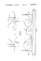
- FIG. 1 is an overall schematic view of the preferred embodiment of the apparatus of the present invention
- FIG. 2 is a sectional view taken along lines 2--2 of FIG. 1, illustrating in side view the sawing portion of the apparatus of the present invention
- FIG. 3 is a view taken along lines 3--3 of FIG. 1, illustrating a frontal view of the pair of saw assemblies with a work piece illustrated in phantom lines;
- FIGS 4 through 8a illustrate in sequential views the various cuts made by the saw assembly portion of the preferred embodiment of the apparatus of the present invention
- FIG. 9 illustrates the delivery system portion of the preferred embodiment of the apparatus, of the present invention for conveying a work piece between the cutting area and the drilling area;
- FIG. 10 illustrates in partial cut-away view a work piece secured in position for drilling in the apparatus of the present invention
- FIG. 11 illustrates in partial cut-away view an additional means of securing the work piece in the apparatus of the present invention
- FIG. 12 is a sectional view taken along lines 12--12 in FIG. 1, illustrating the drilling portion of the preferred embodiment of the apparatus of the present invention
- FIG. 13 illustrates the counter-sinking apparatus in the preferred embodiment of the apparatus and method of the present invention
- FIG. 14 illustrates a side view of the boring apparatus in the preferred embodiment of the apparatus and method of the present invention.
- FIG. 15 illustrates the assembling area of the preferred embodiment of the apparatus and method of the present invention
- FIG. 16a illustrates, along lines 16a--16a of FIG. 1, the bolting apparatus in the preferred embodiment of the apparatus and method of the present invention
- FIG. 16b illustrates along lines 16b--16b in FIG. 1, the front view of the bolting apparatus in the preferred embodiment of the apparatus and method of the present invention.
- FIGS. 1 through 16b The preferred embodiment of the apparatus and method of the present invention is best illustrated in FIGS. 1 through 16b, with the overall apparatus designated in FIG. 1 by Numeral 10.
- Apparatus 10 generally would comprise a pair of saw assemblies 30 and 32, with each of the saw assemblies comprising at least 4 saw blades designated by Numerals 31, 33, 35 and 37, as best illustrated in FIGS. 2 through 8, with each of the saw blades performing selected cuts on the ends of a wooden work piece 26.
- Work piece 26 would be delivered into saw assemblies 30 and 32 via feeder rollers 22 and 24 which are set in generally parallel relation to one another, for supporting the work piece as it is moved into position.
- Saw assemblies 30 and 32 would be located, in the preferred embodiment so that the ends of the work piece 26 would be fed through saw assemblies 30 and 32 on endless guide chain 34 and 36 during the operation of selectively cutting work piece 26.
- the details of the construction and sawing of work pieces 26 for eventual assemblage into barge fender units will be more fully discussed in subsequent FIGURES.
- FIG. 1 would also illustrate work piece 26 following its passage through saw assemblage 30 and 32 and being fed upon a second set of feeder rollers 42 and 44 as it comes off of the endless guide chains 34 and 36 following the cutting operation.
- Work piece 26 would then be fed into boring assembly 46 in which work piece 26 will be rigidly secured by pegs 48 (FIG. 10) to prevent side movement of work piece 26 as it is set upon boring assembly rollers 59 (FIG. 10,12) and also set secure by arms 49 through 51 holding work piece 26 secure during the boring process.
- arms 49 through 51 would be hydraulically operated for rigidly securing work piece 26 during the boring process.
- boring assembly which would include, in the preferred embodiment, at least 3 drills 52, 53 and 54, horizontally disposed, for simultaneously boring holes selectively spaced along the length of work piece 26.
- the drills 52 through 54 are preferably mounted for horizontal and vertical realignment depending on the length and width of the work piece to be bored.
- FIG. 1 in the preferred embodiment would be the step in the process subsequent to the boring process upon work piece 26.
- work piece 26 Following the boring process, work piece 26 would be moved on the assembly roller section 58 (FIG. 12) to the bolting area 60.
- feeder rollers 58 would be automatically powered so that work piece 26 could be easily delivered to bolting area 60.
- work piece 26 At bolting area 60, work piece 26 would be aligned, for bolting into a large fender unit 63.
- a single bolt would be mounted and hydraulically pushed through the assemblage of work pieces, the number to be predetermined and a nut adhered to the end of the bolt in the bolting process.
- FIGS. 2 and 3 as viewed on lines 2--2 and 3--3 of FIG. 1 respectively, illustrate the configuration of saw blades 31 through 37 in each saw assembly 30 and 32.
- Each saw assembly 30 and 32 would, in the preferred embodiment, comprise at least 4 saw blades, 31, 33, 35, and 37.
- the 4 blades would be disposed upon endless guide chains 34 and 36.
- Endless guide chains 34 and 36 are adapted with vertically extending upward arms 39 and 41, selectively spaced along the length of guide chains 34 and 36 for guiding a work piece 26 through the configuration of saws during the cutting process.
- saws 31 through 37 would perform identical cuts on each end of work piece 26 simultaneously during the cutting process.
- FIGS. 2 through 8a illustrate the type of cuts preferred on work piece 26 during the cutting process.
- First blade 31 would perform a cut through the cross section of work piece 26 (see wall portion 26a in FIG. 8a), thus, initially cutting the work piece at both ends to a clean and concise length along work piece 26.
- FIG. 3 illustrates in front view the cut made by each blade 31 through 37.
- a second blade 33 would then perform a 45° angle cut, in the preferred embodiment, the cut being approximately 6" from the end of the work piece 26 and approximately 1/3 into the width of work piece 26 (see wall portion 26f in FIG. 8a). The importance of this angle cut will be discussed further.
- Blade 35 would then perform a third cut as the work piece is delivered further through the assemblage of saws of 30 and 32, the third cut being a horizontally disposed cut through the end of work piece 26, approximately 1/3 to the midline of the width of the work piece 26, and to a depth equal to that point that the second cut was performed. (See front wall portion 26h in FIG. 8a).
- FIGS. 4 through 8 illustrates the sequential views of the cuts of the individual blades 33 through 37 as a work piece 26 moves through the saw assemblage 30 and 32.
- FIG. 8 illustrates one end of work piece 26, at it appears following the four cuts having been made by the four blades.
- FIG. 8a a section of barge fender 90 is seen in side view. After unit has been assembled, and set up upon the side wall of the barge, end portion 26a, would be held in place against the side of the barge by the use of angle iron or the like means, with side 26e being disposed against the barge wall. That portion of the barge fender defined by fender wall portions 26d, 26f and 26g, as seen in FIG. 8a, would be that portion of the fender that would bear the brunt of the barge striking an obstacle against the barge fender.
- Fender wall portion 26f as cut by saw 35 is angled at approximately 45°, since it has been found that when an object, such as a ship or other barge, strikes the barge fender work piece 26 at that point, if the wall portion 26f is cut off at a sharp 90° angle, then the fender would have a tendency to crack around that point and chip, often weakening the entire fender. With the 45° angle cut made by saw 35, the object would have a tendency to "slip" by and not produce as severe a shock to the fender as without the cut having been made. Subsequent FIGURES will illustrate the work piece 26 following the cutting of the end sections and the boring section 46 and bolt assembly section 60.
- FIGS. 9 through 12 illustrate work piece 26 in boring assembly area 46.
- work piece 26 is delivered out of saw assembly areas 30 and 32 by endless guide chains 34 and 36 onto a second set of parallel disposed feeder rollers 47 and 49.
- feeder rollers 47 and 49 as illustrated would be slightly tilted away from saw assemblance 30 and 32, so that the work piece 26, following the cutting process would be pulled by gravity onto boring section 46.
- FIG. 9 further illustrates the cooperation between feeder rollers 47 and 49 and boring assembly rollers 59.
- Work piece 26, would be delivered onto assembly froller 59, and proper positioned for boring of the holes.
- FIGS. 10 through 12 illustrate in detail the configuration of the boring assembly 46 as seen in partial views, in FIGS. 10 and 11, work piece 26 having been delivered upon boring roller assembly 59, peg 48 would be set in place to prevent work piece 26 from having any lateral movement during the boring process.
- Peg 48 would be connected to rollers 59 in the preferred embodiment with a chain or the like flexible means, so that while not in use, peg 52 would hang freely, yet be readily available for use.
- FIG. 11 illustrates 1 of 3 arms 54 which, in the preferred embodiment, would be hydraulically operated by a hydraulic system located in the area beneath rollers 59, and the arms (all three arms are viewed in FIG. 1) would simultaneously swing from a position away from the work piece 26 while the work piece is being placed in position for boring, and once hydraulically activated, one of two would swing to a position for rigidly securing work piece 26 against wall 57 during the boring process.
- FIG. 12 illustrates work piece 26 during the boring process.
- Drills 52, 53 and 54 (as seen in FIG. 1) are disposed on a track 58 which is parallel to boring assembly rollers 59, so that drills 52 through 54 are movable in a horizontal plane along the length of the work piece. Also, drills 52 through 54 would be adjustable on a vertical plane. The horizontal and vertical adjustment of the drills 52 through 54 is necessary since barge fender units come in various weights, widths and lengths, thus the positioning of the bores in the center of the work pieces along their lengths must be modified accordingly.
- each drill would have mounted thereupon, an elongated wood drill bit 62, horizontally disposed for simultaneously drilling three bores through the body of the work piece.
- the holes bored therethrough will be occupied by bolts when the work pieces 26 are bolted together into barge fender unit 63, as illustrated in FIG. 15.
- the work piece is then automatically delivered from the boring assembly area 46 to the bolting assembly area 60, along roller assembly 59 (see FIG. 1).
- the rollers 59 would be automatically activated for automatic movement of the work piece 26 along the rollers 59. This could be done by means of an electric or hydraulic motor, with a belt or the like means rotating the rollers for moving the work piece along the roller system. Such a system is known in the art.
- FIG. 13 illustrates a view of counter-sinking drill unit.
- the wooden fender once assembled be the only portion of the assembled fender which is exposed to striking by foreign objects.
- the work pieces on the ends of each section must be countersunk so that the head of the bolt 93 and the nut 92 are below or flush with the surface to prevent sheering off of the nut or the bolt head should the object strike the fender.
- the countersinking area 80 would be in that area between the boring area 46 and the bolting area 60, so that the selected work pieces, i.e. those which would be placed on the ends of each unit, may be counter-sunk as they move to the bolting area 60.
- FIGS. 15 and 16a illustrate the bolting assembly area of the individual work pieces 26 into a barge fender unit 63.
- arrow 81 illustrates the positioning of work pieces 26 as they arrived at the bolting area, along roller system 59.
- work piece 26 would be moved from roller system 59 to the assembly rack 94 by movable arms 96 and 98 which can be seen in the set position in in FIG. 1.
- Arms 96 and 98 would preferably be hydraulically operated and would move from a position beneath the roller system to a position above the rollers, thus lifting the work piece 26 off of rollers 59 and sliding the work piece 26 onto assembly rack 94.
- work piece 26 would have the ability to slide along the assembly 94 via rollers held on each unit of the assembly 94.
- assembly rack 94 preferably 10 work pieces per unit
- the work pieces are manually aligned so that holes 71 through 73 form a continuous bore throughout the work pieces 26 contained in the unit.
- the unbolted unit 63 is held in place with pegs 82 and 84 during the bolting process.
- FIG. 15 illustrates the apparatus involved in bolting.
- Apparatus 60 is seen with a pair of hydraulic arms 86 and 88 having I-beam section 90 disposed horizontally and rigidly attached by welding or bolting as seen in FIG. 15.
- Movable plates 100, 102 and 104 Mounted on horizontal I-beams 90 are movable plates 100, 102 and 104. Movable plates 100, 102 and 104, as better seen in FIGS. 16a and 16b, would be mounted on the flange of I-beam section 90, with an upper and lower lip section 106 and 108 for grasping around the flange of I-beam 90 for horizontal movement across I-beam 90.
- the plates 100, 102 and 104 would have the ability to slide along the flange 91 in order to adjust to the various widths of the various locations of the holes drilled into the work piece 26, depending on the length of the work piece involved.
- plates 100, 102 and 104 are adapted with three square raised projections 112, 114, and 116, which are disposed along the plates 100, 102 and 104 at three various heights.
- Each of the raised projections 112, 114 and 116 would receive the end of a socket 120.
- the socket 120 would be set upon projections 112, 114, 116 for holding the head 94 of bolt 93 during the bolting process.
Landscapes
- Life Sciences & Earth Sciences (AREA)
- Engineering & Computer Science (AREA)
- Wood Science & Technology (AREA)
- Forests & Forestry (AREA)
- Mechanical Engineering (AREA)
- Manufacturing & Machinery (AREA)
- Drilling And Boring (AREA)
Abstract
Description
Claims (17)
Priority Applications (1)
| Application Number | Priority Date | Filing Date | Title |
|---|---|---|---|
| US06/247,641 US4410024A (en) | 1981-03-25 | 1981-03-25 | Apparatus and method of assembling barge fenders |
Applications Claiming Priority (1)
| Application Number | Priority Date | Filing Date | Title |
|---|---|---|---|
| US06/247,641 US4410024A (en) | 1981-03-25 | 1981-03-25 | Apparatus and method of assembling barge fenders |
Publications (1)
| Publication Number | Publication Date |
|---|---|
| US4410024A true US4410024A (en) | 1983-10-18 |
Family
ID=22935707
Family Applications (1)
| Application Number | Title | Priority Date | Filing Date |
|---|---|---|---|
| US06/247,641 Expired - Lifetime US4410024A (en) | 1981-03-25 | 1981-03-25 | Apparatus and method of assembling barge fenders |
Country Status (1)
| Country | Link |
|---|---|
| US (1) | US4410024A (en) |
Cited By (7)
| Publication number | Priority date | Publication date | Assignee | Title |
|---|---|---|---|---|
| US5119855A (en) * | 1991-07-30 | 1992-06-09 | Norfield Industries | Face frame component machining system |
| US6745452B1 (en) * | 2003-04-07 | 2004-06-08 | Ronald Harrison | Apparatus for assembling temporary road mats |
| US20050022363A1 (en) * | 2003-04-07 | 2005-02-03 | Ronald Harrison | Three ply bolted temporary road mats and apparatus for manufacturing same |
| WO2006018608A1 (en) * | 2004-08-19 | 2006-02-23 | Eric Colbeck | Apparatus for constructing an assembly and use of the apparatus |
| US20090297266A1 (en) * | 2008-06-02 | 2009-12-03 | Strad Energy Services Ltd. | Connector and rig mat employing same |
| CN105945701A (en) * | 2016-05-20 | 2016-09-21 | 宿州市天缘家具有限责任公司 | Plate machining unit |
| CN107877149A (en) * | 2017-11-28 | 2018-04-06 | 醴陵市绿源商贸有限公司 | A kind of material allocation case basket pallet and material allocation method and assemble method |
Citations (6)
| Publication number | Priority date | Publication date | Assignee | Title |
|---|---|---|---|---|
| US2789598A (en) * | 1953-09-14 | 1957-04-23 | George C Berger | Machine for fabricating pieces of lumber |
| US3331410A (en) * | 1965-03-05 | 1967-07-18 | Clary Corp | Woodworking machine |
| US3473583A (en) * | 1966-08-27 | 1969-10-21 | Pallagrosi S N C Flli | Machine for squaring plates or panels in combination with a multiple drillof wood,plastic material or the like,ing machine |
| US3543374A (en) * | 1968-06-17 | 1970-12-01 | John R Mcconnell | Drilling and bolting of structural members |
| US3546772A (en) * | 1968-06-17 | 1970-12-15 | John R Mcconnell | Structural member fabricating process |
| US4221246A (en) * | 1978-08-03 | 1980-09-09 | Grutter William G | Floor joist machine |
-
1981
- 1981-03-25 US US06/247,641 patent/US4410024A/en not_active Expired - Lifetime
Patent Citations (6)
| Publication number | Priority date | Publication date | Assignee | Title |
|---|---|---|---|---|
| US2789598A (en) * | 1953-09-14 | 1957-04-23 | George C Berger | Machine for fabricating pieces of lumber |
| US3331410A (en) * | 1965-03-05 | 1967-07-18 | Clary Corp | Woodworking machine |
| US3473583A (en) * | 1966-08-27 | 1969-10-21 | Pallagrosi S N C Flli | Machine for squaring plates or panels in combination with a multiple drillof wood,plastic material or the like,ing machine |
| US3543374A (en) * | 1968-06-17 | 1970-12-01 | John R Mcconnell | Drilling and bolting of structural members |
| US3546772A (en) * | 1968-06-17 | 1970-12-15 | John R Mcconnell | Structural member fabricating process |
| US4221246A (en) * | 1978-08-03 | 1980-09-09 | Grutter William G | Floor joist machine |
Cited By (13)
| Publication number | Priority date | Publication date | Assignee | Title |
|---|---|---|---|---|
| US5119855A (en) * | 1991-07-30 | 1992-06-09 | Norfield Industries | Face frame component machining system |
| US7210211B2 (en) * | 2003-04-07 | 2007-05-01 | Ronald Harrison | Three ply bolted temporary road mats and apparatus for manufacturing same |
| US6745452B1 (en) * | 2003-04-07 | 2004-06-08 | Ronald Harrison | Apparatus for assembling temporary road mats |
| US20050022363A1 (en) * | 2003-04-07 | 2005-02-03 | Ronald Harrison | Three ply bolted temporary road mats and apparatus for manufacturing same |
| US20080193213A1 (en) * | 2003-04-07 | 2008-08-14 | Ronald Harrison | Three ply bolted temporary road mats and apparatus for manufacturing same |
| WO2006018608A1 (en) * | 2004-08-19 | 2006-02-23 | Eric Colbeck | Apparatus for constructing an assembly and use of the apparatus |
| GB2431056A (en) * | 2004-08-19 | 2007-04-11 | Eric Colbeck | Apparatus for constructing an assembly and use of the apparatus |
| GB2431056B (en) * | 2004-08-19 | 2008-10-08 | Eric Colbeck | Apparatus for constructing an assembly and use of the apparatus |
| US20090297266A1 (en) * | 2008-06-02 | 2009-12-03 | Strad Energy Services Ltd. | Connector and rig mat employing same |
| US8096728B2 (en) | 2008-06-02 | 2012-01-17 | Strad Energy Services, Ltd. | Connector and rig mat employing same |
| CN105945701A (en) * | 2016-05-20 | 2016-09-21 | 宿州市天缘家具有限责任公司 | Plate machining unit |
| CN105945701B (en) * | 2016-05-20 | 2018-03-02 | 宿州市天缘家具有限责任公司 | A kind of sheet fabrication unit |
| CN107877149A (en) * | 2017-11-28 | 2018-04-06 | 醴陵市绿源商贸有限公司 | A kind of material allocation case basket pallet and material allocation method and assemble method |
Similar Documents
| Publication | Publication Date | Title |
|---|---|---|
| EP1405693B1 (en) | machining apparatus for working wooden workpieces | |
| DE102007020445B4 (en) | Automated system for the precise cutting of short lumber pieces | |
| US3965788A (en) | Lumber making attachment | |
| EP3967466A1 (en) | Plate partitioning facility for partitioning plate-shaped workpieces and method for its operation | |
| US4410024A (en) | Apparatus and method of assembling barge fenders | |
| US4204624A (en) | Nailing machine for use in the manufacture of wooden pallets | |
| US4570687A (en) | Method and apparatus for producing lumber products which are machined on all sides | |
| US6708593B1 (en) | Folding, straight-line, workpiece guide for a band saw | |
| US20010034930A1 (en) | Apparatus and process for boring and bolting pallets | |
| US3687269A (en) | Apparatus for edging and resawing lumber | |
| DE102021125391B4 (en) | Destacking device and wood processing plant with such a destacking device | |
| JPH0526617B2 (en) | ||
| EP0571754B1 (en) | Transporting device for a beam longitudinally displacable | |
| US5253685A (en) | Clamping and feeding device for the machining of boles | |
| DE69010190T2 (en) | Wooden block turning device. | |
| DE19905876A1 (en) | Woodworking system in portal construction | |
| WO2000010760A1 (en) | Elongate body processing | |
| DE3511272C2 (en) | ||
| CA2277562A1 (en) | Method and apparatus for forming eight or more sided timbers | |
| EP0698456B1 (en) | Transporting device for a longitudinally displacable beam | |
| JPH0155963B2 (en) | ||
| US4463786A (en) | Timber dapping apparatus | |
| JPH0820006A (en) | Precutting device | |
| DE2802737C3 (en) | Device for introducing a final route extension consisting of extension frames | |
| DE3226123C2 (en) |
Legal Events
| Date | Code | Title | Description |
|---|---|---|---|
| STCF | Information on status: patent grant |
Free format text: PATENTED CASE |
|
| PS | Patent suit(s) filed | ||
| MAFP | Maintenance fee payment |
Free format text: PAYMENT OF MAINTENANCE FEE, 4TH YEAR, PL 96-517 (ORIGINAL EVENT CODE: M170); ENTITY STATUS OF PATENT OWNER: SMALL ENTITY Year of fee payment: 4 |
|
| MAFP | Maintenance fee payment |
Free format text: PAYMENT OF MAINTENANCE FEE, 4TH YEAR, PL 96-517 (ORIGINAL EVENT CODE: M170); ENTITY STATUS OF PATENT OWNER: SMALL ENTITY Year of fee payment: 4 |
|
| FEPP | Fee payment procedure |
Free format text: MAINTENANCE FEE REMINDER MAILED (ORIGINAL EVENT CODE: REM.); ENTITY STATUS OF PATENT OWNER: SMALL ENTITY |
|
| FEPP | Fee payment procedure |
Free format text: SURCHARGE FOR LATE PAYMENT, PL 96-517 (ORIGINAL EVENT CODE: M176); ENTITY STATUS OF PATENT OWNER: SMALL ENTITY |
|
| MAFP | Maintenance fee payment |
Free format text: PAYMENT OF MAINTENANCE FEE, 8TH YEAR, PL 96-517 (ORIGINAL EVENT CODE: M171); ENTITY STATUS OF PATENT OWNER: SMALL ENTITY Year of fee payment: 8 |
|
| FEPP | Fee payment procedure |
Free format text: PAYOR NUMBER ASSIGNED (ORIGINAL EVENT CODE: ASPN); ENTITY STATUS OF PATENT OWNER: SMALL ENTITY |
|
| MAFP | Maintenance fee payment |
Free format text: PAYMENT OF MAINTENANCE FEE, 12TH YR, SMALL ENTITY (ORIGINAL EVENT CODE: M285); ENTITY STATUS OF PATENT OWNER: SMALL ENTITY Year of fee payment: 12 |
|
| FEPP | Fee payment procedure |
Free format text: PAYER NUMBER DE-ASSIGNED (ORIGINAL EVENT CODE: RMPN); ENTITY STATUS OF PATENT OWNER: SMALL ENTITY |