US4409511A - Phase transition cooled window for broad beam electron gun - Google Patents
Phase transition cooled window for broad beam electron gun Download PDFInfo
- Publication number
- US4409511A US4409511A US06/236,808 US23680881A US4409511A US 4409511 A US4409511 A US 4409511A US 23680881 A US23680881 A US 23680881A US 4409511 A US4409511 A US 4409511A
- Authority
- US
- United States
- Prior art keywords
- window
- coolant
- liquid
- atomized
- cooling
- Prior art date
- Legal status (The legal status is an assumption and is not a legal conclusion. Google has not performed a legal analysis and makes no representation as to the accuracy of the status listed.)
- Expired - Lifetime
Links
- 230000007704 transition Effects 0.000 title description 11
- 239000002826 coolant Substances 0.000 claims abstract description 151
- 239000007788 liquid Substances 0.000 claims abstract description 109
- 238000001816 cooling Methods 0.000 claims abstract description 56
- 239000002245 particle Substances 0.000 claims abstract description 53
- 238000000034 method Methods 0.000 claims abstract description 12
- 239000000463 material Substances 0.000 claims description 107
- XLYOFNOQVPJJNP-UHFFFAOYSA-N water Substances O XLYOFNOQVPJJNP-UHFFFAOYSA-N 0.000 claims description 20
- LYCAIKOWRPUZTN-UHFFFAOYSA-N Ethylene glycol Chemical compound OCCO LYCAIKOWRPUZTN-UHFFFAOYSA-N 0.000 claims description 18
- 230000008859 change Effects 0.000 claims description 18
- 238000009834 vaporization Methods 0.000 claims description 10
- 230000008016 vaporization Effects 0.000 claims description 10
- 238000000151 deposition Methods 0.000 claims description 8
- 238000002156 mixing Methods 0.000 claims description 6
- 239000000203 mixture Substances 0.000 claims description 5
- 230000001105 regulatory effect Effects 0.000 claims description 5
- 239000000725 suspension Substances 0.000 claims description 4
- 239000000443 aerosol Substances 0.000 claims description 2
- 238000009835 boiling Methods 0.000 abstract description 5
- 239000007791 liquid phase Substances 0.000 abstract description 2
- 239000007792 gaseous phase Substances 0.000 abstract 1
- 239000010408 film Substances 0.000 description 16
- 239000012071 phase Substances 0.000 description 16
- 239000007789 gas Substances 0.000 description 13
- 238000010894 electron beam technology Methods 0.000 description 11
- 238000010521 absorption reaction Methods 0.000 description 3
- 230000006872 improvement Effects 0.000 description 3
- 230000014509 gene expression Effects 0.000 description 2
- 230000017525 heat dissipation Effects 0.000 description 2
- 239000002184 metal Substances 0.000 description 2
- 229910052751 metal Inorganic materials 0.000 description 2
- 230000000737 periodic effect Effects 0.000 description 2
- 230000001133 acceleration Effects 0.000 description 1
- 238000000889 atomisation Methods 0.000 description 1
- 230000004888 barrier function Effects 0.000 description 1
- 238000010276 construction Methods 0.000 description 1
- 230000007850 degeneration Effects 0.000 description 1
- 230000008021 deposition Effects 0.000 description 1
- 238000005421 electrostatic potential Methods 0.000 description 1
- 239000011888 foil Substances 0.000 description 1
- 238000002347 injection Methods 0.000 description 1
- 239000007924 injection Substances 0.000 description 1
- 230000003993 interaction Effects 0.000 description 1
- 238000002955 isolation Methods 0.000 description 1
- 239000012528 membrane Substances 0.000 description 1
- 150000002739 metals Chemical class 0.000 description 1
- 230000004048 modification Effects 0.000 description 1
- 238000012986 modification Methods 0.000 description 1
- 239000004033 plastic Substances 0.000 description 1
- 239000002985 plastic film Substances 0.000 description 1
- 229920006255 plastic film Polymers 0.000 description 1
- 230000008569 process Effects 0.000 description 1
- 230000005855 radiation Effects 0.000 description 1
- 239000007921 spray Substances 0.000 description 1
- 239000013077 target material Substances 0.000 description 1
- 239000010409 thin film Substances 0.000 description 1
- 239000012808 vapor phase Substances 0.000 description 1
Images


Classifications
-
- H—ELECTRICITY
- H05—ELECTRIC TECHNIQUES NOT OTHERWISE PROVIDED FOR
- H05H—PLASMA TECHNIQUE; PRODUCTION OF ACCELERATED ELECTRICALLY-CHARGED PARTICLES OR OF NEUTRONS; PRODUCTION OR ACCELERATION OF NEUTRAL MOLECULAR OR ATOMIC BEAMS
- H05H7/00—Details of devices of the types covered by groups H05H9/00, H05H11/00, H05H13/00
-
- H—ELECTRICITY
- H01—ELECTRIC ELEMENTS
- H01J—ELECTRIC DISCHARGE TUBES OR DISCHARGE LAMPS
- H01J5/00—Details relating to vessels or to leading-in conductors common to two or more basic types of discharge tubes or lamps
- H01J5/02—Vessels; Containers; Shields associated therewith; Vacuum locks
- H01J5/18—Windows permeable to X-rays, gamma-rays, or particles
Definitions
- This invention relates generally to the cooling of charged-particle-transparent windows used in charged particle accelerator systems and, in particular, to a phase transition cooled window for broad beam electron guns.
- a charged particle accelerator system requires that the particle-emitting cathode be housed in a vacuum-tight housing.
- a particle-attracting anode which is transparent to such particles while impervious to gas.
- the vacuum within the housing is thereby maintained while permitting the accelerated particles to be emitted from the accelerator.
- the particles emitted from the cathode are attracted and accelerated toward the anode, and upon reaching the anode, pass through the particle-transparent anode window to the exterior of the accelerator.
- a window which is perfectly transparent to such particles is not realizable. Therefore, the passage of the particles through the window results in some interaction by the particles with the window material. This results in the generation of heat.
- particle beam intensities are very high, the heat generated in transparent windows is also very high, leading to possible degeneration of the window material. It is, therefore, desirable to devise some means for cooling these transparent windows.
- Desirable characteristics of any cooling means include minimal interference by the cooling apparatus with the particle beam, as well as capacity to remove large quantities of heat.
- the low mass density of the gases satisfies the non-interference requirement above.
- the amount of heat which can be carried away by a gas cooling system is small.
- the present invention uses a phase transition system wherein heat is principally consumed locally when the coolant material changes state from a liquid to a gas. The temperature at which this state change occurs corresponds to the boiling point of the material.
- the heat of vaporization of the coolant mass is equal to the amount of heat which can be absorbed by the coolant mass during the liquid-to-vapor phase change without a rise in temperature of the material.
- phase transition cooling technique provides substantial improvement in heat dissipation capacity for a given quantity of coolant material.
- the specific heat of water (the ratio of the amount of heat, in calories, required to raise one gram of water one degree C. In temperature) is 1.0.
- the heat of vaporization of water is 540 calories per gram. Therefore, while in a conduction cooling system a gram of water can carry away one calorie of heat with a one degree C. rise in temperature, in a phase change system the same gram of water can absorb 540 calories of heat with no increase in temperature.
- the non-phase change liquid-cooling apparatuses in the prior art are not practicable for use in broad beam particle accelerators.
- a coolant flow chamber is necessary to maintain the coolant material in contact with the window.
- the flow chamber depth must, therefore, be kept small, for example, on the order of several hundred micrometers. It is very difficult to maintain a spacing of this order over a large surface area, as is typically present in broad beam electron gun windows.
- larger quantities of liquid coolant are required to dissipate the generated heat, hence the corresponding large areal mass densities of such quantities interfere with and dissipate the electron beam.
- Coolant material is selected according to the temperature at which the window is desired to be operated. Control requirements over liquid flow rates are significantly reduced.
- the atomization of the coolant material not only enhances the phase change process, it also reduces the areal mass of the coolant material significantly.
- non-phase-change cooling at an electron beam power density level of 10 watts per second and a coolant velocity of 300 feet per second, results in a coolant-temperature rise of 80 degrees Centigrade and requires a water flow rate of 1.1 cm 3 /sec.
- phase change cooling requires a water flow rate of only 0.16 cm 3 /sec. and results in no coolant-temperature rise.
- the charged particle transparent window is heated only during each burst.
- Another embodiment of the present invention includes means for supplying a vaporizable, coolant liquid, and means for depositing the liquid on the window to form a film of the coolant liquid on the window. During each burst of charged particle emissions, the film absorbs heat from the window and at least some of the film changes from a liquid to a gaseous state.
- FIG. 1 is a simplified, longitudinal, cross-sectional view of the present invention operatively positioned between a broad beam electron gun and a target.
- FIG. 2 is a perspective view of the cooling chamber, with the second transparent window not shown, of one embodiment of the present invention.
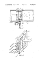
- FIG. 3 is a section view of one embodiment of the atomizer means of the present invention taken generally along the lines 3--3 in FIG. 2.
- FIG. 4 is a graph of typical heat absorption characteristics of the phase-transition cooling system for various coolant mass flow rates.
- FIG. 5 is a simplified illustration of one window configuration of the present invention.
- FIG. 6 is a simplified illustration of an alternative window configuration of the present invention for medium pressure coolant chamber application.
- FIG. 7 is a simplified illustration of another alternative window configuration of the present invention for use with high pressure flow in the coolant chamber.
- FIG. 8 is a simplified illustration of still another alternative window configuration of the present invention for use with medium pressure flows in the coolant chamber.
- FIG. 1 the functional relationship of the phase transition cooled window in a broad beam electron gun is shown.
- An electron beam indicated by an arrow 10
- the beam 10 is electrostatically attracted to an electron-transparent anode window 16, through which it passes, thence into a coolant chamber 18, through a second electron transparent window 20, and then onto a target 22.
- This target 22 can be an object at normal atmospheric pressure, at several times the normal atmospheric pressure, or at less than normal atmospheric pressure.
- the preferred embodiment of the invention includes a housing 24 having the coolant chamber 18, an atomizer 26, a pipe 28 for supplying the liquid to be atomized from an external source (not shown), and propelling means 30, such as a pipe connection to an external source, not shown, of compressed gas, for directing the atomized liquid onto the window 16 to be cooled.
- a second electron transparent window 20 is provided when the target 22 is at a pressure different from the pressure of the coolant chamber 18 or when isolation between the target and the coolant material is required.
- This second window 20 must also be cooled.
- the second electron transparent window 20 can also be used to form, in conjunction with the housing 24 and the electron transparent anode window 16, the chamber 18 which serves to guide the atomized liquid over the windows 16 and 20. Where lengthy windows are sought to be cooled, the above chamber 18 simplifies the required propelling means 30. In such case, the atomized material is introduced at one end of the chamber 18 at a specific flow rate with the configuration of the chamber 18 directing the flow over the window surfaces to be cooled.
- an inlet passageway 32 to permit injection of the atomized liquid into the coolant chamber 18, and an exhaust passageway 34, disposed opposite to the inlet passageway 32, to permit an escape of the state-changed coolant material.
- the second transparent window 20 may not be required.
- the coolant chamber housing 24 and/or propelling means 30 should be modified so that the aerosol mixture will be directed uniformly onto the surface of the first electron transparent window 16, without the use of a closed guiding passageway as would be provided by the second transparent window 20.
- Transparent windows 16 and 20 are shown in FIG. 1 in exaggerated scale for ease of illustration. In practice, the windows 16 and 20 should be made as thin as possible, consistent with the pressure differentials which exist between the coolant chamber and the electron gun vacuum chamber 12, and the target matter 22.
- Window material includes a metallic membrane or a plastic film pressure barrier. The choice between metal and plastic is made n the basis of strength, local heat condition, energy deposition and susceptibility of the foil to fatigue and radiation damage.
- FIG. 2 is a perspective view of the coolant chamber housing 24, with the second transparent window 20 removed.
- FIG. 3 is a section view of the atomizer section 26 taken generally along the lines 3--3 in FIG. 2.
- the coolant chamber housing 24 has a chamber shaped to conform to the shape of the electron transparent anode window 16.
- the window can be round, oblong, rectangular, annular, or any of a variety of shapes. In the preferred embodiment the window is rectangular in shape, approximately 5 cm in width and 50 cm in length.
- the housing 24 overlays the anode window 16 so as to leave the entire electron transparent portion of the window 16 unobstructed.
- the atomizer unit 26 is secured to the coolant housing 24 so that atomized liquid emerging from the atomizer structure 26 enters the atomized liquid inlet passageway 32 and thence is directed into the coolant chamber 18.
- the direction of coolant flow is indicated by arrows 38.
- pneumatic nozzles 36 for atomizing the coolant material are shown.
- Coolant material such as water
- a gas flow such as air, from an external source of compressed air, is supplied to the nozzles 36, by suitable means, such as conduits 30.
- the nozzles 36 mix the air and water to form a suspension of water droplets in the air flow. The mixture is then emitted from the nozzles 36.
- the nozzles 36 can be selected to provide a number of different spray patterns to provide the required directivity for the various possible shapes and configurations of the transparent window.
- Pneumatic nozzles can be used to atomize the coolant liquid by mixing a gas, which has been accelerated to a high velocity relative to the liquid, with the liquid; the velocity differential thus causing the liquid to be subdivided into fine droplets by the acceleration of the gas through the liquid.
- atomizing means include sonic nozzles wherein the coolant liquid is caused to flow over a vibrating surface. The frequency of the vibration determines the size of the droplets produced. As described above, the atomized coolant liquid is then mixed with the air to form a suspension of water droplets in the air flow. The mixture is then emitted from the nozzles 36.
- the droplet size produced by the atomizing means 26 should be small with respect to the accelerated electron range.
- the electron range is determined by the magnitude of the electrostatic potential used to accelerate the electrons and the areal mass density of the material through which they must pass. The greater the areal mass density, or the lower the accelerating potential, the lower the electron range.
- the electron range in water is on the order of a few hundred micrometers, hence a atomized water droplet size of 30 to 50 micrometers is preferred.
- the pneumatic nozzles disclosed in FIG. 3 can be substituted for by sonic nozzles (hereinafter also designated as 36).
- sonic nozzles hereinafter also designated as 36.
- air flow containing the atomized coolant liquid is directed onto the anode window 16 in a hypothetical plane parallel to the anode window 16.
- the atomized liquid comes into contact with the hot surface of the anode window 16, it absorbs sufficient heat from the anode window 16 to vaporize.
- the amount of atomized coolant which changes state is determined by the atomized liquid content of the air flow, the rate of flow of the atomized liquid across the window to be cooled, and the heat content of the window to be cooled.
- stable temperature operation can be obtained when the anode window is run at a power density corresponding to 155 watts per square centimeter when 37% of the atomized liquid flowing across the anode window changes state.
- Typical improvements in efficiency due to the use of phase change cooling include, for example, an 80 fold improvement in cooling capacity from 1.5 watts per square centimeter, when only air is used as a cooling material, to 123 watts per centimeter, when atomized water is used as the cooling material.
- the particular coolant material used is chosen according to the temperature at which the anode window is sought to be operated and the power density of the electron beam used. For example, an operating temperature of approximately 100 degrees centigrade can be maintained, at atmospheric pressure, at an operating power density of 77 watts per square centimeter when water is used as a coolant material. On the other hand, an operating temperature of approximately 200 degrees centigrade can be maintained, at atmospheric pressure, at a power density level of 50 watts per square centimeter when ethylene glycol is used as the coolant material. At different operating pressures the operating temperature will correspond to the temperature of vaporization of the particular material at the particular pressure.
- the amount of coolant material which must come into contact with the anode window differs from material to material. For example, since ethylene glycol has a heat of vaporization almost one-third that of water, more ethylene glycol is necessary to cool a particular operating power density than when water is used as the coolant material.
- FIG. 4 illustrates the increase in heat absorbing capacity of the atomized coolant liquid when different mass flow rates are used.
- mass flow rates the higher the mass flow rates the greater the degree of interference of the coolant material with the electron beam.
- stable, high temperature operation of the window for example at 200 degrees centigrade, which is not realizable when water is used as a coolant under normal conditions, can be obtained through the use of ethylene glycol (boiling point of approximately 200 degrees C.) as the coolant material.
- stable, low temperature operation can be realized using materials having low temperature boiling points. Again, the heat dissipation capacity of a particular material at its boiling point is a function of its heat of vaporization.
- the exhaust passageway 34 is unrestricted.
- the structure of the coolant chamber 18, and the exhaust passageway 34 can be modified to accommodate the various operating conditions of the electron gun 14 and the target 22.
- the exhaust passageway 34 can be modified to restrict the flow of coolant material being exhausted. This, in turn, increases the pressure within the coolant chamber 18, thereby countering the pressure applied to the second transparent window 20 by the higher pressure target atmosphere 22. Additionally, by increasing the pressure within the chamber 18 the temperature of vaporization, hence the operating temperature of the window can be controlled.
- FIG. 5 illustrates the use of supporting rods 40 on the vacuum-side of the anode window 16.
- thinner windows can be used while maintaining the required electron gun vacuum, with negligible interference with the electron beam itself.
- electron beam shields 48 are disposed between the rods 40 and the electron beam 10 to deflect the beam away from the rods.
- the shields are typically not one hundred percent effective; therefore, conventional liquid cooling of the rods 40 (circulation of liquid through the interior of the rods) is used.
- the second transparent window 20 is shown unsupported in FIG. 5.
- supporting ribs for the second transparent window can be used.
- FIG. 6 illustrates the use of planar ribs or webs 42 disposed in a hypothetical plane perpendicular to the transparent windows 16 and 20 and parallel to the direction of flow of the cooling medium which provide support to the second transparent window 20 when there is medium pressure (1-3 atmospheres) in the coolant chamber 18 and 3 atmospheres of pressure at the target 22.
- medium pressure 1-3 atmospheres
- FIG. 8 shows the use of rod shaped ribs 46 on the side of the second transparent window 20 which is closest to the electron gun 14 when the pressure in the coolant chamber 18 is less than the target chamber 22 to support the second transparent window 20.
- the method of phase transition cooling of particle transparent windows in particle accelerators comprises the steps of atomizing a coolant material having a liquid state, and then directing the atomized material onto the window to be cooled so that the atomized material absorbs heat from the window and, at least, some of the material changes from a liquid to a gaseous state.
- the amount of heat generated within the window material depends upon the particle beam intensity, or energy level.
- the heat generated is also a function of the duration of the charged particle bursts. Therefore, for a given beam energy level and a given burst duration, a corresponding quantity of heat will be generated in the charged particle transparent window.
- the amounts of heat which can be dissipated by the film of coolant liquid which is deposited on the charged particle transparent window surface is a function of the amount of liquid present. If the thickness of the film is large, for example, greater than several hundred micrometers, the problems of limited electron range present when a non-atomized mass of liquid coolant is used, will arise. On the other hand, for very thin films of liquid coolant, the corresponding heat capacity of such film is small. However, the problem of excessive interference with electron beam is eliminated.
- the beam energy levels of 200 KeV to 500 KeV, burst durations of less than two microseconds, and time periods of approximately 10 milliseconds between each burst a film of coolant liquid having a thickness of the order of a few tens of micrometers will be sufficient to dissipate all of the heat generated in the window by each burst.
- the present invention has an embodiment similar to that of the window cooling apparatus just described for the continuous mode operation of a charged-particle accelerator system.
- the coolant liquid supply means need not supply coolant liquid to the atomizer section 26 on a continuous basis.
- the supply means should, instead, be regulated so that atomized material is injected into the coolant chamber 18 during the time period when no electron emission is occurring.
- the regulated supply means can take the form of pump which is operated in synchronization with the pulsing of the charged-particle accelerator system.
- the operation of the charged particle transparent window coolant apparatus will be identical to that when the accelerator 14 is operated in a continuous mode.
- the method of phase transition cooling of particle transparent windows in particle accelerators when the particle accelerators are operated in a pulsed mode, and wherein the window is heated during the duration of each pulse of charged particles comprises the steps of supplying a vaporizable, liquid cooling material; and depositing the cooling material on the surface of the window to be cooled to form a film of the liquid coolant, so that during the time period when charged particles are being emitted through the window, the film absorbs heat from the window and at least some of the coolant material changes from a liquid to a gaseous state.
Landscapes
- Physics & Mathematics (AREA)
- Engineering & Computer Science (AREA)
- Plasma & Fusion (AREA)
- Spectroscopy & Molecular Physics (AREA)
Abstract
Description
Claims (27)
Priority Applications (1)
| Application Number | Priority Date | Filing Date | Title |
|---|---|---|---|
| US06/236,808 US4409511A (en) | 1981-02-23 | 1981-02-23 | Phase transition cooled window for broad beam electron gun |
Applications Claiming Priority (1)
| Application Number | Priority Date | Filing Date | Title |
|---|---|---|---|
| US06/236,808 US4409511A (en) | 1981-02-23 | 1981-02-23 | Phase transition cooled window for broad beam electron gun |
Publications (1)
| Publication Number | Publication Date |
|---|---|
| US4409511A true US4409511A (en) | 1983-10-11 |
Family
ID=22891056
Family Applications (1)
| Application Number | Title | Priority Date | Filing Date |
|---|---|---|---|
| US06/236,808 Expired - Lifetime US4409511A (en) | 1981-02-23 | 1981-02-23 | Phase transition cooled window for broad beam electron gun |
Country Status (1)
| Country | Link |
|---|---|
| US (1) | US4409511A (en) |
Cited By (19)
| Publication number | Priority date | Publication date | Assignee | Title |
|---|---|---|---|---|
| US4550684A (en) * | 1983-08-11 | 1985-11-05 | Genus, Inc. | Cooled optical window for semiconductor wafer heating |
| EP0196699A1 (en) * | 1985-03-20 | 1986-10-08 | Philips Patentverwaltung GmbH | Projection cathode ray tube |
| US4680447A (en) * | 1983-08-11 | 1987-07-14 | Genus, Inc. | Cooled optical window for semiconductor wafer heating |
| EP0651398A1 (en) * | 1993-10-26 | 1995-05-03 | W.R. Grace & Co. | Hydronic cooling of particle accelerator window |
| US5486703A (en) * | 1992-10-01 | 1996-01-23 | W. R. Grace & Co.-Conn. | Hydronic cooling of particle accelerator window |
| US5530255A (en) * | 1990-08-17 | 1996-06-25 | Raychem Corporation | Apparatus and methods for electron beam irradiation |
| DE19518623A1 (en) * | 1995-05-24 | 1996-11-28 | Messer Griesheim Schweistechni | Surface electron irradiation device for electron hardening of stiff or flexible materials in printing |
| US5612588A (en) * | 1993-05-26 | 1997-03-18 | American International Technologies, Inc. | Electron beam device with single crystal window and expansion-matched anode |
| US5898261A (en) * | 1996-01-31 | 1999-04-27 | The United States Of America As Represented By The Secretary Of The Air Force | Fluid-cooled particle-beam transmission window |
| AU708665B2 (en) * | 1992-10-01 | 1999-08-12 | Cryovac, Inc. | Hydronic cooling of particle accelerator window |
| WO1999048344A1 (en) * | 1998-03-13 | 1999-09-23 | Forschungszentrum Karlsruhe Gmbh | Gas target window |
| US6210516B1 (en) | 1994-02-18 | 2001-04-03 | Ronald Sinclair Nohr | Process of enhanced chemical bonding by electron seam radiation |
| US20020113534A1 (en) * | 2000-12-14 | 2002-08-22 | Fujitsu Limited | Backlight having discharge tube, reflector and heat conduction member contacting discharge tube |
| US6530539B2 (en) * | 2001-02-09 | 2003-03-11 | Raytheon Company | Internal fluid cooled window assembly |
| US6559424B2 (en) | 2001-01-02 | 2003-05-06 | Mattson Technology, Inc. | Windows used in thermal processing chambers |
| US6614037B2 (en) * | 2000-02-07 | 2003-09-02 | Ebara Corporation | Electron beam irradiating apparatus |
| US20110012495A1 (en) * | 2009-07-20 | 2011-01-20 | Advanced Electron Beams, Inc. | Emitter Exit Window |
| US20160258057A1 (en) * | 2015-03-06 | 2016-09-08 | Lam Research Corporation | Clean resistant windows for ultraviolet thermal processing |
| EP4279403A3 (en) * | 2022-04-26 | 2024-04-03 | Tetra Laval Holdings & Finance S.A. | Sterilization apparatus having an irradiation beam emitting device and packaging machine having a sterilization apparatus |
Citations (5)
| Publication number | Priority date | Publication date | Assignee | Title |
|---|---|---|---|---|
| US2856532A (en) * | 1955-06-16 | 1958-10-14 | Eugene F Martina | Pulsed ion source |
| US2898492A (en) * | 1955-12-13 | 1959-08-04 | Gen Electric | Apparatus for and method of cooling beam transmitting windows |
| US3105916A (en) * | 1960-09-08 | 1963-10-01 | High Voltage Engineering Corp | Radiation beam window |
| US3306350A (en) * | 1962-05-22 | 1967-02-28 | Thomson Houston Comp Francaise | Electron discharge tube having improved cooling means therefor |
| US4141224A (en) * | 1976-03-31 | 1979-02-27 | The United States Of America As Represented By The Administrator Of The National Aeronautics And Space Administration | Closed loop spray cooling apparatus |
-
1981
- 1981-02-23 US US06/236,808 patent/US4409511A/en not_active Expired - Lifetime
Patent Citations (5)
| Publication number | Priority date | Publication date | Assignee | Title |
|---|---|---|---|---|
| US2856532A (en) * | 1955-06-16 | 1958-10-14 | Eugene F Martina | Pulsed ion source |
| US2898492A (en) * | 1955-12-13 | 1959-08-04 | Gen Electric | Apparatus for and method of cooling beam transmitting windows |
| US3105916A (en) * | 1960-09-08 | 1963-10-01 | High Voltage Engineering Corp | Radiation beam window |
| US3306350A (en) * | 1962-05-22 | 1967-02-28 | Thomson Houston Comp Francaise | Electron discharge tube having improved cooling means therefor |
| US4141224A (en) * | 1976-03-31 | 1979-02-27 | The United States Of America As Represented By The Administrator Of The National Aeronautics And Space Administration | Closed loop spray cooling apparatus |
Cited By (33)
| Publication number | Priority date | Publication date | Assignee | Title |
|---|---|---|---|---|
| US4680447A (en) * | 1983-08-11 | 1987-07-14 | Genus, Inc. | Cooled optical window for semiconductor wafer heating |
| US4550684A (en) * | 1983-08-11 | 1985-11-05 | Genus, Inc. | Cooled optical window for semiconductor wafer heating |
| EP0196699A1 (en) * | 1985-03-20 | 1986-10-08 | Philips Patentverwaltung GmbH | Projection cathode ray tube |
| US5530255A (en) * | 1990-08-17 | 1996-06-25 | Raychem Corporation | Apparatus and methods for electron beam irradiation |
| US5486703A (en) * | 1992-10-01 | 1996-01-23 | W. R. Grace & Co.-Conn. | Hydronic cooling of particle accelerator window |
| AU708665B2 (en) * | 1992-10-01 | 1999-08-12 | Cryovac, Inc. | Hydronic cooling of particle accelerator window |
| US5612588A (en) * | 1993-05-26 | 1997-03-18 | American International Technologies, Inc. | Electron beam device with single crystal window and expansion-matched anode |
| EP0651398A1 (en) * | 1993-10-26 | 1995-05-03 | W.R. Grace & Co. | Hydronic cooling of particle accelerator window |
| US6210516B1 (en) | 1994-02-18 | 2001-04-03 | Ronald Sinclair Nohr | Process of enhanced chemical bonding by electron seam radiation |
| EP0871972A4 (en) * | 1995-01-05 | 2000-03-01 | American Int Tech | ELECTRON BEAM DEVICE WITH SINGLE CRYSTAL WINDOW AND ADAPTED ANODE |
| DE19518623A1 (en) * | 1995-05-24 | 1996-11-28 | Messer Griesheim Schweistechni | Surface electron irradiation device for electron hardening of stiff or flexible materials in printing |
| DE19518623C2 (en) * | 1995-05-24 | 2002-12-05 | Igm Robotersysteme Ag Wiener N | Device for irradiating surfaces with electrons |
| US5898261A (en) * | 1996-01-31 | 1999-04-27 | The United States Of America As Represented By The Secretary Of The Air Force | Fluid-cooled particle-beam transmission window |
| WO1999048344A1 (en) * | 1998-03-13 | 1999-09-23 | Forschungszentrum Karlsruhe Gmbh | Gas target window |
| US6614037B2 (en) * | 2000-02-07 | 2003-09-02 | Ebara Corporation | Electron beam irradiating apparatus |
| US7309146B2 (en) | 2000-12-14 | 2007-12-18 | Sharp Kabushiki Kaisha | Backlight having discharge tube, reflector and heat conduction member contacting discharge tube |
| US20020113534A1 (en) * | 2000-12-14 | 2002-08-22 | Fujitsu Limited | Backlight having discharge tube, reflector and heat conduction member contacting discharge tube |
| US7541723B2 (en) | 2000-12-14 | 2009-06-02 | Sharp Kabushiki Kaisha | Backlight having a polarization separating element |
| US20050179352A1 (en) * | 2000-12-14 | 2005-08-18 | Fujitsu Display Technologies Corporation | Backlight having discharge tube, reflector and heat conduction member contacting discharge tube |
| US20050236948A1 (en) * | 2000-12-14 | 2005-10-27 | Fujitsu Display Technologies Corporation | Backlight having a polarization separating element |
| US20050242693A1 (en) * | 2000-12-14 | 2005-11-03 | Fujitsu Display Technologies Corporation | Optical sheet having a diffusion portion |
| US20050255784A1 (en) * | 2000-12-14 | 2005-11-17 | Fujitsu Display Technologies Corporation | Method of producing a backlight having a discharge tube containing mercury |
| US7164224B2 (en) * | 2000-12-14 | 2007-01-16 | Sharp Kabushiki Kaisha | Backlight having discharge tube, reflector and heat conduction member contacting discharge tube |
| US7169005B2 (en) | 2000-12-14 | 2007-01-30 | Sharp Kabushiki Kaisha | Method of producing a backlight having a discharge tube containing mercury |
| US20080062700A1 (en) * | 2000-12-14 | 2008-03-13 | Sharp Kabushiki Kaisha | Backlight having discharge tube, reflector and heat conduction member contacting discharge tube |
| US6559424B2 (en) | 2001-01-02 | 2003-05-06 | Mattson Technology, Inc. | Windows used in thermal processing chambers |
| US6530539B2 (en) * | 2001-02-09 | 2003-03-11 | Raytheon Company | Internal fluid cooled window assembly |
| US20110012495A1 (en) * | 2009-07-20 | 2011-01-20 | Advanced Electron Beams, Inc. | Emitter Exit Window |
| WO2011011278A1 (en) * | 2009-07-20 | 2011-01-27 | Advanced Electron Beams, Inc. | Emitter exit window |
| US8339024B2 (en) | 2009-07-20 | 2012-12-25 | Hitachi Zosen Corporation | Methods and apparatuses for reducing heat on an emitter exit window |
| US20160258057A1 (en) * | 2015-03-06 | 2016-09-08 | Lam Research Corporation | Clean resistant windows for ultraviolet thermal processing |
| US10240236B2 (en) * | 2015-03-06 | 2019-03-26 | Lam Research Corporation | Clean resistant windows for ultraviolet thermal processing |
| EP4279403A3 (en) * | 2022-04-26 | 2024-04-03 | Tetra Laval Holdings & Finance S.A. | Sterilization apparatus having an irradiation beam emitting device and packaging machine having a sterilization apparatus |
Similar Documents
| Publication | Publication Date | Title |
|---|---|---|
| US4409511A (en) | Phase transition cooled window for broad beam electron gun | |
| JP4264505B2 (en) | Laser plasma generation method and apparatus | |
| EP0776594B1 (en) | Apparatus for and method of forming uniform thin coatings on large substrates | |
| US20010001654A1 (en) | Process for producing single-wall carbon nanotubes uniform in diameter and laser ablation apparatus used therein | |
| US6738452B2 (en) | Gasdynamically-controlled droplets as the target in a laser-plasma extreme ultraviolet light source | |
| US12274971B2 (en) | Apparatus and method for applying accelerated electrons to gaseous media | |
| US7368742B2 (en) | Arrangement and method for metering target material for the generation of short-wavelength electromagnetic radiation | |
| US7372057B2 (en) | Arrangement for providing a reproducible target flow for the energy beam-induced generation of short-wavelength electromagnetic radiation | |
| CA1281819C (en) | Source of high flux energetic atoms | |
| KR100234574B1 (en) | Laminar flow shieilding of fluid jet | |
| US8448419B2 (en) | Electrospray source | |
| JP4557904B2 (en) | Extreme ultraviolet (EUV) generator and method | |
| US5175436A (en) | Method of producing high-energy electron curtains with high performance | |
| EP1332649B1 (en) | Method and apparatus for generating x-ray or euv radiation | |
| EP1367445B1 (en) | Linear filament array sheet for EUV production | |
| JP4496355B2 (en) | Droplet supply method and apparatus | |
| JPH11236676A (en) | Atmospheric pressure discharge plasma processing method | |
| US5089289A (en) | Method of forming thin films | |
| USH872H (en) | Method of applying coatings to substrates | |
| Gouge et al. | A cryogenic xenon droplet generator for use in a compact laser plasma x-ray source | |
| US2885584A (en) | Gas target | |
| JP2005048244A (en) | Molecular beam source for depositing organic thin film | |
| EP0839925A3 (en) | Deposition of a thin film on a substrate using a multi-beam source | |
| CN118476316A (en) | Container for radiation source | |
| US20060144972A1 (en) | Apparatus and method for generating fine particulates |
Legal Events
| Date | Code | Title | Description |
|---|---|---|---|
| AS | Assignment |
Owner name: RPC INDUSTRIES, P.O. BOX 3306, HAYWARD, CA. 94540 Free format text: ASSIGNMENT OF ASSIGNORS INTEREST.;ASSIGNORS:LODA GARY K.;FARRELL SHERMAN R.;REEL/FRAME:003871/0421 Effective date: 19810212 |
|
| STCF | Information on status: patent grant |
Free format text: PATENTED CASE |
|
| MAFP | Maintenance fee payment |
Free format text: PAYMENT OF MAINTENANCE FEE, 4TH YEAR, PL 96-517 (ORIGINAL EVENT CODE: M170); ENTITY STATUS OF PATENT OWNER: LARGE ENTITY Year of fee payment: 4 |
|
| AS | Assignment |
Owner name: SUMITOMO HEAVY INDUSTRIES, LTD., A CORP OF JAPAN, Free format text: SECURITY INTEREST;ASSIGNOR:RPC INDUSTRIES, A CORP. OF CA;REEL/FRAME:005208/0404 Effective date: 19890322 |
|
| MAFP | Maintenance fee payment |
Free format text: PAYMENT OF MAINTENANCE FEE, 8TH YEAR, PL 96-517 (ORIGINAL EVENT CODE: M171); ENTITY STATUS OF PATENT OWNER: LARGE ENTITY Year of fee payment: 8 |
|
| MAFP | Maintenance fee payment |
Free format text: PAYMENT OF MAINTENANCE FEE, 12TH YEAR, LARGE ENTITY (ORIGINAL EVENT CODE: M185); ENTITY STATUS OF PATENT OWNER: LARGE ENTITY Year of fee payment: 12 |
|
| FEPP | Fee payment procedure |
Free format text: PAYOR NUMBER ASSIGNED (ORIGINAL EVENT CODE: ASPN); ENTITY STATUS OF PATENT OWNER: LARGE ENTITY |
|
| AS | Assignment |
Owner name: RPC INDUSTRIES, CALIFORNIA Free format text: RELEASE OF SECURITY INTEREST;ASSIGNOR:SUMITOMO HEAVY INDUSTRIES, LTD.;REEL/FRAME:008848/0601 Effective date: 19971128 |