US4396080A - Weighing system - Google Patents
Weighing system Download PDFInfo
- Publication number
- US4396080A US4396080A US06/293,677 US29367781A US4396080A US 4396080 A US4396080 A US 4396080A US 29367781 A US29367781 A US 29367781A US 4396080 A US4396080 A US 4396080A
- Authority
- US
- United States
- Prior art keywords
- weighing
- product
- scale
- signal
- signals
- Prior art date
- Legal status (The legal status is an assumption and is not a legal conclusion. Google has not performed a legal analysis and makes no representation as to the accuracy of the status listed.)
- Expired - Lifetime
Links
- 238000005303 weighing Methods 0.000 title claims abstract description 61
- 238000000034 method Methods 0.000 claims description 5
- 230000008878 coupling Effects 0.000 claims 1
- 238000010168 coupling process Methods 0.000 claims 1
- 238000005859 coupling reaction Methods 0.000 claims 1
- 230000008569 process Effects 0.000 description 3
- 238000007619 statistical method Methods 0.000 description 3
- 230000000694 effects Effects 0.000 description 2
- 230000010355 oscillation Effects 0.000 description 2
- 230000004044 response Effects 0.000 description 2
- 230000002238 attenuated effect Effects 0.000 description 1
- 238000005452 bending Methods 0.000 description 1
- 230000003750 conditioning effect Effects 0.000 description 1
- 239000004020 conductor Substances 0.000 description 1
- 235000013305 food Nutrition 0.000 description 1
- 230000004048 modification Effects 0.000 description 1
- 238000012986 modification Methods 0.000 description 1
- 238000004886 process control Methods 0.000 description 1
- 230000009467 reduction Effects 0.000 description 1
- 239000000725 suspension Substances 0.000 description 1
Images

Classifications
-
- G—PHYSICS
- G01—MEASURING; TESTING
- G01G—WEIGHING
- G01G3/00—Weighing apparatus characterised by the use of elastically-deformable members, e.g. spring balances
- G01G3/12—Weighing apparatus characterised by the use of elastically-deformable members, e.g. spring balances wherein the weighing element is in the form of a solid body stressed by pressure or tension during weighing
- G01G3/14—Weighing apparatus characterised by the use of elastically-deformable members, e.g. spring balances wherein the weighing element is in the form of a solid body stressed by pressure or tension during weighing measuring variations of electrical resistance
-
- G—PHYSICS
- G01—MEASURING; TESTING
- G01G—WEIGHING
- G01G23/00—Auxiliary devices for weighing apparatus
-
- G—PHYSICS
- G01—MEASURING; TESTING
- G01G—WEIGHING
- G01G23/00—Auxiliary devices for weighing apparatus
- G01G23/14—Devices for determining tare weight or for cancelling out the tare by zeroising, e.g. mechanically operated
- G01G23/16—Devices for determining tare weight or for cancelling out the tare by zeroising, e.g. mechanically operated electrically or magnetically operated
- G01G23/166—Devices for determining tare weight or for cancelling out the tare by zeroising, e.g. mechanically operated electrically or magnetically operated involving comparison with a reference value
Definitions
- This invention relates to electronic weighing systems in which a strain gauge is employed to convert mechanical force to voltage.
- the actual embodiment of the strain gauge device consists of a four gauge bridge mounted on a deflection beam so arranged as to sense beam deflection caused by food product filling the weighing receptacle.
- the weighing function is accomplished by holding the weighing receptacle in suspension by the strain gauge beam. Vertical deflection or bending occurs as the product is fed into the weighing receptacle.
- the strain gauge bridge is stressed, causing an electrical unbalance. When the bridge becomes unbalanced, unequal current flow will occur in the bridge, producing a voltage output.
- This voltage output has an exact correlation to the beam deflection and is used to actuate a scale trip solenoid which releases a shutter arrangement to terminate product feed.
- the beam in use has a deflection factor of 2 ⁇ 10 -3 inches per pound or 1.6 ⁇ 10 -4 inches per ounce. Because of the low deflection factor of the scale system, noise signals of either mechanical or electrical origin will upset the system's operation. Electrical noise is usually higher in frequency than mechanical noise and can be filtered electronically. However, mechanical noise and vibration that occur at the same frequency as normal scale operation cannot be filtered without altering the scale accuracy and response.
- the scale system in use is a modified spring mass type which is inherently susceptible to free vibration.
- the invention resides in a weighing system comprising a weighing scale for receiving product to be weighed, a compensating scale embodying the same mass and dynamics as the weighing scale, means for generating signals proportional to the stresses in the scales in their weighing state, means for summing the signals so as to produce a resultant signal representing the difference in the stresses generated in the two scales, means for providing a set point signal representative of the weight of the product to be weighed, and means operative when the differential signal equals the set point signal to terminate supply of product to the weighing scale.
- the weighing scale and compensating scale are suspended from strain gauge beams or load cells, a product receptacle is attached to the weighing scale for receiving the product to be weighed and a weight is attached to the compensating scale corresponding in weight to the product receptacle.
- the means for generating the signals are strain gauge bridges mounted on the strain gauge beams so arranged as to sense the beam deflections during weighing conditions.
- the signals from the strain gauge bridges are transmitted to summing means by way of instrument amplifiers, buffer amplifiers and filter amplifiers.
- the deflection factor of the strain gauge beams is in the order of 0.002 inches per pound.
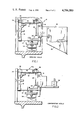
- FIG. 1 is an elevation partly in section of an electronic weighing scale provided with a receptacle for receiving the product to be weighed;
- FIG. 2 is an elevation partly in section of a scale embodying the same mass and dynamics as the weighing scale shown in FIG. 1 to which there is attached a weight corresponding to the weight of the product receiving receptacle;
- FIG. 3 diagrammatically illustrates the electronic control system designed to cancel out extraneous noise and vibration
- FIG. 4 graphically discloses the reduction in vibration that is the difference in scale signal output with and without the system disclosed therein.
- FIG. 1 there is shown an electronic weighing scale 10 comprising spaced, parallel, horizontally-disposed upper and lower pairs of stiff leaf springs 12--12 secured at their proximal ends to a frame member 14 and at their distal ends connected by a rigid member 16 to which is mounted a product-receiving receptacle 18 provided with a drop bottom 20.
- a strain gauge 22 in the form of a beam is rigidly attached at its proximal end 24 by means of bolts 26 to the frame member 14 between the spring of the upper pair of springs 12.
- a wire 25 is adjustably connected at its upper end by a threaded nut 28 to the distal end of the strain gauge.
- the lower end of wire is connected to a block 30 which, in turn, is connected by a spindle 32 to a dash pot 34 which damps oscillation of the structure.
- the pairs of stiff leaf springs 12--12 constitute a beam, the free end of which will deflect as product is delivered into the receptacle 18.
- the strain gauge 22 will, at the same time, be deflected in proportion to the amount of product dumped into the receptacle 18.
- the deflection in the strain gauge 22 is very small, to wit, in the order of 2 ⁇ 10 -3 inches per pound or 1.6 ⁇ 10 -4 inches per ounce and while this deflection is constant and highly repeatable, because it is low, noise signals of either mechanical or electrical origin will upset the system's operation. Electrical noise is usually higher in frequency than mechanical noise and can be filtered electronically. However, mechanical noise and vibration that occur at the same frequency as normal scale operation cannot be filtered without altering scale accuracy and response. It has been found that a scale system of this kind is inherently susceptible to free vibration and that normal floor vibration will cause sufficient beam deflection to produce a noise signal in the order of 0.04 ounces. If this vibration signal is not eliminated, an invalid weight readout to actual weight relationship will occur.
- the compensating scale 10 duplicates the mass and dynamics of the weighing scale, differing only from the weighing scale in that a weight 36 corresponding in weight to the product-receiving receptable 18 is substituted for the weighing receptacle. All of the other component parts of the compensating scale are identical as indicated by corresponding reference characters applied to the corresponding components.
- the electronic control for the weighing scale and the compensating scale is disclosed in FIG. 3 and is designed to convert the mechanical stresses developed by bending of the strain gauges 22 to electrical signals in such a way as to cancel out extraneous disturbances and thus measure the actual weight of the product delivered into the weighing receptacle 18 free of any error which might be caused by such extraneous disturbances.
- This is achieved, as shown in FIG. 3, by providing each of the respective strain gauges 22 with a wheatstone bridge 38 which is responsive to the deflections in the strain gauges 22 during the weighing operation to convert the deflection of the gauges to voltages in the form of signals which are transmitted to a common summing amplifier 40.
- the signal generated by the summing amplifier 40 is transmitted to a voltage comparator 42 which also receives a variable set point voltage 44. Balancing of the summing signal and the set point signal results in transmitting a signal to a switching amplifier 46 which, in turn, transmits a signal to a solenoid 48 which terminates feed of product to the receptacle 18 by closing an appropriate gate G in the product delivery conduit, not shown.
- a conductor 50 connected between the amplifiers 40 and 42 provides for weight readout or data acquisition for microprocessor control.
- instrument amplifiers 52, buffer amplifiers 54 and filter amplifiers 56 are connected to provide 180° out-of-phase current to the summing amplifier 40 which algebraically adds the signals from the respective bridges cancelling the common signal or noise component.
- the output from the strain gauges 38 is applied to the input of the instrument amplifiers 52.
- the purpose of the instrument amplifiers is to amplify the signals to a usable level.
- the gain factor of the instrument amplifiers 52 is set by the gain adjustment at 1400. This means that the voltage level at the point A is 1400 times higher than that of the instrument amplifiers input.
- the signals are then applied to the buffer amplifiers 54 for the purpose of increasing the signal current.
- the output from the buffer amplifiers 54 is applied to the input of the three-stage adjustable filter amplifiers 56.
- the filters 56 have a low frequency cutoff of 2 HZ.
- the purpose of the filter amplifiers is to eliminate all electrical signals above 2 HZ (2 cycles per second). Since a normal scale operation occurs at approximately 2 HZ, it is important to eliminate the spurious signals at other frequency that would cause false scale trip.
- the output from the filter amplifiers 56 is applied to one input of the summing amplifier 40 and the resultant output to one input of the voltage comparator 42.
- the other input 44 of the comparator 40 is used to manually adjust a set point voltage and when the signal voltage equals the preset voltage, an output signal is generated by the comparator.
- the comparator is used to derive a voltage to weight output signal.
- the output from the voltage amplifier is applied to the switch amplifier 46 and the switch amplifier is used to actuate the scale solenoid 48.
- the scale trip solenoid 48 releases the gate G to terminate product feed to the product receptacle 18.
- vibration cancellation devices derives from the fact that in virtually every major industry as a means of process control, microprocessors have been devised to provide output commands to a machine or process based on input signals from the machine or process.
- Microprocessor based controls for weighing and filling machines use weight related voltage signals from the scale control device to perform a process algorithm for the specific purpose of holding weightments at a specified weight.
- the purpose of the vibration cancellation device is to cancel low frequency mechanical vibrations that occur at the same frequency as the weighing operation. If the vibration signals are not eliminated, a false weight readout signal will occur.
- the readout data is used for statistical analysis for the purpose of making a precise adjustment to weight setpoint, it is important to insure the integrity of the weight readout data.
- the noise cancellation system described herein eliminates the effect of mechanical noise and vibration by using a compensating scale duplicating the mass and dynamics of the weight scale. All of the machine vibrations will be common to both weighing and compensating scales. Hence, the only force not common to both scales is that caused by the product filling the weight receptacle.
- the scale signal output (scale empty) was monitored at the final amplifier with a type 464 oscilloscope.
- Signal photos were taken with and without the cancellation beam, the results of which are depicted graphically in FIG. 4 which shows the signal output with cancellation A and without cancellation B.
- the oscillation 6 HZ apparent in FIG. 4 was caused from floor vibration and induced sufficient beam deflection to cause a quiescent voltage output equivalent to a 0.04 ounce weight load.
- the noise signal is attenuated to a level barely discernible at the output amplifier. It should be noted that this data was acquired under a relatively stable industrial environment under more austere conditions than in normal industrial use where vibration levels would be higher, making the noise cancellation beam more essential.
- strain gauges are described as first class beams, load cells may be substituted therefor.
Landscapes
- Physics & Mathematics (AREA)
- General Physics & Mathematics (AREA)
- Measurement Of Force In General (AREA)
- Vibration Prevention Devices (AREA)
Abstract
Description
Claims (13)
Priority Applications (2)
| Application Number | Priority Date | Filing Date | Title |
|---|---|---|---|
| US06/293,677 US4396080A (en) | 1981-08-17 | 1981-08-17 | Weighing system |
| GB08223284A GB2104667B (en) | 1981-08-17 | 1982-08-12 | Weighing system |
Applications Claiming Priority (1)
| Application Number | Priority Date | Filing Date | Title |
|---|---|---|---|
| US06/293,677 US4396080A (en) | 1981-08-17 | 1981-08-17 | Weighing system |
Publications (1)
| Publication Number | Publication Date |
|---|---|
| US4396080A true US4396080A (en) | 1983-08-02 |
Family
ID=23130075
Family Applications (1)
| Application Number | Title | Priority Date | Filing Date |
|---|---|---|---|
| US06/293,677 Expired - Lifetime US4396080A (en) | 1981-08-17 | 1981-08-17 | Weighing system |
Country Status (2)
| Country | Link |
|---|---|
| US (1) | US4396080A (en) |
| GB (1) | GB2104667B (en) |
Cited By (14)
| Publication number | Priority date | Publication date | Assignee | Title |
|---|---|---|---|---|
| US4553618A (en) * | 1982-08-20 | 1985-11-19 | Mettler-Waagen Gmbh | Weighing cell |
| US4593778A (en) * | 1983-06-21 | 1986-06-10 | Kabushiki Kaisha Ishida Koki Seisakusho | Weighing machine with dummy load cell for error correction |
| US4624331A (en) * | 1983-12-28 | 1986-11-25 | Kabushiki Kaisha Ishida Koki Seisakusho | Weight sensor with vibration error correction |
| US4656599A (en) * | 1983-11-09 | 1987-04-07 | Sartorius Gmbh | Electric balance |
| US4708215A (en) * | 1984-08-08 | 1987-11-24 | Ishida Scales Manufacturing Company, Ltd. | Automatic weighing system |
| US4751973A (en) * | 1987-09-16 | 1988-06-21 | Pitney Bowes Inc. | Load cell scale with reference channel for live load correction |
| US4926359A (en) * | 1983-04-14 | 1990-05-15 | Kabushiki Kaisha Ishida Koki Seisakusho | Weight sensing apparatus |
| US5050693A (en) * | 1987-09-30 | 1991-09-24 | Wirth Gallo Messtechnik Ag | Balance and process for calibrating and operating the balance |
| US5172783A (en) * | 1991-07-01 | 1992-12-22 | Pitney Bowes, Inc. | Weighing scale with validating reference channel |
| US5178227A (en) * | 1988-11-11 | 1993-01-12 | Scanvagt A/S | Weighing system, particularly a maritime weighing system |
| US6727438B1 (en) | 2002-05-15 | 2004-04-27 | Steve Stokes | Method for determining oil and grease content using a reference weight signal for live cancellation of disturbances in the weighting signal |
| US20150346019A1 (en) * | 2014-05-28 | 2015-12-03 | Seca Ag | Method and device for measuring the length and weight of a body |
| JP2016017888A (en) * | 2014-07-09 | 2016-02-01 | 株式会社イシダ | Weighing device |
| US10935416B1 (en) | 2013-12-18 | 2021-03-02 | Amazon Technologies, Inc. | System for generating compensated weight data using a gyroscope |
Families Citing this family (3)
| Publication number | Priority date | Publication date | Assignee | Title |
|---|---|---|---|---|
| GB2176897A (en) * | 1985-06-25 | 1987-01-07 | Hunting Hivolt Ltd | Weighing machine |
| EP1898193B1 (en) * | 2006-09-05 | 2016-06-01 | Mettler-Toledo GmbH | Force measuring device and reference unit |
| CN113853339B (en) * | 2019-05-22 | 2023-02-28 | I.M.A.工业机械自动装置股份公司 | Dispensing device for supplying an infusion product |
Citations (4)
| Publication number | Priority date | Publication date | Assignee | Title |
|---|---|---|---|---|
| US3322222A (en) * | 1964-11-12 | 1967-05-30 | Baur Fritz | Compensated electromagnetic balance |
| US3670833A (en) * | 1970-08-25 | 1972-06-20 | Yawata Iron & Steel Co | Method for measuring a weighing load rapidly |
| US4108263A (en) * | 1976-06-14 | 1978-08-22 | Focke & Pfuhl | Method and apparatus having a vibration-free measuring phase for automatically weighing bulk material, more particularly tobacco |
| US4212361A (en) * | 1978-02-24 | 1980-07-15 | Mettler Instruments Ag | Electrical scale with improved immunity to environmental disturbances |
-
1981
- 1981-08-17 US US06/293,677 patent/US4396080A/en not_active Expired - Lifetime
-
1982
- 1982-08-12 GB GB08223284A patent/GB2104667B/en not_active Expired
Patent Citations (4)
| Publication number | Priority date | Publication date | Assignee | Title |
|---|---|---|---|---|
| US3322222A (en) * | 1964-11-12 | 1967-05-30 | Baur Fritz | Compensated electromagnetic balance |
| US3670833A (en) * | 1970-08-25 | 1972-06-20 | Yawata Iron & Steel Co | Method for measuring a weighing load rapidly |
| US4108263A (en) * | 1976-06-14 | 1978-08-22 | Focke & Pfuhl | Method and apparatus having a vibration-free measuring phase for automatically weighing bulk material, more particularly tobacco |
| US4212361A (en) * | 1978-02-24 | 1980-07-15 | Mettler Instruments Ag | Electrical scale with improved immunity to environmental disturbances |
Cited By (15)
| Publication number | Priority date | Publication date | Assignee | Title |
|---|---|---|---|---|
| US4553618A (en) * | 1982-08-20 | 1985-11-19 | Mettler-Waagen Gmbh | Weighing cell |
| US4926359A (en) * | 1983-04-14 | 1990-05-15 | Kabushiki Kaisha Ishida Koki Seisakusho | Weight sensing apparatus |
| US4593778A (en) * | 1983-06-21 | 1986-06-10 | Kabushiki Kaisha Ishida Koki Seisakusho | Weighing machine with dummy load cell for error correction |
| US4656599A (en) * | 1983-11-09 | 1987-04-07 | Sartorius Gmbh | Electric balance |
| US4624331A (en) * | 1983-12-28 | 1986-11-25 | Kabushiki Kaisha Ishida Koki Seisakusho | Weight sensor with vibration error correction |
| US4708215A (en) * | 1984-08-08 | 1987-11-24 | Ishida Scales Manufacturing Company, Ltd. | Automatic weighing system |
| US4751973A (en) * | 1987-09-16 | 1988-06-21 | Pitney Bowes Inc. | Load cell scale with reference channel for live load correction |
| US5050693A (en) * | 1987-09-30 | 1991-09-24 | Wirth Gallo Messtechnik Ag | Balance and process for calibrating and operating the balance |
| US5178227A (en) * | 1988-11-11 | 1993-01-12 | Scanvagt A/S | Weighing system, particularly a maritime weighing system |
| US5172783A (en) * | 1991-07-01 | 1992-12-22 | Pitney Bowes, Inc. | Weighing scale with validating reference channel |
| US6727438B1 (en) | 2002-05-15 | 2004-04-27 | Steve Stokes | Method for determining oil and grease content using a reference weight signal for live cancellation of disturbances in the weighting signal |
| US10935416B1 (en) | 2013-12-18 | 2021-03-02 | Amazon Technologies, Inc. | System for generating compensated weight data using a gyroscope |
| US20150346019A1 (en) * | 2014-05-28 | 2015-12-03 | Seca Ag | Method and device for measuring the length and weight of a body |
| US9804019B2 (en) * | 2014-05-28 | 2017-10-31 | Seca Ag | Method and device for measuring the length and weight of a body |
| JP2016017888A (en) * | 2014-07-09 | 2016-02-01 | 株式会社イシダ | Weighing device |
Also Published As
| Publication number | Publication date |
|---|---|
| GB2104667A (en) | 1983-03-09 |
| GB2104667B (en) | 1986-06-18 |
Similar Documents
| Publication | Publication Date | Title |
|---|---|---|
| US4396080A (en) | Weighing system | |
| GB1586448A (en) | Electric mass measuring instruments | |
| US2767974A (en) | Weighing unit | |
| EP0103747B1 (en) | Load cell | |
| US3986571A (en) | Load-compensating weighing apparatus including signal modifying means | |
| US2421222A (en) | Multirange load measuring apparatus | |
| CA2072696C (en) | Weighing scale with validating reference channel | |
| EP0430695A2 (en) | Weighing apparatus | |
| EP0122796A1 (en) | Weighing apparatus | |
| US4294321A (en) | Position sensing and display means | |
| US5226496A (en) | Method and apparatus for fast determination of weights | |
| EP0534736B1 (en) | Scale for fast determination of weights | |
| US4258811A (en) | Electric mass and force measuring apparatus | |
| CN100595530C (en) | Weighing devices, especially multi-track weighing devices | |
| US5440076A (en) | Weight-checking apparatus | |
| EP0622617B1 (en) | Weighing machine with at least three dummy cells | |
| JP3834141B2 (en) | Vibratory conveying device for goods | |
| CA1158263A (en) | Differential weighing system providing improved signal to noise ratio | |
| EP0722084A1 (en) | Device for measuring the mass concentration of a mud mixture or similar mixture flowing through a pipe line | |
| KR910001147B1 (en) | Weighing device | |
| US20200056931A1 (en) | Calibrating a conveyor and metering device | |
| JP3836969B2 (en) | Vibratory conveying device for goods | |
| JP3581179B2 (en) | Mass or weight measuring device | |
| JPH08110261A (en) | Mass measuring device and weight measuring device | |
| Yamakawa et al. | Vibration compensation using dummy load-cell in dynamic mass measurement |
Legal Events
| Date | Code | Title | Description |
|---|---|---|---|
| AS | Assignment |
Owner name: PNEUMATIC SCALE CORPORATION, QUINCY, MA A CORP OF Free format text: ASSIGNMENT OF ASSIGNORS INTEREST.;ASSIGNOR:DEE, GERALD M.;REEL/FRAME:003910/0887 Effective date: 19810807 |
|
| STCF | Information on status: patent grant |
Free format text: PATENTED CASE |
|
| MAFP | Maintenance fee payment |
Free format text: PAYMENT OF MAINTENANCE FEE, 4TH YEAR, PL 96-517 (ORIGINAL EVENT CODE: M170); ENTITY STATUS OF PATENT OWNER: LARGE ENTITY Year of fee payment: 4 |
|
| FEPP | Fee payment procedure |
Free format text: PAYOR NUMBER ASSIGNED (ORIGINAL EVENT CODE: ASPN); ENTITY STATUS OF PATENT OWNER: LARGE ENTITY |
|
| MAFP | Maintenance fee payment |
Free format text: PAYMENT OF MAINTENANCE FEE, 8TH YEAR, PL 96-517 (ORIGINAL EVENT CODE: M171); ENTITY STATUS OF PATENT OWNER: LARGE ENTITY Year of fee payment: 8 |
|
| MAFP | Maintenance fee payment |
Free format text: PAYMENT OF MAINTENANCE FEE, 12TH YEAR, LARGE ENTITY (ORIGINAL EVENT CODE: M185); ENTITY STATUS OF PATENT OWNER: LARGE ENTITY Year of fee payment: 12 |
|
| FEPP | Fee payment procedure |
Free format text: PAYOR NUMBER ASSIGNED (ORIGINAL EVENT CODE: ASPN); ENTITY STATUS OF PATENT OWNER: LARGE ENTITY Free format text: PAYER NUMBER DE-ASSIGNED (ORIGINAL EVENT CODE: RMPN); ENTITY STATUS OF PATENT OWNER: LARGE ENTITY |