US4394692A - Housing assembly for an electrical apparatus - Google Patents
Housing assembly for an electrical apparatus Download PDFInfo
- Publication number
- US4394692A US4394692A US06/325,582 US32558281A US4394692A US 4394692 A US4394692 A US 4394692A US 32558281 A US32558281 A US 32558281A US 4394692 A US4394692 A US 4394692A
- Authority
- US
- United States
- Prior art keywords
- housing
- end cap
- housing assembly
- platform
- camera
- Prior art date
- Legal status (The legal status is an assumption and is not a legal conclusion. Google has not performed a legal analysis and makes no representation as to the accuracy of the status listed.)
- Expired - Fee Related
Links
Images


Classifications
-
- H—ELECTRICITY
- H04—ELECTRIC COMMUNICATION TECHNIQUE
- H04N—PICTORIAL COMMUNICATION, e.g. TELEVISION
- H04N23/00—Cameras or camera modules comprising electronic image sensors; Control thereof
- H04N23/50—Constructional details
- H04N23/51—Housings
Definitions
- This invention relates generally to housing assemblies for electrical apparatus, and more particularly to housings which protect electrical equipment used for transmission or reception of light and other electromagnetic signals.
- Housing assemblies have been widely used in the prior art to protect electrical apparatus such as television surveillance cameras from theft, shock and other physical disturbance. If properly constructed, these assemblies may also be useful in isolating the enclosed electrical device from dust and other atmospheric contaminants, as well as providing a more visually attractive casing than that of the device itself.
- the present invention therefore incorporates a variety of novel and cost-efficient features which minimize the time that would otherwise be spent removing parts of the housing assembly to reach and adjust the electrical apparatus therein, or to make connections to terminals on or about the apparatus.
- the invention further provides these features while maintaining an environment for the apparatus which protects it and its connecting cables from shock, strain and external contaminants.
- Another object is to provide an improved housing assembly which saves production costs by using a plurality of identical housing members to perform different structural functions.
- a housing assembly for use with a television surveillance camera or the like.
- the housing includes an extruded stationary base with identical frame-shaped front and rear fixed members, and a removable extruded cover which latches to the front and rear members.
- a television camera inside the housing may receive optical images through the front frame member and transmit these images via cables leaving the housing through the rear frame member.
- a molded rubber end cap is adapted for detachable connection to the rear frame member, sealing out dust and contaminants when in place.
- the detachable end cap includes dustproof openings for the entry of cables into the rear of the housing with projections for strain relief incorporated into the openings.
- the openings are further connected by a slit in the rubber end cap, permitting cables to be inserted through the end cap without removing terminal connecting members.
- the periphery of the end cap is also formed with reinforcing gussets to provide shock protection at the rear edges of the housing assembly.
- the extruded base further includes tracks for supporting a planar camera platform and permitting the platform to slide longitudinally with respect to the base. Specially designed quick release clamps permit the platform to be secured to the tracks when the camera is properly positioned relative to the front frame member of the housing.
- FIG. 1 is a perspective view of the housing assembly as viewed from the left rear corner thereof;
- FIG. 2 is a cross-sectional view of the housing assembly taken through line 2--2 of FIG. 1;
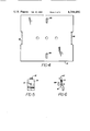
- FIG. 3 is a front elevational view of the extruded base portion or lower half housing of the housing assembly shown in FIG. 1, with a camera platform and quick-release clamps attached.
- FIG. 4 is a plan view of a camera platform which may be clamped to the lower half housing as illustrated in FIG. 3;
- FIG. 5 is a plan view of a quick-release clamp used for holding the camera platform of FIG. 4 in place within the lower half housing as illustrated in FIG. 3;
- FIG. 6 is a side elevational view of the clamp illustrated in FIG. 5, with a threaded bolt shown in phantom view;
- FIG. 7 is an elevational view of the back of one of the two frame-shaped members which are attached to either end of the lower half housing of FIG. 3;
- FIG. 8 is an elevational view of a detachable end cap having four strain relief members, which fits over the rear frame member illustrated in FIG. 7.
- FIG. 1 is a perspective view of a camera housing assembly 1 incorporating the invention, as seen from the left rear corner of the housing.
- the housing assembly 1 comprises a longitudinally extending lower half housing 2, which is substantially U-shaped in a lateral cross-section, and a longitudinally extending upper half housing 3, also U-shaped in lateral cross-section, which is designed to matingly engage the lower half housing 2 along the sides of the housing assembly 1.
- a stationary front housing member 5 is secured to the lower half housing, as by threaded screws, and a stationary rear housing member 7 is similarly secured to the rear of the lower half housing 2.
- Slide latches 11, mounted in longitudinal channels 13 formed on both sides of the upper half housing 3, are adapted to slide in their respective channels and mate with notches in the stationary front and rear housing caps to hold the upper half housing 3 in place atop the lower half housing 2.
- the elastic or rubber end cap 9 may be formed with several cylindrical projections 15 for providing strain relief to electrical cables which connect a camera inside the housing to an external signal processing apparatus.
- the rubber end cap 9 is also adapted for easy detachment from the stationary rear housing member 7, in order to provide access to the rear portion of the camera mounted inside the housing assembly 1.
- FIG. 2 is a cross-sectional view of housing assembly 1 with the upper half housing 3 removed, taken through section line 2--2.
- the lower half housing 2 which is also illustrated in a front elevational view in FIG. 3, preferably consists of an extruded plastic or aluminum shell formed with vertical support walls 17 and horizontal support walls 19 for supporting a camera platform 21, and longitudinally extending channels 23 for providing stationary mounting of the housing members 5 and 7 to the ends of the lower half housing 2 via screws 25 or the like.
- a camera 27 (shown in imaginary lines in FIG. 2 for reference purposes) may be mounted to camera platform 21 with conventional fastening means, such as a mounting stud and threaded screw 29. The camera platform 21 and attached camera 27 may then be mounted in the lower half housing 2 and secured by clamps 31 to the horizontal support walls 19.
- This arrangement permits rapid adjustment of the camera position inside the housing assembly 1 by loosening the clamps 31 and sliding the camera platform 21 along the horizontal support walls 19 until the camera lens is as close to the front of the housing assembly 1 as is possible.
- the walls of the housing assembly 1 may limit the viewing angle of an improperly positioned camera; therefore, the distance from the camera lens to the front of the assembly should ordinarily be kept to a minimum to avoid a tunnel effect being created by the walls of the housing assembly 1.
- FIGS. 4, 5 and 6 illustrate the preferred forms of the camera platform 21 in plan view and the clamps 31 in plan and side views.
- the platform 21 is formed with two slots 85 which are dimensioned to accept both anti-torque tab 87 on clamp 31 and bolt 89, and to permit lateral sliding movement of the clamps 31 within their respective slots 85.
- clamp 31 may be positioned under platform 21 with tab 87 in slot 85, and bolt 89 is inserted through the top of platform 21 and screws into the threaded aperture 91 on clamp 31, for securing it to the platform 21 as shown in FIG. 3.
- anti-torque tab 87 in slot 85 prevents the clamp 31 from rotating when the bolt 89 is tightened, thus facilitating longitudinal adjustment of platform 21 by permitting rapid locking and unlocking of the clamp 31 on the horizontal support wall 19 without access to the underside of the camera platform 21.
- Guide tabs 93 may also be formed at the front and rear of platform 21 to fit between the vertical support walls 17 on the lower half housing 2 and act as guides for permitting a smooth sliding movement of platform 21 when the clamps 31 are unlocked, as illustrated in FIG. 3.
- the length of slot 85 is designed to permit clamp 31 to slide toward the center of platform 21 when bolt 89 is loosened, thus moving the clamp out of engagement with horizontal support wall 19 and permitting rapid removal of platform 21 from the housing 1 for servicing of the camera.
- Front and rear housing members 5 and 7, illustrated in side cross-section in FIG. 2 and in an elevational view in FIG. 7, are preferably identical pieces injection molded from a hard plastic such as ABS or Noryl N190.
- These members comprise a generally rectangular frame 33 with an outer periphery 35 which conforms to the contours of the mated upper and lower half housings 2 and 3.
- the inner perimeter 37 of the frame borders a generally rectangular area 38 through which the inside of the housing assembly may be accessed.
- the frame 33 is formed with four substantially cylindrical columns 39 inside of the outer periphery 35 which are positioned for alignment with the longitudinal channels 23 of the lower half housing 2.
- the columns 39 are dimensioned to accept a screw 25 for attaching the front and rear housing caps to the lower half housing.
- the frames 33 are further formed with a cavity 41 on both sides of the frame which is adapted to accept the sliding latches 11 on the upper half housing 3 to secure that housing in place atop the lower half housing 2 when the sliding latches 11 are engaged therein.
- Support projections 43 are formed inside the outer periphery 35 of the top of the frame 33, extending beyond the frame for providing support to the top of the upper half housing 3 when mated with the lower half housing 2.
- the inner perimeter 37 of the frame 33 is formed with four retaining fingers 45 having a lip portion 47 as seen in FIGS. 2 and 7. In the embodiment described, the four retaining fingers 45 of the front housing member 5 are used to hold a transparent window 49 in place inside the inner perimeter 37 of the housing member 5, as shown in FIG. 2.
- a camera 27 is positioned inside the housing assembly 1 with the front of the camera nearest to the window 49, which protects the camera lens from dust and other contamination.
- Removable end cap 9 is designed to snap in place over the stationary rear housing member 7 in order to seal off the rectangular area 38 of that member and further provide strain relief for cables entering the rear of the housing assembly 1.
- the end cap 9 is preferably made of a synthetic elastomer in which the cylindrical projections 15, provided for strain relief, may be integrally formed.
- the elastic properties of the end cap 9 provide an additional benefit of insulating the camera inside the housing assembly 1 from shocks applied to the rear of the housing.
- the end cap 9 comprises a generally rectangular, resilient, frame-shaped portion 51 with a vertical wall 53 inside the frame. As seen in the cross-sectional view of FIG.
- the frame portion is generally U-shaped in cross-section, and is designed to fit over the rearmost part of the stationary rear housing member 7.
- the outer peripheral wall 55 of the resilient frame 51 abuts the outer periphery 35 of the rear housing member 7 along a junction line 57, conforming substantially to the shape of the rear housing member 7 and the mated upper and lower half housings 2 and 3.
- the inner sill 59 of the resilient frame 51 conforms to and substantially covers the corresponding inner sill 60 of the rear housing member 7.
- Peripherally spaced gussets 61 formed in the frame portion 51 inside the junction 62 of the outer wall 55 and the outer face 63, conform to the curved surface 65 of the rear housing member 7 adding support to the end cap 9 and providing additional cushioning against shock loads on the corner junctions 62 of the end cap 9.
- the vertical wall 53 of the end cap 9 covers the rectangular area 38 bordered by the inner perimeter 37 of the rear housing member 7, protecting the interior of the housing assembly 1 from dust and other contaminants.
- the end cap 9 is attached to the housing member 7 via four resilient, notched protrusions 67 formed in the corners of the interior surface 69 of the vertical wall 53.
- a tightly fitting retaining band 70 made of spring steel or other suitable material, may also be fitted inside the frame portion 51 to lock the end cap 9 in place as seen in FIG. 8.
- Protrusions 67 shown in cross-section in FIG. 2 and in phantom lines in FIG. 8, have a generally conical tip 71 attached to the vertical wall 53 by a trunk portion 73.
- the space between the base of the conical tip 71 and the vertical wall 53 forms a notch 75 in which the inner perimeter 37 of the rear housing member 7 is seated, when the end cap 9 is snapped onto it.
- the surface 76 of the base of the cone 71 is preferably slanted outwardly so that the protrusions will move out of engagement with the inner perimeter 37 of the housing member 7 when moderate force is applied to remove the end cap 9, just as the slanted surface of the cone 71 aids in the elastic displacement of the protrusions 67 when the end cap 9 is snap fitted onto the housing member 7.
- the exterior surface 77 of the vertical wall 53 is formed with a set of hollow, substantially cylindrical projections 15, which provide strain relief for cables entering housing assembly 1.
- the projections 15 may be formed with a longitudinal split 79 which allows the resilient walls of the projection to expand outwardly and provide a snug fit around the walls of a cable which is inserted through the projection. Tightly wound springs 80 may then be press fit onto the cylindrical projections 15 to clamp the projection walls around their respective cables, thus preventing distortion of the end cap 9 at splits 79 and 95 due to cable pressure.
- the portion of the vertical wall 53 at the base of the cylindrical projections 15 may further be provided with radial cuts 81, forming a number of pie-shaped wedges 83 as seen in FIG. 5. The wedges 83 will be inwardly splayed when a cable is inserted through a cylindrical projection 15 into the housing assembly 1, the wedges forming a seal around the cable to prevent dust or moisture from entering the assembly.
- the resilient vertical wall 53 is formed with a slit 95 connecting the cylindrical projections 15. This feature facilitates the entry of transmission lines and other cables into the housing assembly 1 without the need to remove connectors which may be attached to the ends of the cables. This entry may be accomplished by separating the resilient vertical wall 53 at the slit 95, inserting the connector through the separated slit 95, and sliding the cable along this opening until it seats in a desired cylindrical projection 15. When the cable is properly seated, the resilient vertical wall 53 will return to its original configuration, sealing the inside of the housing assembly 1 from dust and other contaminants as described previously.
Abstract
Description
Claims (7)
Priority Applications (1)
| Application Number | Priority Date | Filing Date | Title |
|---|---|---|---|
| US06/325,582 US4394692A (en) | 1981-11-27 | 1981-11-27 | Housing assembly for an electrical apparatus |
Applications Claiming Priority (1)
| Application Number | Priority Date | Filing Date | Title |
|---|---|---|---|
| US06/325,582 US4394692A (en) | 1981-11-27 | 1981-11-27 | Housing assembly for an electrical apparatus |
Publications (1)
| Publication Number | Publication Date |
|---|---|
| US4394692A true US4394692A (en) | 1983-07-19 |
Family
ID=23268480
Family Applications (1)
| Application Number | Title | Priority Date | Filing Date |
|---|---|---|---|
| US06/325,582 Expired - Fee Related US4394692A (en) | 1981-11-27 | 1981-11-27 | Housing assembly for an electrical apparatus |
Country Status (1)
| Country | Link |
|---|---|
| US (1) | US4394692A (en) |
Cited By (26)
| Publication number | Priority date | Publication date | Assignee | Title |
|---|---|---|---|---|
| US4485407A (en) * | 1981-11-07 | 1984-11-27 | Grundig E. M.V. | Television camera for indoor and outdoor use |
| US5221964A (en) * | 1991-08-05 | 1993-06-22 | Dalsa Inc | Electronically expandable modular ccd camera |
| US5381176A (en) * | 1991-08-11 | 1995-01-10 | Sony Corporation | Miniaturized video camera |
| US5394208A (en) * | 1993-10-22 | 1995-02-28 | Eastman Kodak Company | Environmental enclosure for a camera |
| US5455625A (en) * | 1993-09-23 | 1995-10-03 | Rosco Inc. | Video camera unit, protective enclosure and power circuit for same, particularly for use in vehicles |
| US5589294A (en) * | 1993-06-17 | 1996-12-31 | Tulip Corporation | Side wall electricity battery terminal |
| US5610656A (en) * | 1994-02-22 | 1997-03-11 | Videor Technical E. Hartig Gmbh | Protective housing for optical equipment |
| US5814421A (en) * | 1996-12-20 | 1998-09-29 | Tulip Corporation | Method and apparatus for making a battery terminal and a battery terminal made thereby |
| US6039582A (en) * | 1998-09-30 | 2000-03-21 | Motorola, Inc. | Discharge lamp ballast housing with solderless connectors |
| USRE37709E1 (en) | 1991-02-11 | 2002-05-21 | Ultrak, Inc. | System for recording and modifying behavior of passenger in passenger vehicles |
| US20030095800A1 (en) * | 2001-11-21 | 2003-05-22 | Thales Avionics In-Flights Systems, Llc | Universal security camera |
| US6637952B2 (en) | 2000-11-01 | 2003-10-28 | Pelco | Notched camera case with swivel base |
| USRE38967E1 (en) | 1991-11-12 | 2006-02-07 | K & F Manufacturing, Ltd. | Video monitor and housing assembly |
| US8118499B2 (en) | 2010-05-19 | 2012-02-21 | LIR Systems, Inc. | Infrared camera assembly systems and methods |
| USD666660S1 (en) * | 2011-04-27 | 2012-09-04 | Lytro, Inc. | Camera |
| US8976511B1 (en) * | 2007-10-16 | 2015-03-10 | Traxxas Lp | Protective enclosure for model vehicle |
| USD741933S1 (en) * | 2014-05-08 | 2015-10-27 | Axis Ab | Monitoring camera |
| USD757344S1 (en) * | 2014-08-26 | 2016-05-24 | Ip Holdings, Llc | Ballast housing |
| USD761481S1 (en) * | 2014-08-26 | 2016-07-12 | Ip Holdings, Llc | Ballast housing |
| USD780691S1 (en) | 2015-05-20 | 2017-03-07 | Ip Holdings, Llc | Remote ballast |
| USD786475S1 (en) | 2012-04-17 | 2017-05-09 | Ip Holdings, Llc | Ballast |
| USD812670S1 (en) | 2015-03-16 | 2018-03-13 | Axis Ab | Monitoring camera |
| US10201106B2 (en) | 2013-06-28 | 2019-02-05 | Traxxas Lp | Watertight sealing apparatus and method for electronic enclosure |
| USD855238S1 (en) | 2017-10-27 | 2019-07-30 | Hgci, Inc. | Ballast |
| US20190377245A1 (en) * | 2018-06-11 | 2019-12-12 | Mgmd Brainpower Llc | Camera accessory housing device |
| USD871654S1 (en) | 2017-10-30 | 2019-12-31 | Hgci, Inc. | Light fixture |
Citations (2)
| Publication number | Priority date | Publication date | Assignee | Title |
|---|---|---|---|---|
| US4281343A (en) * | 1980-04-28 | 1981-07-28 | George Monteiro | Underwater video camera housing |
| US4344092A (en) * | 1980-10-21 | 1982-08-10 | Circon Corporation | Miniature video camera means for video system |
-
1981
- 1981-11-27 US US06/325,582 patent/US4394692A/en not_active Expired - Fee Related
Patent Citations (2)
| Publication number | Priority date | Publication date | Assignee | Title |
|---|---|---|---|---|
| US4281343A (en) * | 1980-04-28 | 1981-07-28 | George Monteiro | Underwater video camera housing |
| US4344092A (en) * | 1980-10-21 | 1982-08-10 | Circon Corporation | Miniature video camera means for video system |
Cited By (46)
| Publication number | Priority date | Publication date | Assignee | Title |
|---|---|---|---|---|
| US4485407A (en) * | 1981-11-07 | 1984-11-27 | Grundig E. M.V. | Television camera for indoor and outdoor use |
| USRE37709E1 (en) | 1991-02-11 | 2002-05-21 | Ultrak, Inc. | System for recording and modifying behavior of passenger in passenger vehicles |
| US5221964A (en) * | 1991-08-05 | 1993-06-22 | Dalsa Inc | Electronically expandable modular ccd camera |
| US5381176A (en) * | 1991-08-11 | 1995-01-10 | Sony Corporation | Miniaturized video camera |
| USRE38967E1 (en) | 1991-11-12 | 2006-02-07 | K & F Manufacturing, Ltd. | Video monitor and housing assembly |
| US5589294A (en) * | 1993-06-17 | 1996-12-31 | Tulip Corporation | Side wall electricity battery terminal |
| US5455625A (en) * | 1993-09-23 | 1995-10-03 | Rosco Inc. | Video camera unit, protective enclosure and power circuit for same, particularly for use in vehicles |
| US5394208A (en) * | 1993-10-22 | 1995-02-28 | Eastman Kodak Company | Environmental enclosure for a camera |
| US5610656A (en) * | 1994-02-22 | 1997-03-11 | Videor Technical E. Hartig Gmbh | Protective housing for optical equipment |
| US5814421A (en) * | 1996-12-20 | 1998-09-29 | Tulip Corporation | Method and apparatus for making a battery terminal and a battery terminal made thereby |
| US6039582A (en) * | 1998-09-30 | 2000-03-21 | Motorola, Inc. | Discharge lamp ballast housing with solderless connectors |
| US6637952B2 (en) | 2000-11-01 | 2003-10-28 | Pelco | Notched camera case with swivel base |
| US20030095800A1 (en) * | 2001-11-21 | 2003-05-22 | Thales Avionics In-Flights Systems, Llc | Universal security camera |
| US20050063696A1 (en) * | 2001-11-21 | 2005-03-24 | Thales Avionics, Inc. | Universal security camera |
| US6824317B2 (en) | 2001-11-21 | 2004-11-30 | Thales Avionics, Inc. | Universal security camera |
| US7088525B2 (en) | 2001-11-21 | 2006-08-08 | Thales Avionics, Inc. | Universal security camera |
| US20060268435A1 (en) * | 2001-11-21 | 2006-11-30 | Thales Avionics, Inc. | Universal security camera |
| US20060268116A1 (en) * | 2001-11-21 | 2006-11-30 | Thales Avionics, Inc. | Universal security camera |
| US7330649B2 (en) | 2001-11-21 | 2008-02-12 | Thales Avionics, Inc. | Universal security camera |
| US7649696B2 (en) | 2001-11-21 | 2010-01-19 | Thales Avionics, Inc. | Universal security camera |
| US8976511B1 (en) * | 2007-10-16 | 2015-03-10 | Traxxas Lp | Protective enclosure for model vehicle |
| US9844736B1 (en) * | 2007-10-16 | 2017-12-19 | Traxxas Lp | Protective enclosure for model vehicle |
| US8982541B1 (en) * | 2007-10-16 | 2015-03-17 | Traxxas Lp | Protective enclosure for model vehicle |
| US10646788B2 (en) * | 2007-10-16 | 2020-05-12 | Traxxas Lp | Protective enclosure for model vehicle |
| US10300398B2 (en) * | 2007-10-16 | 2019-05-28 | Traxxas L.P. | Protective enclosure for model vehicle |
| US20180104606A1 (en) * | 2007-10-16 | 2018-04-19 | Traxxas Lp | Protective enclosure for model vehicle |
| US11154788B2 (en) * | 2007-10-16 | 2021-10-26 | Traxxas Lp | Protective enclosure for a model vehicle |
| US20190275438A1 (en) * | 2007-10-16 | 2019-09-12 | Traxxas Lp | Protective enclosure for model vehicle |
| US8118499B2 (en) | 2010-05-19 | 2012-02-21 | LIR Systems, Inc. | Infrared camera assembly systems and methods |
| USD666660S1 (en) * | 2011-04-27 | 2012-09-04 | Lytro, Inc. | Camera |
| USD786475S1 (en) | 2012-04-17 | 2017-05-09 | Ip Holdings, Llc | Ballast |
| US10201106B2 (en) | 2013-06-28 | 2019-02-05 | Traxxas Lp | Watertight sealing apparatus and method for electronic enclosure |
| USD748710S1 (en) | 2013-11-13 | 2016-02-02 | Axis Ab | Monitoring camera |
| USD741933S1 (en) * | 2014-05-08 | 2015-10-27 | Axis Ab | Monitoring camera |
| USD761481S1 (en) * | 2014-08-26 | 2016-07-12 | Ip Holdings, Llc | Ballast housing |
| USD757344S1 (en) * | 2014-08-26 | 2016-05-24 | Ip Holdings, Llc | Ballast housing |
| USD812670S1 (en) | 2015-03-16 | 2018-03-13 | Axis Ab | Monitoring camera |
| USD835697S1 (en) * | 2015-03-16 | 2018-12-11 | Axis Ab | Monitoring camera |
| USD835037S1 (en) | 2015-05-20 | 2018-12-04 | Ip Holdings, Llc | Remote ballast |
| USD780691S1 (en) | 2015-05-20 | 2017-03-07 | Ip Holdings, Llc | Remote ballast |
| USD855238S1 (en) | 2017-10-27 | 2019-07-30 | Hgci, Inc. | Ballast |
| USD1007045S1 (en) | 2017-10-27 | 2023-12-05 | Hgci, Inc. | Ballast |
| USD871654S1 (en) | 2017-10-30 | 2019-12-31 | Hgci, Inc. | Light fixture |
| USD996696S1 (en) | 2017-10-30 | 2023-08-22 | Hgci, Inc. | Light fixture |
| US20190377245A1 (en) * | 2018-06-11 | 2019-12-12 | Mgmd Brainpower Llc | Camera accessory housing device |
| US11215906B2 (en) * | 2018-06-11 | 2022-01-04 | Mgmd Brainpower Llc | Camera accessory housing device |
Similar Documents
| Publication | Publication Date | Title |
|---|---|---|
| US4394692A (en) | Housing assembly for an electrical apparatus | |
| US6072125A (en) | Noise absorbing apparatus | |
| CA1036701A (en) | Housing assemblies for electrical apparatus | |
| US11677223B2 (en) | Cable grounding assembly for telecommunications enclosure | |
| KR940017004A (en) | Panel Mount Electrical Connectors With Sealing System | |
| US9363922B2 (en) | Horizontal manager for equipment racks and enclosures | |
| KR20100112085A (en) | An interconnection system | |
| WO2006052364A1 (en) | Environmental seal for network interface device | |
| US11050113B2 (en) | Battery holder | |
| GB2047644A (en) | Case for mounting on motor cycles | |
| EP0464663B1 (en) | Projection-type television set | |
| KR20200108440A (en) | Modular single bolt fuse holder | |
| US4450963A (en) | Portable protective housing for sensitive apparatus such as electrical and electronic equipment | |
| US3758716A (en) | Television receiver mounting apparatus | |
| CA1138244A (en) | Simplified type television camera | |
| WO2021085839A1 (en) | Door and home appliance having the same | |
| GB2151859A (en) | Enclosure for electrical devices | |
| KR102083227B1 (en) | Box for preventing rain | |
| JPH02204700A (en) | Setting device for cooling fan | |
| EP3767764B1 (en) | Mounting system for electric or electronic device | |
| WO2003079088A1 (en) | Thermal window systems | |
| JP3666684B2 (en) | Optical cable connection case | |
| JPH0679186U (en) | Fixed structure of cover | |
| JPH0524725B2 (en) | ||
| CA1161917A (en) | Modular block base and bracket assembly |
Legal Events
| Date | Code | Title | Description |
|---|---|---|---|
| AS | Assignment |
Owner name: VICON INDUSTRIES, INC., 125 EAST BETHPAGE ROAD, PL Free format text: ASSIGNMENT OF ASSIGNORS INTEREST.;ASSIGNORS:RANDMAE, REIN S.;WHITAKER, TODD H.;REEL/FRAME:003955/0533 Effective date: 19811109 Owner name: VICON INDUSTRIES, INC., A CORP. OF NY, NEW YORK Free format text: ASSIGNMENT OF ASSIGNORS INTEREST;ASSIGNORS:RANDMAE, REIN S.;WHITAKER, TODD H.;REEL/FRAME:003955/0533 Effective date: 19811109 |
|
| MAFP | Maintenance fee payment |
Free format text: PAYMENT OF MAINTENANCE FEE, 4TH YEAR, PL 96-517 (ORIGINAL EVENT CODE: M170); ENTITY STATUS OF PATENT OWNER: LARGE ENTITY Year of fee payment: 4 |
|
| FEPP | Fee payment procedure |
Free format text: MAINTENANCE FEE REMINDER MAILED (ORIGINAL EVENT CODE: REM.); ENTITY STATUS OF PATENT OWNER: LARGE ENTITY |
|
| FEPP | Fee payment procedure |
Free format text: PAYOR NUMBER ASSIGNED (ORIGINAL EVENT CODE: ASPN); ENTITY STATUS OF PATENT OWNER: LARGE ENTITY |
|
| LAPS | Lapse for failure to pay maintenance fees | ||
| STCH | Information on status: patent discontinuation |
Free format text: PATENT EXPIRED DUE TO NONPAYMENT OF MAINTENANCE FEES UNDER 37 CFR 1.362 |
|
| FP | Lapsed due to failure to pay maintenance fee |
Effective date: 19910721 |