US4393736A - Cutter for a moving strand - Google Patents
Cutter for a moving strand Download PDFInfo
- Publication number
- US4393736A US4393736A US06/252,720 US25272081A US4393736A US 4393736 A US4393736 A US 4393736A US 25272081 A US25272081 A US 25272081A US 4393736 A US4393736 A US 4393736A
- Authority
- US
- United States
- Prior art keywords
- strand
- path
- movement
- arm
- knee
- Prior art date
- Legal status (The legal status is an assumption and is not a legal conclusion. Google has not performed a legal analysis and makes no representation as to the accuracy of the status listed.)
- Expired - Fee Related
Links
Images


Classifications
-
- B—PERFORMING OPERATIONS; TRANSPORTING
- B23—MACHINE TOOLS; METAL-WORKING NOT OTHERWISE PROVIDED FOR
- B23D—PLANING; SLOTTING; SHEARING; BROACHING; SAWING; FILING; SCRAPING; LIKE OPERATIONS FOR WORKING METAL BY REMOVING MATERIAL, NOT OTHERWISE PROVIDED FOR
- B23D15/00—Shearing machines or shearing devices cutting by blades which move parallel to themselves
- B23D15/12—Shearing machines or shearing devices cutting by blades which move parallel to themselves characterised by drives or gearings therefor
- B23D15/14—Shearing machines or shearing devices cutting by blades which move parallel to themselves characterised by drives or gearings therefor actuated by fluid or gas pressure
-
- Y—GENERAL TAGGING OF NEW TECHNOLOGICAL DEVELOPMENTS; GENERAL TAGGING OF CROSS-SECTIONAL TECHNOLOGIES SPANNING OVER SEVERAL SECTIONS OF THE IPC; TECHNICAL SUBJECTS COVERED BY FORMER USPC CROSS-REFERENCE ART COLLECTIONS [XRACs] AND DIGESTS
- Y10—TECHNICAL SUBJECTS COVERED BY FORMER USPC
- Y10T—TECHNICAL SUBJECTS COVERED BY FORMER US CLASSIFICATION
- Y10T83/00—Cutting
- Y10T83/202—With product handling means
- Y10T83/2066—By fluid current
- Y10T83/207—By suction means
-
- Y—GENERAL TAGGING OF NEW TECHNOLOGICAL DEVELOPMENTS; GENERAL TAGGING OF CROSS-SECTIONAL TECHNOLOGIES SPANNING OVER SEVERAL SECTIONS OF THE IPC; TECHNICAL SUBJECTS COVERED BY FORMER USPC CROSS-REFERENCE ART COLLECTIONS [XRACs] AND DIGESTS
- Y10—TECHNICAL SUBJECTS COVERED BY FORMER USPC
- Y10T—TECHNICAL SUBJECTS COVERED BY FORMER US CLASSIFICATION
- Y10T83/00—Cutting
- Y10T83/869—Means to drive or to guide tool
- Y10T83/8735—With means providing for plural steps in tool stroke
-
- Y—GENERAL TAGGING OF NEW TECHNOLOGICAL DEVELOPMENTS; GENERAL TAGGING OF CROSS-SECTIONAL TECHNOLOGIES SPANNING OVER SEVERAL SECTIONS OF THE IPC; TECHNICAL SUBJECTS COVERED BY FORMER USPC CROSS-REFERENCE ART COLLECTIONS [XRACs] AND DIGESTS
- Y10—TECHNICAL SUBJECTS COVERED BY FORMER USPC
- Y10T—TECHNICAL SUBJECTS COVERED BY FORMER US CLASSIFICATION
- Y10T83/00—Cutting
- Y10T83/869—Means to drive or to guide tool
- Y10T83/8752—Tool moves work to and against cooperating tool
Definitions
- This invention relates to the processing of strands and, more particularly, to the processing of a plurality of strands advancing away from a continuously operating source.
- strand as used herein is intended to include either a single filament, a gathered plurality, or warp of such filaments as well as yarns, webs, and the like produced from the filaments.
- the cutter is a vital component of the system and while the cutting devices of the prior art have proven satisfactory for cutting a few strands at one time, improvement is needed to reliably handle large warps of up to 40 ends.
- the apparatus of this invention is located in a machine for processing at least one continuously advancing strand and comprises a support situated adjacent the path of travel of the strand, a bed knife attached to said support and located below the path of the strand, and an arm normally positioned above the path of the strand for movement across the strand path to engagement with said bed knife.
- a linkage mechanism having a knee is pivotally connected at one end to the support while the other end of the linkage mounts said arm for said movement.
- a first motive means is coupled to said linkage for imparting said movement.
- a second motive means is engageable with the knee of said linkage to hold the knee in an over-the-center position and limit movement of said arm to a location slightly above the strand. When energized the second motive means moves the knee over center and allows the arm to complete its movement to engagement with said bed knife.
- the apparatus includes a waste jet or the like for removing the advancing strand after it has been severed. Included, also, is a strand isolation bar mounted for transverse movement across the strand path and above the waste jet.
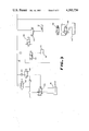
- FIG. 1 is a block diagram of the process to which this invention applies.
- FIG. 2 is a schematic diagram of FIG. 1 showing a restringing operation after a cutdown.
- FIG. 3 is an elevation view of the apparatus of this invention including the isolation bar and the waste jet.
- FIG. 4 is a view of FIG. 3 taken along line 4--4.
- FIG. 5 is a schematic diagram of the pneumatic control system of the invention.
- the process chosen for illustration of the apparatus of this invention is a continuous process for manufacturing staple yarns from a continuously running warp 10 and includes, as shown in FIG. 1, a spinning module 12 where filament forming material is extruded from spinnerets, a cutdown module 14, a process module 16 wherein various steps such as drawing and annealing are performed, and cutter 18 which cuts the warp into staple lengths and feeds cut staple yarn to a baler (not shown).
- the function of the cutdown module 14 is to sever the warp 10 and divert it to the waste hamper 11 when a defective condition arises during the processing steps which follow extrusion.
- FIG. 2 a portion of the process for manufacturing that is the spinning module and the cutter module is shown schematically to include spinnerets 20 extruding threadlines 22 over finish rolls 24 around guides 26 into warp sheet 10.
- the warp sheet passes around a polished chrome driven roll 28 and its associated idler rolls 29 past and underneath an isolation bar 30 which is extendable and retractable across the path of the warp 10 then over waste jet 32 and through cutter unit 34 to a second driven roll 36.
- An interlacing jet 21 is located below warp 10 and is moveable from one position to another in the spinning module.
- a sucker gun 23 is used in association with the interlace jet during restringing after the warp has been cut and all ends are running into waste jet 32.
- the isolation bar 30 is extended across the warp path above the waste jet 32 to isolate ends being restrung from the ends running to the waste jet. Initially, one end at one spinning position is cut from the waste jet 32 and directed over the top of the isolation bar, through the cutter, and on to the process module. Ends are then progressively cut out of the waste jet 32 at the spinning position and tied into the ends running over the isolation bar 30 using interlace jet 21 and sucker gun 23. The isolation bar positions the ends outside the aspirating zone of the waste jet 32. When all the ends have been restrung, the jet 32 is turned off and the isolation bar 30 is retracted to reposition the warp in its normal path directly over the waste jet 32.
- the cutter jet device comprises generally a frame 40 supporting a jet assembly 32 which has an upwardly opening slot inlet, not shown, on its upper surface 33.
- Bracket 41 carries arm 44 which is shown in the string up position. When the arm 44 is in this position, a warp sheet 10 of running filaments may be inserted through slot 45 to a position extending approximately from lengths 46 and 47 of the underside of arm 44.
- a bed knife 43 is supported by frame 40 for engagement with the lower edge of arm 44 during its downward travel.
- a pneumatic cylinder 48 is fixed to frame 40 with the travel of its piston 49 directed upwardly in the direction of arm 44. Fastened to piston 49 by a pin 42 is a link 50.
- This link rotates at one end about a pin 51 in frame 40 and is also attached to the lower end of arm 44 by a pin 39.
- Link 50 is joined at its other end to a link 54 by means of a slot 50a in link 50 carrying a pin 54a in the end of link 54.
- Link 54 is joined to link 55 by a pin 56 to form a knee at this joint.
- the other end of link 55 pivots about a pin 57 in frame 40 and is spring loaded by spring 58 to frame 40.
- a flat-ended pneumatic cylinder 60 is attached to frame 40 with its extensible rod 61 directed toward the knee between links 54 and 55. The rod 61 when fully retracted as shown bears upon the knee formed by links 54, 55 which are in an over-the-center relationship and prevented from further movement by rod 61.
- a linkage connected between associated pneumatic cylinders 48 and 60 and arm 44 provides a means to lock the arm into the position shown.
- the cutter is taken to the armed mode by charging cylinder 48 on the down side. This will cause link 50 to lower cutter 44 to a position just above the yarn lines. This will also lock the cutter in this position by the previously described mechanism.
- solenoids 106, 107 and 108 directs air to the waste jet 32, retracts the isolation bar 30 by acting through 4-way spool valve 109 and cylinder 110. After a delay of 400 milliseconds, an electrical signal is sent to solenoid valve 112 which extends rod 61 of cylinder 60 which pushes the knee of the linkage between links 54, 55 over center allowing piston 49 of cylinder 48 to retract fully causing the cutting action between arm 44 and bed knife 43 to cut the warp 10 which is picked up by the jet.
Landscapes
- Engineering & Computer Science (AREA)
- Mechanical Engineering (AREA)
- Preliminary Treatment Of Fibers (AREA)
Abstract
Description
Claims (2)
Priority Applications (1)
| Application Number | Priority Date | Filing Date | Title |
|---|---|---|---|
| US06/252,720 US4393736A (en) | 1981-04-10 | 1981-04-10 | Cutter for a moving strand |
Applications Claiming Priority (1)
| Application Number | Priority Date | Filing Date | Title |
|---|---|---|---|
| US06/252,720 US4393736A (en) | 1981-04-10 | 1981-04-10 | Cutter for a moving strand |
Publications (1)
| Publication Number | Publication Date |
|---|---|
| US4393736A true US4393736A (en) | 1983-07-19 |
Family
ID=22957241
Family Applications (1)
| Application Number | Title | Priority Date | Filing Date |
|---|---|---|---|
| US06/252,720 Expired - Fee Related US4393736A (en) | 1981-04-10 | 1981-04-10 | Cutter for a moving strand |
Country Status (1)
| Country | Link |
|---|---|
| US (1) | US4393736A (en) |
Citations (8)
| Publication number | Priority date | Publication date | Assignee | Title |
|---|---|---|---|---|
| US3090268A (en) * | 1959-07-17 | 1963-05-21 | Du Pont | Apparatus for severing fed strands and subsequent handling thereof |
| US3175290A (en) * | 1962-08-22 | 1965-03-30 | Du Pont | Yarn handling apparatus |
| US3241234A (en) * | 1964-03-10 | 1966-03-22 | Monsanto Co | Yarn aspirator with severing means |
| US3564958A (en) * | 1967-07-17 | 1971-02-23 | Leesona Corp | Yarn handling apparatus |
| US3807270A (en) * | 1968-11-06 | 1974-04-30 | Rieter Ag Maschf | Apparatus for cutting a thread on a draw-spin-winding machine |
| US3864999A (en) * | 1973-06-05 | 1975-02-11 | Du Pont | Doffing cutter with remote pickup |
| US3960305A (en) * | 1974-07-11 | 1976-06-01 | E. I. Du Pont De Nemours And Company | Slot vacuum jet |
| US4214357A (en) * | 1978-02-16 | 1980-07-29 | Purpose Engineers Limited | Punching device |
-
1981
- 1981-04-10 US US06/252,720 patent/US4393736A/en not_active Expired - Fee Related
Patent Citations (8)
| Publication number | Priority date | Publication date | Assignee | Title |
|---|---|---|---|---|
| US3090268A (en) * | 1959-07-17 | 1963-05-21 | Du Pont | Apparatus for severing fed strands and subsequent handling thereof |
| US3175290A (en) * | 1962-08-22 | 1965-03-30 | Du Pont | Yarn handling apparatus |
| US3241234A (en) * | 1964-03-10 | 1966-03-22 | Monsanto Co | Yarn aspirator with severing means |
| US3564958A (en) * | 1967-07-17 | 1971-02-23 | Leesona Corp | Yarn handling apparatus |
| US3807270A (en) * | 1968-11-06 | 1974-04-30 | Rieter Ag Maschf | Apparatus for cutting a thread on a draw-spin-winding machine |
| US3864999A (en) * | 1973-06-05 | 1975-02-11 | Du Pont | Doffing cutter with remote pickup |
| US3960305A (en) * | 1974-07-11 | 1976-06-01 | E. I. Du Pont De Nemours And Company | Slot vacuum jet |
| US4214357A (en) * | 1978-02-16 | 1980-07-29 | Purpose Engineers Limited | Punching device |
Similar Documents
| Publication | Publication Date | Title |
|---|---|---|
| US6056227A (en) | Device for automatically replacing thread bobbins and spooling device with replacement unit | |
| NL8202215A (en) | Rinse-free weaving machine, provided with means for removing faulty weft threads from the weaving box. | |
| US4087308A (en) | Apparatus and method for making reinforced elastomeric fabric | |
| US3915398A (en) | Automatic doffing apparatus | |
| US4393736A (en) | Cutter for a moving strand | |
| DE68917931T2 (en) | APPARATUS AND METHOD FOR FEEDING FLEXIBLE BOWS. | |
| US4947633A (en) | Process and an arrangement for producing packages to be used as feeding packages for twisting | |
| US5771825A (en) | Embroidery machine with automatic thread changer | |
| AU631038B2 (en) | High speed cutter for aramids | |
| US5188304A (en) | Device and process for the handling and the control of the thread on a coner machine during the operation of spool change and of thread joining | |
| US4998566A (en) | Liquid warp splicing system for a warp in a loom | |
| EP0997416B1 (en) | Method for leading a web onto a roller and device to execute the method | |
| JPH06136634A (en) | Thread turning device in air-operated loom | |
| US5083715A (en) | Apparatus for loosening an end of textile material | |
| US3090268A (en) | Apparatus for severing fed strands and subsequent handling thereof | |
| JPH0735625B2 (en) | Method and device for separating warp thread scraps | |
| US4893762A (en) | Winding machine with a device to sever the winding roll from the web | |
| EP0738795B1 (en) | Automatic cop changing device for a weaving machine | |
| JPS6316511B2 (en) | ||
| US5158120A (en) | Clearing a weft yarn break in a loom | |
| GB2183194A (en) | Apparatus for cutting a tying member of a bale | |
| US5150640A (en) | High-speed cutter for yarns | |
| US4078736A (en) | Automatic doffing method | |
| EP0517664A1 (en) | Weft handling apparatus in a shuttleless loom | |
| US3149515A (en) | Process for severing fed strands and subsequent handling thereof |
Legal Events
| Date | Code | Title | Description |
|---|---|---|---|
| AS | Assignment |
Owner name: E.I. DU PONT DE NEMOURS AND COMPANY, WILMINGTON, D Free format text: ASSIGNMENT OF ASSIGNORS INTEREST.;ASSIGNORS:CLARK, THOMAS R.;LILLMARS, ALVIN E.;ROTH, ELWOOD A.;AND OTHERS;REEL/FRAME:003892/0339;SIGNING DATES FROM 19810331 TO 19810408 |
|
| MAFP | Maintenance fee payment |
Free format text: PAYMENT OF MAINTENANCE FEE, 4TH YEAR, PL 96-517 (ORIGINAL EVENT CODE: M170); ENTITY STATUS OF PATENT OWNER: LARGE ENTITY Year of fee payment: 4 |
|
| MAFP | Maintenance fee payment |
Free format text: PAYMENT OF MAINTENANCE FEE, 8TH YEAR, PL 96-517 (ORIGINAL EVENT CODE: M171); ENTITY STATUS OF PATENT OWNER: LARGE ENTITY Year of fee payment: 8 |
|
| FEPP | Fee payment procedure |
Free format text: MAINTENANCE FEE REMINDER MAILED (ORIGINAL EVENT CODE: REM.); ENTITY STATUS OF PATENT OWNER: LARGE ENTITY |
|
| LAPS | Lapse for failure to pay maintenance fees | ||
| FP | Lapsed due to failure to pay maintenance fee |
Effective date: 19950719 |
|
| STCH | Information on status: patent discontinuation |
Free format text: PATENT EXPIRED DUE TO NONPAYMENT OF MAINTENANCE FEES UNDER 37 CFR 1.362 |