US4383754A - Multi-bounce, folded path scanning system - Google Patents
Multi-bounce, folded path scanning system Download PDFInfo
- Publication number
- US4383754A US4383754A US06/323,154 US32315481A US4383754A US 4383754 A US4383754 A US 4383754A US 32315481 A US32315481 A US 32315481A US 4383754 A US4383754 A US 4383754A
- Authority
- US
- United States
- Prior art keywords
- mirrors
- pair
- mirror
- tracks
- slidably mounted
- Prior art date
- Legal status (The legal status is an assumption and is not a legal conclusion. Google has not performed a legal analysis and makes no representation as to the accuracy of the status listed.)
- Expired - Fee Related
Links
Images


Classifications
-
- G—PHYSICS
- G03—PHOTOGRAPHY; CINEMATOGRAPHY; ANALOGOUS TECHNIQUES USING WAVES OTHER THAN OPTICAL WAVES; ELECTROGRAPHY; HOLOGRAPHY
- G03B—APPARATUS OR ARRANGEMENTS FOR TAKING PHOTOGRAPHS OR FOR PROJECTING OR VIEWING THEM; APPARATUS OR ARRANGEMENTS EMPLOYING ANALOGOUS TECHNIQUES USING WAVES OTHER THAN OPTICAL WAVES; ACCESSORIES THEREFOR
- G03B27/00—Photographic printing apparatus
- G03B27/32—Projection printing apparatus, e.g. enlarger, copying camera
- G03B27/52—Details
- G03B27/522—Projection optics
- G03B27/525—Projection optics for slit exposure
- G03B27/526—Projection optics for slit exposure in which the projection optics move
Definitions
- the instant invention relates to an optical path folding system and more particularly to such a system utilizing a pair of mirrors forming an acute angle therebetween for compact packaging of scanning devices or line imaging optical systems.
- One device which serves to shorten the required separation between the various elements in an optical system is an optical path folding system including a first mirror and a second mirror opposing the first mirror and forming an acute angle therewith, the mirrors being separated by a predetermined distance, whereby one end of the mirrors is more open than the other end of the mirrors, as described in co-pending patent application Ser. No. 311,696 filed Oct. 15, 1981 and assigned to Pitney Bowes Inc.
- the optical path length between the two mirrors increases at a faster rate than the separation. If such a pair of mirrors is moved on a traveling carriage so that the distance moved were compensated for by changing the mirror separation, a great distance of carriage travel could be compensated for with a relatively small change in mirror separation.
- the instant invention accordingly provides a mechanical means of insuring accurate mirror alignment and separation throughout the carriage travel.
- a multi-bounce, folded path scanning system which comprises a first and second pair of stationary tracks, the second pair of tracks being angled with respect to the first pair of tracks, a movable carriage slidably mounted on said first pair of stationary tracks, a first mirror fixedly mounted on said movable carriage, and a second mirror slidably mounted on said second pair of stationary tracks and opposing said first mirror and forming an acute angle therewith, said mirrors being separated by a predetermined distance, whereby one end of said mirrors is more open than the other end of said mirrors.
- the scanning system also includes an input light ray entering at the more open end of the mirrors and incident upon said first mirror at a predetermined angle, wherein said ray is reflected off each mirror a predetermined multiplicity of times and exits said mirrors at the more open end, and means for translating said first and second mirrors, wherein the predetermined distance between the mirrors increases as the mirrors are translated while the correct angular relationship between the mirrors is maintained.
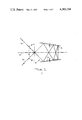
- FIG. 1 is a schematic, side elevational view of the mirrors used in the folded path scanning system of the instant invention
- FIG. 2 is a vertical sectional view of one embodiment of the instant invention showing the mirrors close together at the beginning of a cycle;
- FIG. 3 is the same as FIG. 2 except it shows the mirrors further apart at the end of the cycle
- FIG. 4 is a partially broken away, perspective view of the embodiment shown in FIG. 3;
- FIG. 5 is a vertical sectional view of a second embodiment of the instant invention showing the mirrors close together at the beginning of a cycle;
- FIG. 6 is the same as FIG. 5 except it shows the mirrors further apart at the end of the cycle
- FIG. 7 is a perspective view of the embodiment shown in FIG. 6;
- FIG. 1 in which there is seen a first mirror 10 and a second mirror 12 opposing the first mirror 10 and separated therefrom by a predetermined distance.
- a center line 14 is indicated between the opposing mirrors 10 and 12, and each of the mirrors 10 and 12 forms an acute angle ⁇ with the center line 14.
- An input light ray 16 from a bundle of light rays (not shown) is provided by any conventional means at a predetermined angle ⁇ which is the angle between the input ray 16 and a plane perpendicular to the center line 14.
- ⁇ is the angle between the input ray 16 and a plane perpendicular to the center line 14.
- n represents the total number of times the input ray 16 bounces off the two mirrors 10 and 12.
- n would be 6
- ⁇ is 45 degrees
- ⁇ is 7.5 degrees.
- the lower limit of n is 4, inasmuch as the input ray 16 must bounce off each of the mirrors 10 and 12 at least twice in order to take advantage of the unique and useful compacting characteristics of the folding system described.
- the practical upper limit for n is primarily determined by the acceptable reflective losses and optical degradations associated with the optical quality of the mirrors 10 and 12.
- the angle ⁇ is limited in smallness by the interference caused by the mirror 12 and the input ray 16 which, in actual use, will be a bundle of rays. As angle ⁇ is reduced, the input ray 16 approaches the edge of mirror 12 until some angle at which the edge of mirror 12 intersects the input bundle causing unacceptable loss. Angle ⁇ may be as large as 90 degrees, at which point the input and output rays shown would be parallel. The user of the instant invention would determine the degree of deviation acceptable or desirable between the input rays 16 and exit rays 20.
- the input light ray 16 enters the space between the mirrors 10 and 12 at the more open end 18 and also exits the mirrors 10 and 12 at the more open end 18 as illustrated by the exit light ray 20.
- the exit ray 20 finally strikes a lens 21.
- FIGS. 2-4 in which there is seen a pair of supporting sidewalls 22 and 24.
- the sidewall 22 includes slots or tracks 26, 28, 30, and 32, while the sidewall 24 includes slots or tracks 34, 36, 38 and 40.
- a movable carriage 42 consisting of a pair of angled arms 44 and 46 supporting and flanking either side of a rectangular plate 48 (see FIG. 4) rides in the horizontal tracks 26, 32, 34 and 40 by means of pins 50 and 52, which ride in the horizontal tracks 26 and 32 respectively and pins 54 and 56 which ride in the horizontal tracks 34 and 40 respectively.
- the second mirror 12 is secured to the underside of the rectangular plate 48.
- the first mirror 10 is secured to the top side of a second rectangular plate 58 mounted on a pair of brackets 60 and 62.
- Each of the brackets 60 and 62 includes a pair of pins 64 and 66, and 68 and 70 respectively which ride in angled tracks 28, 30, 36 and 38 respectively.
- the brackets 60 and 62 each include additional pins 72 and 74 respectively which ride in slots 76 and 78 respectively located in the lower sections 80 and 82 of the angled arms 44 and 46 respectively.
- a document illuminator 84 for use with a photocopying machine (not shown) is shown (see FIGS. 2 and 3) secured to an illuminator support 86 consisting of opposed supporting arms 88 and 90 each having upper sections 92 and 94 respectively.
- Each of the upper sections 92 and 94 has a channel 96 and 98 respectively for receiving pins 100 and 102 respectively extending from the brackets 60 and 62 respectively.
- two opposing mirrors 10 and 12 are spaced relatively close together at the beginning of a cycle as seen in FIG. 2.
- the movable carriage 42 is then caused to be translated along the horizontal tracks 26, 32, 34 and 40 to the left to the position shown in FIGS. 3 and 4 by conventional means (not shown).
- the motion of the carriage 42 drives the mirror 10 simultaneously along the angled tracks 28, 30, 36 and 38 and the slots 76 and 78 in the movable carriage 42, thereby insuring the correct angular and positional relationship between the two mirrors 10 and 12.
- the illuminator support 86 is driven by the mirror 10, and maintains the correct positional relationship for the illuminator 84 to illuminate the scanned document (not shown).
- FIGS. 5-7 A second embodiment of the instant invention is seen in FIGS. 5-7, in which there is seen a pair of horizontal rods 120 and 122 and a second pair of angled rods 124 and 126, all of which are supported by conventional means not shown.
- An upper rectangular plate 128 having flanges 130 and 132 and supporting a mirror 134 on its underside rides on the horizontal rods 120 and 122 by means of a pair of bearings 136 and 138 which are secured through a pair of pins 140 and 142 respectively to the flanges 130 and 132 respectively of the plate 128.
- the flanges 130 and 132 each include parallel slots 144 and 146 respectively which are discussed in greater detail hereinbelow.
- a second mirror 148 is secured to the top side of a second rectangular plate 150 having a pair of flanges 152 and 154.
- the second rectangular plate 150 rides on the angled rods 124 and 126 by means of a pair of bearings 156 and 158 which are secured through a pair of pins 160 and 162 respectively to the flanges 152 and 154 of the plate 150.
- the flanges 152 and 154 each include parallel slots 164 and 166.
- the two mirrors 134 and 148 are connected with each other through a pair of scissor jacks 168 and 170 having pivotable legs 172 and 174, and 176 and 178 respectively.
- the legs 172 and 174 both have ends which ride in the slot 144 as well as ends which ride in the slot 164, while the legs 176 and 178 have ends which ride in the slot 146 as well as ends which ride in the slot 166.
- the two opposing mirrors 134 and 148 are spaced relatively close together at the beginning of a cycle as seen in FIG. 5.
- the upper mirror 134 is then caused to be translated along the horizontal rods 120 and 122 to the left to the position shown in FIGS. 6 and 7 by conventional means (not shown).
- the motion of the mirror 134 drives the mirror 148 along the angled rods 124 and 126 and the scissor jacks 168 and 170 open up simultaneously by sliding in the parallel slots 144, 146, 164 and 166 to permit the mirrors 134 and 148 to separate while maintaining the correct angular relationship.
- the optical path length is defined as the distance from the point at which the input ray 16 first strikes the mirror 10 to the lens 21.
- the mirrors 10 and 12 in the course of moving about 9.25 inches from right to left, separate a distance of about two inches, with the path length being about 10.7 inches, to provide a path length to separation ratio of approximately 5.35:1, which demonstrates that a great distance of mirror travel can be compensated for with a relatively small change in mirror separation.
- FIGS. 5-7 The same results are obtained as well with the embodiment shown in FIGS. 5-7.
Landscapes
- Physics & Mathematics (AREA)
- Optics & Photonics (AREA)
- General Physics & Mathematics (AREA)
- Facsimile Scanning Arrangements (AREA)
- Optical Systems Of Projection Type Copiers (AREA)
Abstract
Description
θ=φ/n
Claims (4)
Priority Applications (1)
| Application Number | Priority Date | Filing Date | Title |
|---|---|---|---|
| US06/323,154 US4383754A (en) | 1981-11-20 | 1981-11-20 | Multi-bounce, folded path scanning system |
Applications Claiming Priority (1)
| Application Number | Priority Date | Filing Date | Title |
|---|---|---|---|
| US06/323,154 US4383754A (en) | 1981-11-20 | 1981-11-20 | Multi-bounce, folded path scanning system |
Publications (1)
| Publication Number | Publication Date |
|---|---|
| US4383754A true US4383754A (en) | 1983-05-17 |
Family
ID=23257938
Family Applications (1)
| Application Number | Title | Priority Date | Filing Date |
|---|---|---|---|
| US06/323,154 Expired - Fee Related US4383754A (en) | 1981-11-20 | 1981-11-20 | Multi-bounce, folded path scanning system |
Country Status (1)
| Country | Link |
|---|---|
| US (1) | US4383754A (en) |
Cited By (1)
| Publication number | Priority date | Publication date | Assignee | Title |
|---|---|---|---|---|
| US4812917A (en) * | 1986-03-20 | 1989-03-14 | Ricoh Company, Ltd. | Device for reducing document in size having two facing non-parallel mirrors |
Citations (2)
| Publication number | Priority date | Publication date | Assignee | Title |
|---|---|---|---|---|
| US3531183A (en) * | 1967-10-30 | 1970-09-29 | Honeywell Inc | Light beam deflector |
| SU566227A1 (en) * | 1976-01-19 | 1977-07-25 | Специальное Конструкторское Бюро Оргтехники | Apparatus for optical scanning of the original image in an electrophotographic copier |
-
1981
- 1981-11-20 US US06/323,154 patent/US4383754A/en not_active Expired - Fee Related
Patent Citations (2)
| Publication number | Priority date | Publication date | Assignee | Title |
|---|---|---|---|---|
| US3531183A (en) * | 1967-10-30 | 1970-09-29 | Honeywell Inc | Light beam deflector |
| SU566227A1 (en) * | 1976-01-19 | 1977-07-25 | Специальное Конструкторское Бюро Оргтехники | Apparatus for optical scanning of the original image in an electrophotographic copier |
Cited By (1)
| Publication number | Priority date | Publication date | Assignee | Title |
|---|---|---|---|---|
| US4812917A (en) * | 1986-03-20 | 1989-03-14 | Ricoh Company, Ltd. | Device for reducing document in size having two facing non-parallel mirrors |
Similar Documents
| Publication | Publication Date | Title |
|---|---|---|
| EP0027373A1 (en) | Raster input scanner including at least one array of image viewing elements adjustably mounted on a support | |
| US4113367A (en) | Roof reflective polygon scanning apparatus | |
| US6582088B2 (en) | Optical path folding apparatus | |
| US4029409A (en) | Multi-mode optical scanning system | |
| US2792448A (en) | Facsimile scanning apparatus | |
| US4050780A (en) | Optical system for a scanning apparatus with reflector pairs at each end | |
| US4383754A (en) | Multi-bounce, folded path scanning system | |
| US6850347B2 (en) | Scanning module | |
| US4372670A (en) | Precession scanning system | |
| CA1058435A (en) | Optical system for a scanning apparatus | |
| JPH07327109A (en) | Reader | |
| JPS62145960A (en) | Picture reader | |
| US4349271A (en) | Image projecting system | |
| GB2108283A (en) | Optical path folding system | |
| US4571065A (en) | Scale factor changing mechanism for copying machine | |
| US4497617A (en) | Optical system utilizing a variable focal length reflector lens | |
| JP3363582B2 (en) | Document reading device | |
| JPS5837670A (en) | Slit exposure optical device | |
| KR100389871B1 (en) | Apparatus for moving scanning carriage in image read-out device | |
| JPS6059340A (en) | Magnification varying mechanism of scanning optical system of copying machine | |
| JPS59125720A (en) | Device for converting magnification of image of copying machine | |
| US3572927A (en) | Reprographic scanning optics | |
| JPH0346864A (en) | Image reader | |
| JPS6236627A (en) | Optical scanning device | |
| JPS61285437A (en) | Scanning exposure device |
Legal Events
| Date | Code | Title | Description |
|---|---|---|---|
| AS | Assignment |
Owner name: PITNEY BOWES, INC., WALTER H. WHEELER, JR. DRIVE, Free format text: ASSIGNMENT OF ASSIGNORS INTEREST.;ASSIGNOR:KLEINSCHMITT, DAVID;REEL/FRAME:003953/0206 Effective date: 19811105 Owner name: PITNEY BOWES, INC., A CORP. OF DE, CONNECTICUT Free format text: ASSIGNMENT OF ASSIGNORS INTEREST;ASSIGNOR:KLEINSCHMITT, DAVID;REEL/FRAME:003953/0206 Effective date: 19811105 |
|
| MAFP | Maintenance fee payment |
Free format text: PAYMENT OF MAINTENANCE FEE, 4TH YEAR, PL 96-517 (ORIGINAL EVENT CODE: M170); ENTITY STATUS OF PATENT OWNER: LARGE ENTITY Year of fee payment: 4 |
|
| FEPP | Fee payment procedure |
Free format text: PAYOR NUMBER ASSIGNED (ORIGINAL EVENT CODE: ASPN); ENTITY STATUS OF PATENT OWNER: LARGE ENTITY |
|
| FEPP | Fee payment procedure |
Free format text: PAYOR NUMBER ASSIGNED (ORIGINAL EVENT CODE: ASPN); ENTITY STATUS OF PATENT OWNER: LARGE ENTITY Free format text: PAYER NUMBER DE-ASSIGNED (ORIGINAL EVENT CODE: RMPN); ENTITY STATUS OF PATENT OWNER: LARGE ENTITY |
|
| MAFP | Maintenance fee payment |
Free format text: PAYMENT OF MAINTENANCE FEE, 8TH YEAR, PL 96-517 (ORIGINAL EVENT CODE: M171); ENTITY STATUS OF PATENT OWNER: LARGE ENTITY Year of fee payment: 8 |
|
| FEPP | Fee payment procedure |
Free format text: PAYER NUMBER DE-ASSIGNED (ORIGINAL EVENT CODE: RMPN); ENTITY STATUS OF PATENT OWNER: LARGE ENTITY |
|
| FEPP | Fee payment procedure |
Free format text: MAINTENANCE FEE REMINDER MAILED (ORIGINAL EVENT CODE: REM.); ENTITY STATUS OF PATENT OWNER: LARGE ENTITY |
|
| LAPS | Lapse for failure to pay maintenance fees | ||
| FP | Lapsed due to failure to pay maintenance fee |
Effective date: 19950517 |
|
| STCH | Information on status: patent discontinuation |
Free format text: PATENT EXPIRED DUE TO NONPAYMENT OF MAINTENANCE FEES UNDER 37 CFR 1.362 |