US4376668A - Apparatus for and method of making V-belts - Google Patents
Apparatus for and method of making V-belts Download PDFInfo
- Publication number
- US4376668A US4376668A US06/328,338 US32833881A US4376668A US 4376668 A US4376668 A US 4376668A US 32833881 A US32833881 A US 32833881A US 4376668 A US4376668 A US 4376668A
- Authority
- US
- United States
- Prior art keywords
- belting
- belt
- channel
- slot
- slots
- Prior art date
- Legal status (The legal status is an assumption and is not a legal conclusion. Google has not performed a legal analysis and makes no representation as to the accuracy of the status listed.)
- Expired - Fee Related
Links
- 238000004519 manufacturing process Methods 0.000 title claims description 10
- 238000005520 cutting process Methods 0.000 claims abstract description 29
- 239000000463 material Substances 0.000 claims abstract description 21
- 238000010438 heat treatment Methods 0.000 claims abstract description 13
- 238000000034 method Methods 0.000 claims abstract description 8
- 229920001778 nylon Polymers 0.000 claims abstract description 7
- 239000004677 Nylon Substances 0.000 claims abstract description 5
- 230000003014 reinforcing effect Effects 0.000 abstract description 5
- 239000000835 fiber Substances 0.000 description 4
- 238000005304 joining Methods 0.000 description 4
- 238000004073 vulcanization Methods 0.000 description 2
- BTFMCMVEUCGQDX-UHFFFAOYSA-N 1-[10-[3-[4-(2-hydroxyethyl)-1-piperidinyl]propyl]-2-phenothiazinyl]ethanone Chemical compound C12=CC(C(=O)C)=CC=C2SC2=CC=CC=C2N1CCCN1CCC(CCO)CC1 BTFMCMVEUCGQDX-UHFFFAOYSA-N 0.000 description 1
- 230000015572 biosynthetic process Effects 0.000 description 1
- 239000011248 coating agent Substances 0.000 description 1
- 238000000576 coating method Methods 0.000 description 1
- 230000000694 effects Effects 0.000 description 1
- 239000013536 elastomeric material Substances 0.000 description 1
- 238000009413 insulation Methods 0.000 description 1
- 239000002184 metal Substances 0.000 description 1
- 238000012986 modification Methods 0.000 description 1
- 230000004048 modification Effects 0.000 description 1
- 229960004265 piperacetazine Drugs 0.000 description 1
- 239000004033 plastic Substances 0.000 description 1
Images
Classifications
-
- F—MECHANICAL ENGINEERING; LIGHTING; HEATING; WEAPONS; BLASTING
- F16—ENGINEERING ELEMENTS AND UNITS; GENERAL MEASURES FOR PRODUCING AND MAINTAINING EFFECTIVE FUNCTIONING OF MACHINES OR INSTALLATIONS; THERMAL INSULATION IN GENERAL
- F16G—BELTS, CABLES, OR ROPES, PREDOMINANTLY USED FOR DRIVING PURPOSES; CHAINS; FITTINGS PREDOMINANTLY USED THEREFOR
- F16G7/00—V-belt fastenings
- F16G7/02—V-belt fastenings locked, e.g. riveted
-
- B—PERFORMING OPERATIONS; TRANSPORTING
- B26—HAND CUTTING TOOLS; CUTTING; SEVERING
- B26D—CUTTING; DETAILS COMMON TO MACHINES FOR PERFORATING, PUNCHING, CUTTING-OUT, STAMPING-OUT OR SEVERING
- B26D7/00—Details of apparatus for cutting, cutting-out, stamping-out, punching, perforating, or severing by means other than cutting
- B26D7/0006—Means for guiding the cutter
-
- B—PERFORMING OPERATIONS; TRANSPORTING
- B29—WORKING OF PLASTICS; WORKING OF SUBSTANCES IN A PLASTIC STATE IN GENERAL
- B29C—SHAPING OR JOINING OF PLASTICS; SHAPING OF MATERIAL IN A PLASTIC STATE, NOT OTHERWISE PROVIDED FOR; AFTER-TREATMENT OF THE SHAPED PRODUCTS, e.g. REPAIRING
- B29C65/00—Joining or sealing of preformed parts, e.g. welding of plastics materials; Apparatus therefor
- B29C65/02—Joining or sealing of preformed parts, e.g. welding of plastics materials; Apparatus therefor by heating, with or without pressure
- B29C65/18—Joining or sealing of preformed parts, e.g. welding of plastics materials; Apparatus therefor by heating, with or without pressure using heated tools
-
- B—PERFORMING OPERATIONS; TRANSPORTING
- B29—WORKING OF PLASTICS; WORKING OF SUBSTANCES IN A PLASTIC STATE IN GENERAL
- B29C—SHAPING OR JOINING OF PLASTICS; SHAPING OF MATERIAL IN A PLASTIC STATE, NOT OTHERWISE PROVIDED FOR; AFTER-TREATMENT OF THE SHAPED PRODUCTS, e.g. REPAIRING
- B29C65/00—Joining or sealing of preformed parts, e.g. welding of plastics materials; Apparatus therefor
- B29C65/48—Joining or sealing of preformed parts, e.g. welding of plastics materials; Apparatus therefor using adhesives, i.e. using supplementary joining material; solvent bonding
- B29C65/4805—Joining or sealing of preformed parts, e.g. welding of plastics materials; Apparatus therefor using adhesives, i.e. using supplementary joining material; solvent bonding characterised by the type of adhesives
- B29C65/483—Reactive adhesives, e.g. chemically curing adhesives
- B29C65/4835—Heat curing adhesives
-
- B—PERFORMING OPERATIONS; TRANSPORTING
- B29—WORKING OF PLASTICS; WORKING OF SUBSTANCES IN A PLASTIC STATE IN GENERAL
- B29C—SHAPING OR JOINING OF PLASTICS; SHAPING OF MATERIAL IN A PLASTIC STATE, NOT OTHERWISE PROVIDED FOR; AFTER-TREATMENT OF THE SHAPED PRODUCTS, e.g. REPAIRING
- B29C65/00—Joining or sealing of preformed parts, e.g. welding of plastics materials; Apparatus therefor
- B29C65/48—Joining or sealing of preformed parts, e.g. welding of plastics materials; Apparatus therefor using adhesives, i.e. using supplementary joining material; solvent bonding
- B29C65/50—Joining or sealing of preformed parts, e.g. welding of plastics materials; Apparatus therefor using adhesives, i.e. using supplementary joining material; solvent bonding using adhesive tape, e.g. thermoplastic tape; using threads or the like
-
- B—PERFORMING OPERATIONS; TRANSPORTING
- B29—WORKING OF PLASTICS; WORKING OF SUBSTANCES IN A PLASTIC STATE IN GENERAL
- B29C—SHAPING OR JOINING OF PLASTICS; SHAPING OF MATERIAL IN A PLASTIC STATE, NOT OTHERWISE PROVIDED FOR; AFTER-TREATMENT OF THE SHAPED PRODUCTS, e.g. REPAIRING
- B29C65/00—Joining or sealing of preformed parts, e.g. welding of plastics materials; Apparatus therefor
- B29C65/48—Joining or sealing of preformed parts, e.g. welding of plastics materials; Apparatus therefor using adhesives, i.e. using supplementary joining material; solvent bonding
- B29C65/50—Joining or sealing of preformed parts, e.g. welding of plastics materials; Apparatus therefor using adhesives, i.e. using supplementary joining material; solvent bonding using adhesive tape, e.g. thermoplastic tape; using threads or the like
- B29C65/5007—Joining or sealing of preformed parts, e.g. welding of plastics materials; Apparatus therefor using adhesives, i.e. using supplementary joining material; solvent bonding using adhesive tape, e.g. thermoplastic tape; using threads or the like characterised by the structure of said adhesive tape, threads or the like
-
- B—PERFORMING OPERATIONS; TRANSPORTING
- B29—WORKING OF PLASTICS; WORKING OF SUBSTANCES IN A PLASTIC STATE IN GENERAL
- B29C—SHAPING OR JOINING OF PLASTICS; SHAPING OF MATERIAL IN A PLASTIC STATE, NOT OTHERWISE PROVIDED FOR; AFTER-TREATMENT OF THE SHAPED PRODUCTS, e.g. REPAIRING
- B29C65/00—Joining or sealing of preformed parts, e.g. welding of plastics materials; Apparatus therefor
- B29C65/56—Joining or sealing of preformed parts, e.g. welding of plastics materials; Apparatus therefor using mechanical means or mechanical connections, e.g. form-fits
- B29C65/562—Joining or sealing of preformed parts, e.g. welding of plastics materials; Apparatus therefor using mechanical means or mechanical connections, e.g. form-fits using extra joining elements, i.e. which are not integral with the parts to be joined
-
- B—PERFORMING OPERATIONS; TRANSPORTING
- B29—WORKING OF PLASTICS; WORKING OF SUBSTANCES IN A PLASTIC STATE IN GENERAL
- B29C—SHAPING OR JOINING OF PLASTICS; SHAPING OF MATERIAL IN A PLASTIC STATE, NOT OTHERWISE PROVIDED FOR; AFTER-TREATMENT OF THE SHAPED PRODUCTS, e.g. REPAIRING
- B29C65/00—Joining or sealing of preformed parts, e.g. welding of plastics materials; Apparatus therefor
- B29C65/72—Joining or sealing of preformed parts, e.g. welding of plastics materials; Apparatus therefor by combined operations or combined techniques, e.g. welding and stitching
-
- B—PERFORMING OPERATIONS; TRANSPORTING
- B29—WORKING OF PLASTICS; WORKING OF SUBSTANCES IN A PLASTIC STATE IN GENERAL
- B29C—SHAPING OR JOINING OF PLASTICS; SHAPING OF MATERIAL IN A PLASTIC STATE, NOT OTHERWISE PROVIDED FOR; AFTER-TREATMENT OF THE SHAPED PRODUCTS, e.g. REPAIRING
- B29C66/00—General aspects of processes or apparatus for joining preformed parts
- B29C66/01—General aspects dealing with the joint area or with the area to be joined
- B29C66/02—Preparation of the material, in the area to be joined, prior to joining or welding
- B29C66/022—Mechanical pre-treatments, e.g. reshaping
- B29C66/0224—Mechanical pre-treatments, e.g. reshaping with removal of material
- B29C66/02241—Cutting, e.g. by using waterjets, or sawing
-
- B—PERFORMING OPERATIONS; TRANSPORTING
- B29—WORKING OF PLASTICS; WORKING OF SUBSTANCES IN A PLASTIC STATE IN GENERAL
- B29C—SHAPING OR JOINING OF PLASTICS; SHAPING OF MATERIAL IN A PLASTIC STATE, NOT OTHERWISE PROVIDED FOR; AFTER-TREATMENT OF THE SHAPED PRODUCTS, e.g. REPAIRING
- B29C66/00—General aspects of processes or apparatus for joining preformed parts
- B29C66/01—General aspects dealing with the joint area or with the area to be joined
- B29C66/05—Particular design of joint configurations
- B29C66/10—Particular design of joint configurations particular design of the joint cross-sections
- B29C66/11—Joint cross-sections comprising a single joint-segment, i.e. one of the parts to be joined comprising a single joint-segment in the joint cross-section
- B29C66/114—Single butt joints
- B29C66/1142—Single butt to butt joints
-
- B—PERFORMING OPERATIONS; TRANSPORTING
- B29—WORKING OF PLASTICS; WORKING OF SUBSTANCES IN A PLASTIC STATE IN GENERAL
- B29C—SHAPING OR JOINING OF PLASTICS; SHAPING OF MATERIAL IN A PLASTIC STATE, NOT OTHERWISE PROVIDED FOR; AFTER-TREATMENT OF THE SHAPED PRODUCTS, e.g. REPAIRING
- B29C66/00—General aspects of processes or apparatus for joining preformed parts
- B29C66/50—General aspects of joining tubular articles; General aspects of joining long products, i.e. bars or profiled elements; General aspects of joining single elements to tubular articles, hollow articles or bars; General aspects of joining several hollow-preforms to form hollow or tubular articles
- B29C66/51—Joining tubular articles, profiled elements or bars; Joining single elements to tubular articles, hollow articles or bars; Joining several hollow-preforms to form hollow or tubular articles
- B29C66/52—Joining tubular articles, bars or profiled elements
- B29C66/526—Joining bars
- B29C66/5261—Joining bars for forming coaxial connections, i.e. the bars to be joined forming a zero angle relative to each other
-
- B—PERFORMING OPERATIONS; TRANSPORTING
- B29—WORKING OF PLASTICS; WORKING OF SUBSTANCES IN A PLASTIC STATE IN GENERAL
- B29C—SHAPING OR JOINING OF PLASTICS; SHAPING OF MATERIAL IN A PLASTIC STATE, NOT OTHERWISE PROVIDED FOR; AFTER-TREATMENT OF THE SHAPED PRODUCTS, e.g. REPAIRING
- B29C66/00—General aspects of processes or apparatus for joining preformed parts
- B29C66/50—General aspects of joining tubular articles; General aspects of joining long products, i.e. bars or profiled elements; General aspects of joining single elements to tubular articles, hollow articles or bars; General aspects of joining several hollow-preforms to form hollow or tubular articles
- B29C66/51—Joining tubular articles, profiled elements or bars; Joining single elements to tubular articles, hollow articles or bars; Joining several hollow-preforms to form hollow or tubular articles
- B29C66/52—Joining tubular articles, bars or profiled elements
- B29C66/526—Joining bars
- B29C66/5268—Joining bars characterised by their solid cross sections being non-circular, e.g. being elliptical, square or rectangular
-
- B—PERFORMING OPERATIONS; TRANSPORTING
- B29—WORKING OF PLASTICS; WORKING OF SUBSTANCES IN A PLASTIC STATE IN GENERAL
- B29C—SHAPING OR JOINING OF PLASTICS; SHAPING OF MATERIAL IN A PLASTIC STATE, NOT OTHERWISE PROVIDED FOR; AFTER-TREATMENT OF THE SHAPED PRODUCTS, e.g. REPAIRING
- B29C66/00—General aspects of processes or apparatus for joining preformed parts
- B29C66/70—General aspects of processes or apparatus for joining preformed parts characterised by the composition, physical properties or the structure of the material of the parts to be joined; Joining with non-plastics material
- B29C66/73—General aspects of processes or apparatus for joining preformed parts characterised by the composition, physical properties or the structure of the material of the parts to be joined; Joining with non-plastics material characterised by the intensive physical properties of the material of the parts to be joined, by the optical properties of the material of the parts to be joined, by the extensive physical properties of the parts to be joined, by the state of the material of the parts to be joined or by the material of the parts to be joined being a thermoplastic or a thermoset
- B29C66/737—General aspects of processes or apparatus for joining preformed parts characterised by the composition, physical properties or the structure of the material of the parts to be joined; Joining with non-plastics material characterised by the intensive physical properties of the material of the parts to be joined, by the optical properties of the material of the parts to be joined, by the extensive physical properties of the parts to be joined, by the state of the material of the parts to be joined or by the material of the parts to be joined being a thermoplastic or a thermoset characterised by the state of the material of the parts to be joined
- B29C66/7375—General aspects of processes or apparatus for joining preformed parts characterised by the composition, physical properties or the structure of the material of the parts to be joined; Joining with non-plastics material characterised by the intensive physical properties of the material of the parts to be joined, by the optical properties of the material of the parts to be joined, by the extensive physical properties of the parts to be joined, by the state of the material of the parts to be joined or by the material of the parts to be joined being a thermoplastic or a thermoset characterised by the state of the material of the parts to be joined uncured, partially cured or fully cured
- B29C66/73751—General aspects of processes or apparatus for joining preformed parts characterised by the composition, physical properties or the structure of the material of the parts to be joined; Joining with non-plastics material characterised by the intensive physical properties of the material of the parts to be joined, by the optical properties of the material of the parts to be joined, by the extensive physical properties of the parts to be joined, by the state of the material of the parts to be joined or by the material of the parts to be joined being a thermoplastic or a thermoset characterised by the state of the material of the parts to be joined uncured, partially cured or fully cured the to-be-joined area of at least one of the parts to be joined being uncured, i.e. non cross-linked, non vulcanized
- B29C66/73752—General aspects of processes or apparatus for joining preformed parts characterised by the composition, physical properties or the structure of the material of the parts to be joined; Joining with non-plastics material characterised by the intensive physical properties of the material of the parts to be joined, by the optical properties of the material of the parts to be joined, by the extensive physical properties of the parts to be joined, by the state of the material of the parts to be joined or by the material of the parts to be joined being a thermoplastic or a thermoset characterised by the state of the material of the parts to be joined uncured, partially cured or fully cured the to-be-joined area of at least one of the parts to be joined being uncured, i.e. non cross-linked, non vulcanized the to-be-joined areas of both parts to be joined being uncured
-
- B—PERFORMING OPERATIONS; TRANSPORTING
- B29—WORKING OF PLASTICS; WORKING OF SUBSTANCES IN A PLASTIC STATE IN GENERAL
- B29C—SHAPING OR JOINING OF PLASTICS; SHAPING OF MATERIAL IN A PLASTIC STATE, NOT OTHERWISE PROVIDED FOR; AFTER-TREATMENT OF THE SHAPED PRODUCTS, e.g. REPAIRING
- B29C66/00—General aspects of processes or apparatus for joining preformed parts
- B29C66/80—General aspects of machine operations or constructions and parts thereof
- B29C66/82—Pressure application arrangements, e.g. transmission or actuating mechanisms for joining tools or clamps
- B29C66/822—Transmission mechanisms
- B29C66/8221—Scissor or lever mechanisms, i.e. involving a pivot point
-
- B—PERFORMING OPERATIONS; TRANSPORTING
- B29—WORKING OF PLASTICS; WORKING OF SUBSTANCES IN A PLASTIC STATE IN GENERAL
- B29C—SHAPING OR JOINING OF PLASTICS; SHAPING OF MATERIAL IN A PLASTIC STATE, NOT OTHERWISE PROVIDED FOR; AFTER-TREATMENT OF THE SHAPED PRODUCTS, e.g. REPAIRING
- B29C66/00—General aspects of processes or apparatus for joining preformed parts
- B29C66/80—General aspects of machine operations or constructions and parts thereof
- B29C66/83—General aspects of machine operations or constructions and parts thereof characterised by the movement of the joining or pressing tools
- B29C66/832—Reciprocating joining or pressing tools
- B29C66/8324—Joining or pressing tools pivoting around one axis
- B29C66/83241—Joining or pressing tools pivoting around one axis cooperating pivoting tools
-
- B—PERFORMING OPERATIONS; TRANSPORTING
- B29—WORKING OF PLASTICS; WORKING OF SUBSTANCES IN A PLASTIC STATE IN GENERAL
- B29C—SHAPING OR JOINING OF PLASTICS; SHAPING OF MATERIAL IN A PLASTIC STATE, NOT OTHERWISE PROVIDED FOR; AFTER-TREATMENT OF THE SHAPED PRODUCTS, e.g. REPAIRING
- B29C66/00—General aspects of processes or apparatus for joining preformed parts
- B29C66/80—General aspects of machine operations or constructions and parts thereof
- B29C66/84—Specific machine types or machines suitable for specific applications
- B29C66/855—Belt splicing machines
-
- B—PERFORMING OPERATIONS; TRANSPORTING
- B29—WORKING OF PLASTICS; WORKING OF SUBSTANCES IN A PLASTIC STATE IN GENERAL
- B29C—SHAPING OR JOINING OF PLASTICS; SHAPING OF MATERIAL IN A PLASTIC STATE, NOT OTHERWISE PROVIDED FOR; AFTER-TREATMENT OF THE SHAPED PRODUCTS, e.g. REPAIRING
- B29C66/00—General aspects of processes or apparatus for joining preformed parts
- B29C66/80—General aspects of machine operations or constructions and parts thereof
- B29C66/84—Specific machine types or machines suitable for specific applications
- B29C66/861—Hand-held tools
-
- B—PERFORMING OPERATIONS; TRANSPORTING
- B29—WORKING OF PLASTICS; WORKING OF SUBSTANCES IN A PLASTIC STATE IN GENERAL
- B29D—PRODUCING PARTICULAR ARTICLES FROM PLASTICS OR FROM SUBSTANCES IN A PLASTIC STATE
- B29D29/00—Producing belts or bands
- B29D29/10—Driving belts having wedge-shaped cross-section
-
- B—PERFORMING OPERATIONS; TRANSPORTING
- B29—WORKING OF PLASTICS; WORKING OF SUBSTANCES IN A PLASTIC STATE IN GENERAL
- B29C—SHAPING OR JOINING OF PLASTICS; SHAPING OF MATERIAL IN A PLASTIC STATE, NOT OTHERWISE PROVIDED FOR; AFTER-TREATMENT OF THE SHAPED PRODUCTS, e.g. REPAIRING
- B29C2793/00—Shaping techniques involving a cutting or machining operation
- B29C2793/0036—Slitting
-
- B—PERFORMING OPERATIONS; TRANSPORTING
- B29—WORKING OF PLASTICS; WORKING OF SUBSTANCES IN A PLASTIC STATE IN GENERAL
- B29C—SHAPING OR JOINING OF PLASTICS; SHAPING OF MATERIAL IN A PLASTIC STATE, NOT OTHERWISE PROVIDED FOR; AFTER-TREATMENT OF THE SHAPED PRODUCTS, e.g. REPAIRING
- B29C2793/00—Shaping techniques involving a cutting or machining operation
- B29C2793/0081—Shaping techniques involving a cutting or machining operation before shaping
-
- B—PERFORMING OPERATIONS; TRANSPORTING
- B29—WORKING OF PLASTICS; WORKING OF SUBSTANCES IN A PLASTIC STATE IN GENERAL
- B29C—SHAPING OR JOINING OF PLASTICS; SHAPING OF MATERIAL IN A PLASTIC STATE, NOT OTHERWISE PROVIDED FOR; AFTER-TREATMENT OF THE SHAPED PRODUCTS, e.g. REPAIRING
- B29C65/00—Joining or sealing of preformed parts, e.g. welding of plastics materials; Apparatus therefor
- B29C65/48—Joining or sealing of preformed parts, e.g. welding of plastics materials; Apparatus therefor using adhesives, i.e. using supplementary joining material; solvent bonding
- B29C65/50—Joining or sealing of preformed parts, e.g. welding of plastics materials; Apparatus therefor using adhesives, i.e. using supplementary joining material; solvent bonding using adhesive tape, e.g. thermoplastic tape; using threads or the like
- B29C65/5007—Joining or sealing of preformed parts, e.g. welding of plastics materials; Apparatus therefor using adhesives, i.e. using supplementary joining material; solvent bonding using adhesive tape, e.g. thermoplastic tape; using threads or the like characterised by the structure of said adhesive tape, threads or the like
- B29C65/5028—Joining or sealing of preformed parts, e.g. welding of plastics materials; Apparatus therefor using adhesives, i.e. using supplementary joining material; solvent bonding using adhesive tape, e.g. thermoplastic tape; using threads or the like characterised by the structure of said adhesive tape, threads or the like being textile in woven or non-woven form
-
- B—PERFORMING OPERATIONS; TRANSPORTING
- B29—WORKING OF PLASTICS; WORKING OF SUBSTANCES IN A PLASTIC STATE IN GENERAL
- B29C—SHAPING OR JOINING OF PLASTICS; SHAPING OF MATERIAL IN A PLASTIC STATE, NOT OTHERWISE PROVIDED FOR; AFTER-TREATMENT OF THE SHAPED PRODUCTS, e.g. REPAIRING
- B29C66/00—General aspects of processes or apparatus for joining preformed parts
- B29C66/40—General aspects of joining substantially flat articles, e.g. plates, sheets or web-like materials; Making flat seams in tubular or hollow articles; Joining single elements to substantially flat surfaces
- B29C66/41—Joining substantially flat articles ; Making flat seams in tubular or hollow articles
- B29C66/43—Joining a relatively small portion of the surface of said articles
- B29C66/432—Joining a relatively small portion of the surface of said articles for making tubular articles or closed loops, e.g. by joining several sheets ; for making hollow articles or hollow preforms
- B29C66/4322—Joining a relatively small portion of the surface of said articles for making tubular articles or closed loops, e.g. by joining several sheets ; for making hollow articles or hollow preforms by joining a single sheet to itself
-
- B—PERFORMING OPERATIONS; TRANSPORTING
- B29—WORKING OF PLASTICS; WORKING OF SUBSTANCES IN A PLASTIC STATE IN GENERAL
- B29C—SHAPING OR JOINING OF PLASTICS; SHAPING OF MATERIAL IN A PLASTIC STATE, NOT OTHERWISE PROVIDED FOR; AFTER-TREATMENT OF THE SHAPED PRODUCTS, e.g. REPAIRING
- B29C66/00—General aspects of processes or apparatus for joining preformed parts
- B29C66/40—General aspects of joining substantially flat articles, e.g. plates, sheets or web-like materials; Making flat seams in tubular or hollow articles; Joining single elements to substantially flat surfaces
- B29C66/41—Joining substantially flat articles ; Making flat seams in tubular or hollow articles
- B29C66/43—Joining a relatively small portion of the surface of said articles
- B29C66/432—Joining a relatively small portion of the surface of said articles for making tubular articles or closed loops, e.g. by joining several sheets ; for making hollow articles or hollow preforms
- B29C66/4324—Joining a relatively small portion of the surface of said articles for making tubular articles or closed loops, e.g. by joining several sheets ; for making hollow articles or hollow preforms for making closed loops, e.g. belts
-
- B—PERFORMING OPERATIONS; TRANSPORTING
- B29—WORKING OF PLASTICS; WORKING OF SUBSTANCES IN A PLASTIC STATE IN GENERAL
- B29C—SHAPING OR JOINING OF PLASTICS; SHAPING OF MATERIAL IN A PLASTIC STATE, NOT OTHERWISE PROVIDED FOR; AFTER-TREATMENT OF THE SHAPED PRODUCTS, e.g. REPAIRING
- B29C66/00—General aspects of processes or apparatus for joining preformed parts
- B29C66/70—General aspects of processes or apparatus for joining preformed parts characterised by the composition, physical properties or the structure of the material of the parts to be joined; Joining with non-plastics material
- B29C66/71—General aspects of processes or apparatus for joining preformed parts characterised by the composition, physical properties or the structure of the material of the parts to be joined; Joining with non-plastics material characterised by the composition of the plastics material of the parts to be joined
-
- B—PERFORMING OPERATIONS; TRANSPORTING
- B29—WORKING OF PLASTICS; WORKING OF SUBSTANCES IN A PLASTIC STATE IN GENERAL
- B29C—SHAPING OR JOINING OF PLASTICS; SHAPING OF MATERIAL IN A PLASTIC STATE, NOT OTHERWISE PROVIDED FOR; AFTER-TREATMENT OF THE SHAPED PRODUCTS, e.g. REPAIRING
- B29C66/00—General aspects of processes or apparatus for joining preformed parts
- B29C66/80—General aspects of machine operations or constructions and parts thereof
- B29C66/82—Pressure application arrangements, e.g. transmission or actuating mechanisms for joining tools or clamps
- B29C66/828—Other pressure application arrangements
- B29C66/8286—Hand placed clamps
-
- B—PERFORMING OPERATIONS; TRANSPORTING
- B29—WORKING OF PLASTICS; WORKING OF SUBSTANCES IN A PLASTIC STATE IN GENERAL
- B29C—SHAPING OR JOINING OF PLASTICS; SHAPING OF MATERIAL IN A PLASTIC STATE, NOT OTHERWISE PROVIDED FOR; AFTER-TREATMENT OF THE SHAPED PRODUCTS, e.g. REPAIRING
- B29C66/00—General aspects of processes or apparatus for joining preformed parts
- B29C66/80—General aspects of machine operations or constructions and parts thereof
- B29C66/83—General aspects of machine operations or constructions and parts thereof characterised by the movement of the joining or pressing tools
- B29C66/832—Reciprocating joining or pressing tools
- B29C66/8324—Joining or pressing tools pivoting around one axis
-
- B—PERFORMING OPERATIONS; TRANSPORTING
- B29—WORKING OF PLASTICS; WORKING OF SUBSTANCES IN A PLASTIC STATE IN GENERAL
- B29C—SHAPING OR JOINING OF PLASTICS; SHAPING OF MATERIAL IN A PLASTIC STATE, NOT OTHERWISE PROVIDED FOR; AFTER-TREATMENT OF THE SHAPED PRODUCTS, e.g. REPAIRING
- B29C66/00—General aspects of processes or apparatus for joining preformed parts
- B29C66/80—General aspects of machine operations or constructions and parts thereof
- B29C66/84—Specific machine types or machines suitable for specific applications
- B29C66/841—Machines or tools adaptable for making articles of different dimensions or shapes or for making joints of different dimensions
- B29C66/8416—Machines or tools adaptable for making articles of different dimensions or shapes or for making joints of different dimensions of different thickness
-
- B—PERFORMING OPERATIONS; TRANSPORTING
- B29—WORKING OF PLASTICS; WORKING OF SUBSTANCES IN A PLASTIC STATE IN GENERAL
- B29L—INDEXING SCHEME ASSOCIATED WITH SUBCLASS B29C, RELATING TO PARTICULAR ARTICLES
- B29L2031/00—Other particular articles
- B29L2031/709—Articles shaped in a closed loop, e.g. conveyor belts
- B29L2031/7094—Driving belts
-
- B—PERFORMING OPERATIONS; TRANSPORTING
- B29—WORKING OF PLASTICS; WORKING OF SUBSTANCES IN A PLASTIC STATE IN GENERAL
- B29L—INDEXING SCHEME ASSOCIATED WITH SUBCLASS B29C, RELATING TO PARTICULAR ARTICLES
- B29L2031/00—Other particular articles
- B29L2031/772—Articles characterised by their shape and not otherwise provided for
- B29L2031/7738—Wedge shaped
-
- Y—GENERAL TAGGING OF NEW TECHNOLOGICAL DEVELOPMENTS; GENERAL TAGGING OF CROSS-SECTIONAL TECHNOLOGIES SPANNING OVER SEVERAL SECTIONS OF THE IPC; TECHNICAL SUBJECTS COVERED BY FORMER USPC CROSS-REFERENCE ART COLLECTIONS [XRACs] AND DIGESTS
- Y10—TECHNICAL SUBJECTS COVERED BY FORMER USPC
- Y10T—TECHNICAL SUBJECTS COVERED BY FORMER US CLASSIFICATION
- Y10T156/00—Adhesive bonding and miscellaneous chemical manufacture
- Y10T156/10—Methods of surface bonding and/or assembly therefor
- Y10T156/1052—Methods of surface bonding and/or assembly therefor with cutting, punching, tearing or severing
- Y10T156/1062—Prior to assembly
- Y10T156/1066—Cutting to shape joining edge surfaces only
Definitions
- This invention relates to an apparatus for and a method of making V-belts, such as those used as automobile fan belts, for example, and more particularly to an apparatus for and a method of making V-belts which is particularly suitable for use by automotive service stations, garages, parts stores, or the like, and which permits a V-belt of the required dimensions to be made when needed from a continuous length of belting, whereby to avoid the necessity of stocking a large supply of V-belts of various sizes by the service station or the like.
- Automotive vehicles are always provided with one or more V-belts for such purposes as driving the fan of the vehicle and/or for driving other belt-driven apparatus on the automotive vehicle. Because such V-belts come in a large variety of lengths and cross-sectional sizes, it is necessary for the average automotive service station, repair shop, or the like, to keep a large selection of different sizes of V-belts in stock, which is necessarily expensive to do. Furthermore, even if the automotive service station does maintain a large supply of various sizes of the belts in stock, there is always the possibility that the particular size of the belt required will be out of stock.
- V-belts from a supply of continuous V-belt material which is particularly adapted for use by automotive service stations or garages, parts stores, or the like, and which avoids the necessity of stocking a large number of sizes and cross-sectional shapes of V-belts in the service station or other repair facility.
- a suitable supply source such as a reel
- an apparatus for making V-belts comprising a base member, a cover for said base member, said cover being mounted on said apparatus for movement selectively into closing or opening relation to said base member, a guide means carried by said base member for receiving a length of belting from a supply, first means cooperating with said guide means for receiving and guiding a cutting means to cut a predetermined length of said belting required to form a closed loop of said belting, second means cooperating with said guide means for receiving and guiding a cutting means in making a slot in each free end of said belting for receiving a web-like splice element adapted to bridge the free ends of said predetermined length of belting to form said loop, and heating means carried by said apparatus for vulcanizing the free ends of said predetermined length to form a splice between said free ends.
- the apparatus may be used in practicing the method of the invention which method comprises cutting a predetermined length of belting from a supply of V-belting, said belting having a substantial content of a rubber-like material, forming a slot in each free end of the predetermined length of belting, positioning a web-like splice element in bridging relation to said free ends, and vulcanizing the region of said predetermined length which includes said free ends and said splice element whereby to provide a strong and secure spliced joint between said free ends.
- the spliced connection between the two free ends of the V-belt is reinforced and strengthened by the use of a strap element of nylon or the like which is secured to the corresponding outer surfaces of the two free ends in bridging relation thereto in the joint region.
- the strap element is suitably secured to the V-belt by nails or the like which extend into the belting and through the web-like splice element or elements which bridge the abutting free ends of the belting.
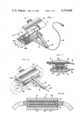
- FIG. 1 is a perspective view of a portable V-belt splicing and vulcanizing machine in accordance with the invention, shown with the upper or cover section or the machine in open position;
- FIG. 2 is a perspective view of the machine of FIG. 1 with the upper or cover section of the machine in closed position, and with a loop of the V-belt material shown in phantom in the machine for the vulcanizing operation;
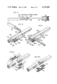
- FIG. 3 is a diagrammatic view showing the method of cutting a predetermined length of the belting from the supply of V-belt material, preparatory to forming the V-belt in the machine of FIGS. 1 and 2;
- FIG. 4 is a perspective view showing the method of cutting the required length of V-belt material, showing the belt channel which holds the V-belt material during the cutting operation, and the cutting tool which is used in making the cut;
- FIG. 5 is a perspective view showing the method of cutting the slots in the free ends of the length of V-belt material for receiving the fiber webs which join the free ends to form the splice between the free ends;
- FIG. 6 is a perspective exploded view showing the two free ends of the length of V-belt material having the slots in each end for receiving the joining or splicing fiber webs, showing the fiber webs which are received in the slots of the two free ends to form the splice between the free ends, and also showing the reinforcing strap which is secured to the outer surface of the two abutting ends of the belt to reinforce the joint;
- FIG. 6a is a fragmentary exploded view generally similar to FIG. 6 but showing a modified form of V-belt loop which does not use the reinforcing strap secured to the outer surface of the two abutting ends of the belt;
- FIG. 7 is a view in transverse section of the V-belt splicing and vulcanizing machine taken along line 7--7 of FIG. 2;
- FIG. 8 is a view in longitudinal section of the V-belt splicing and vulcanizing machine taken along line 8--8 of FIG. 7.
- the portable vulcanizing and splicing machine for V-belts is generally indicated at 10 and comprises a pair of hingedly mounted lower and upper sections respectively generally indicated at 12 and 14.
- the respective lower and upper sections 12 and 14 are provided with support arms 16 and 18 respectively.
- Lower section 12 includes a base member 20 at the outer end of the lower support arm 16; and upper section 14 includes a head or cover member 22 which lies at the outer end of upper support arm 18.
- the respective lower and upper handle members 16 and 18 are connected to the corresponding base member 20 and to head or cover member 22 substantially at the midpoint of the length of the respective members 20 and 22.
- the two support arms 16 and 18 are hingedly connected together by a hinge generally indicated at 23 and defined by cooperating hinge elements which are secured to the respective handle members 16 and 18.
- Support arms 16, 18 may be made of a suitable plastic or other suitable material, with the handles preferably having a heavy rubberized coating thereon to provide a suitable electrical and thermal insulation.
- the forward end of cover 19 is provided with a handle 19 to permit raising or lowering cover 22 about the axis of hinge 23.
- the upper surface of 20A of lower base member 20 is provided with a pair of parallel laterally spaced guide members indicated at 24A and 24B, respectively, which extend for substantially the entire length of the upper surface 20A.
- Each of the respective guide members 24A, 24B is provided with a laterally inwardly facing portion of L-shaped cross section, the two portions of L-shaped cross-section defining laterally spaced guide slots adapted to slidably receive the belt channel member generally indicated at 26 (FIG. 2), which serves as a combined cutting guide and vulcanizing mold for the V-belting which is to be formed into the fan belt or the like.
- the upper surface 20A of base member 20 is provided with a plurality of electrical contact points 28 which are adapted to cooperate with a corresponding electrical contact points 30 in the bottom surface 32A of base 32 of belt channel 26 to provide electrical energization of heating elements (not shown) in the vertical walls of belt channel 26 for vulcanization of the spliced joint between the free ends of the V-belt.
- Cover member 22 of the apparatus 10 is also provided with heating elements which provide heat for the vulcanizing operation. The heating elements of apparatus 10 are connected to electrical power through an electrical connection cord 66.
- the belt channel member generally indicated at 26 comprises a normally horizontal base portion 32.
- Belt channel 26 also comprises a pair of diverging walls 34A and 34B which are adapted to receive the V-belt therebetween during the cutting and vulcanizing operations to be described hereinafter.
- the lower end of each of the diverging walls 34A, 34B extends upwardly from a location which lies laterally inwardly of the respective parallel outer longitudinal edges of base member 32, whereby to define oppositely disposed flange portions 32-1 and 32-2, respectively, of the base member 32 which are adapted to slidably engage guide members 24A and 24B carried by the upper surface 20A of base member 20 of lower section 12 of the splicing and vulcanizing machine 10.
- each of the respective diverging walls, 34A, 34B of belt channel 26 is provided with a corresponding cross-cut 36A, 36B, the two cross-cuts 36A, 36B lying in a common plane with each other transverse of the longitudinal axis of belt channel 26, whereby to define in effect a "miter-box" which permits cutting of the belt material from a roll supply of V-belting to a proper length for formation into a V-belt loop of predetermined length, as well be explained more fully hereinafter.
- each of the respective belt channel walls 34A, 34B is provided with a pair of vertically spaced longitudinally extending slots respectively indicated at 34A-1 and 34A-2 in the case of the wall 34A; and at 34B-1 and 34B-2 in the case of belt channel sidewall 34B.
- Each of the respective slots 34A-1, 34A-2, 34B-1, and 34B-2 extends inwardly longitudinally from the outer end of the respective diverging sidewall 34A or 34B, as the case may be.
- the longitudinally-extending slots 34A-1, 34A-2, 34B-1, 34B-2 just described are adapted to receive the edge of a saw-like cutting member 60 (FIG. 5) which is used to make slots in each of the free ends of the V-belt prior to its being joined by vulcanizing to receive insert joining or splicing fiber webs which bridge the joing between the two free ends of the V-belt which is being formed into a fan belt, drive belt, or the like.
- Belt channel member 26 comes in different cross-sectional sizes to receive V-belts of different cross-sectional areas, but due to the laterally inward spacing of the lower ends of the diverging side walls 34A, 34B relative to base member 26 of belt channel member 26 and the opposite flange portions 32-1 and 32-2 thereby provided on base member 32, different belt channels 26 adapted to receive V-belts of different transverse cross-sectional dimensions can be interchangeably received in the same guide members 24A, 24B of base member 20.
- the first step in making a V-belt is to pay out from reel 68 a predetermined required length "X" of the V-belt 70 as shown in FIG. 3, the distance X being measured lengthwise from the aligned slots 36A, 36B of belt channel 26.
- the V-belt 70 is made with a substantial content of rubber or of rubber-like material, whereby the free ends of the length "X" of the V-belt are adapted to be joined in a vulcanizing operation, as will be described hereinafter.
- the knife 50 of FIG. 4 is then used to make a cross-cut transverse of the longitudinal axis of the belting to cut off the required length X of belting for fabrication into a V-belt having a loop of the required length.
- one free end of the length of V-belt which has been cut is oriented in belt channel 26 with the end surface thereof flush with the outer end of channel 26 contiguous the slots 34A-1, 34A-2, 34B-1, 34B-2.
- the saw-like cutting member 60 is then inserted first in one pair of opposite guide slots, such as the upper guide slots 34A-2 and 34B-2 at opposite lateral sides of belt channel 26, and cutting member 60 is moved along the length of guide slots 34A-2 and 34B-2 with a sawing action, the teeth 63 of the saw-like member removing the material from the belting to form a slot extending for the entire laterial width of the V-belt and for a longitudinal distance corresponding to the longitudinal length of the guide slots 34A-2, 34B-2, etc.
- the cutting member is also inserted in the other pair of guide slots, namely, the lower guide slots 34A-1 and 34B-1 at opposite lateral sides of the belt channel, cutting member 60 being operated with a sawing action in the manner previously described to form a slot for receiving lower splice element 62.
- a slot is thus produced in the upper or wider portion of the V-belt and also in the narrower or lower portion of the V-belt.
- Two splice elements are provided, including a lower splice element 62 and an upper splice element 64.
- Splice elements 62 and 64 are preferably formed of a material such as nylon fibers having a rubber-like or elastomeric material bonded to the surfaces thereof. Due to the tapered cross-section of the V-belt, the lateral width of the lower splice element 62 is less than that of the upper splice element 64. However, both splice elements 62 and 64 are of equal length in the direction of the longitudinal axis of the V-belt.
- the laterally narrower splice element 62 is inserted into bridging relation to the two slots at the lower portion of the respective abutting free ends of the V-belt; and, similarly, the laterally wider second splice element 64 is inserted into bridging relation to the longitudinal slots of the two facing and abutting free ends of the V-belt at the upper ends of the facing ends of the V-belt.
- the various cutting operations which are performed on the free ends of the V-belt, including the transverse cut through the quide slots 36A, 36B, and also the cutting operation shown in FIG. 5 which provides the longitudinal slots which receive the splice elements 62, 64 at the respective free ends of the V-belt may all preferably be performed with the belt channel 26 positioned in the guide members 24A, 24B of base member 20 of the splicing and vulcanizing machine 12.
- the transverse cut and the longitudinal cuts just described can be performed with the belt channel 26 removed from the splicing and vulcanizing machine 12, and before belt channel 26 is inserted into guide members 24A, 24B.
- the splice elements 62 and 64 may be inserted in the two free ends with the V-belt removed from belt channel 26, and then to reposition the V-belt into the belt channel 26 for the vulcanizing operation.
- the spliced connection between the two free ends of the V-belt is reinforced and strengthened by the use of a strap element 70 made of nylon or other suitable material which is secured to the corresponding outer surface of the two free ends in bridging relation thereto in the joint region.
- the strap element 70 is suitably secured to the V-belt by nails 72 or the like which extend into the belting and through the web-like splice elements 62, 64 which bridge the abutting free ends of the belting.
- the nails 72 may be made of a suitable material such as rigid nylon or metal.
- Nails 72 are preferably provided with serrated portions 74 which provide a strong connection between the nails and the material of the belting and of the web-like splices 62, 64, and which also resist removal of the nails.
- the V-belt loop is vulcanized with the strap member 70 secured to the free ends of the loop and during the vulcanizing step the strap member 70 becomes bonded to the V-belting.
- FIG. 6A a modified embodiment of a V-belt loop which is similar to the V-belt loop shown in FIG. 6 but omits the use of the bridging strap 70 shown in the preferred form of FIG. 6.
- the V-belt loop shown in FIG. 6A is formed in the same way as the loop shown in FIG. 6 except for the omission of strap 70.
- the V-belt loop is positioned in belt channel 26 which, at this time, should already be positioned in engagement with guide members 24A, 24B of the base member 20 of the lower portion of machine 10.
- the cover or head member 22 of the splicing and vulcanizing machine is closed into covering relation to the base portion 20 and to the abutting free ends of the V-belt positioned in belt channel 26.
- the heat provided by the heating elements in belt channel 26 and in cover member 22 serves to vulcanize the two free ends of the V-belt with the splice elements 62, 64 therebetween, and with the strap member 70 secured thereto.
- the amount of the heat provided for the vulcanizing operation and the length of the vulcanizing operation are so adjusted as to provide the necessary vulcanization to provide a strong joint between the two spliced ends of the V-belt.
- the various features just described provide a satisfactory splicing and bonding operation between the two spliced ends of the V-belt with respect to each other and with respect to each other and with trespect to the splice elements 62, 64 and strap element 70 which bridge the two ends of the V-belt at the splice region.
Landscapes
- Engineering & Computer Science (AREA)
- Mechanical Engineering (AREA)
- General Engineering & Computer Science (AREA)
- Chemical & Material Sciences (AREA)
- Chemical Kinetics & Catalysis (AREA)
- General Chemical & Material Sciences (AREA)
- Life Sciences & Earth Sciences (AREA)
- Forests & Forestry (AREA)
- Lining Or Joining Of Plastics Or The Like (AREA)
- Belt Conveyors (AREA)
Abstract
Description
Claims (16)
Priority Applications (1)
| Application Number | Priority Date | Filing Date | Title |
|---|---|---|---|
| US06/328,338 US4376668A (en) | 1981-12-07 | 1981-12-07 | Apparatus for and method of making V-belts |
Applications Claiming Priority (1)
| Application Number | Priority Date | Filing Date | Title |
|---|---|---|---|
| US06/328,338 US4376668A (en) | 1981-12-07 | 1981-12-07 | Apparatus for and method of making V-belts |
Publications (1)
| Publication Number | Publication Date |
|---|---|
| US4376668A true US4376668A (en) | 1983-03-15 |
Family
ID=23280576
Family Applications (1)
| Application Number | Title | Priority Date | Filing Date |
|---|---|---|---|
| US06/328,338 Expired - Fee Related US4376668A (en) | 1981-12-07 | 1981-12-07 | Apparatus for and method of making V-belts |
Country Status (1)
| Country | Link |
|---|---|
| US (1) | US4376668A (en) |
Cited By (8)
| Publication number | Priority date | Publication date | Assignee | Title |
|---|---|---|---|---|
| US4416027A (en) * | 1983-01-31 | 1983-11-22 | Perla Henry L | Diving suit seam construction |
| WO1986003454A1 (en) * | 1984-12-06 | 1986-06-19 | Belt Repair Kits, Inc. | Pulley belt kit and method of use |
| US4671834A (en) * | 1985-05-23 | 1987-06-09 | Price John G | Method of splicing belt |
| US5294273A (en) * | 1993-03-03 | 1994-03-15 | Tripp Benjamin A | Method of making a composite belt from used tires |
| US5650210A (en) * | 1993-03-25 | 1997-07-22 | Forestry And Forest Products Research Institute | Wood joining structure and method thereof |
| EP1518816A3 (en) * | 2003-09-25 | 2006-12-13 | New-York Hamburger Gummi-Waaren Compagnie AG | Method and device for endless interlocking of the handrail of a moving walkway or escalator |
| EP3106286A1 (en) * | 2015-06-16 | 2016-12-21 | The Goodyear Tire & Rubber Company | Method of securing splices in curable rubber articles |
| CN111093927A (en) * | 2017-09-11 | 2020-05-01 | 日本中田工程株式会社 | Connecting roller and conveying device |
Citations (6)
| Publication number | Priority date | Publication date | Assignee | Title |
|---|---|---|---|---|
| US2718255A (en) * | 1953-06-29 | 1955-09-20 | Louis Levin & Son Inc | Belt splicing device |
| US2778420A (en) * | 1954-04-14 | 1957-01-22 | Robins Industries Corp | Tape splicing device |
| US3101290A (en) * | 1957-04-01 | 1963-08-20 | Pneumatiques & Caoutchous Manu | Method of joining the ends of a multi-ply laminated belt |
| US3546054A (en) * | 1968-06-20 | 1970-12-08 | William H Ross | Spliced conveyor belt and method of making same |
| US3895990A (en) * | 1971-07-30 | 1975-07-22 | Rheinische Braunkohlenw Ag | Process for joining strips of belt along their lengthwise running side edges |
| US4207135A (en) * | 1977-06-24 | 1980-06-10 | P.E.P. Associates | Kit apparatus for making O-rings |
-
1981
- 1981-12-07 US US06/328,338 patent/US4376668A/en not_active Expired - Fee Related
Patent Citations (6)
| Publication number | Priority date | Publication date | Assignee | Title |
|---|---|---|---|---|
| US2718255A (en) * | 1953-06-29 | 1955-09-20 | Louis Levin & Son Inc | Belt splicing device |
| US2778420A (en) * | 1954-04-14 | 1957-01-22 | Robins Industries Corp | Tape splicing device |
| US3101290A (en) * | 1957-04-01 | 1963-08-20 | Pneumatiques & Caoutchous Manu | Method of joining the ends of a multi-ply laminated belt |
| US3546054A (en) * | 1968-06-20 | 1970-12-08 | William H Ross | Spliced conveyor belt and method of making same |
| US3895990A (en) * | 1971-07-30 | 1975-07-22 | Rheinische Braunkohlenw Ag | Process for joining strips of belt along their lengthwise running side edges |
| US4207135A (en) * | 1977-06-24 | 1980-06-10 | P.E.P. Associates | Kit apparatus for making O-rings |
Cited By (9)
| Publication number | Priority date | Publication date | Assignee | Title |
|---|---|---|---|---|
| US4416027A (en) * | 1983-01-31 | 1983-11-22 | Perla Henry L | Diving suit seam construction |
| WO1986003454A1 (en) * | 1984-12-06 | 1986-06-19 | Belt Repair Kits, Inc. | Pulley belt kit and method of use |
| US4671834A (en) * | 1985-05-23 | 1987-06-09 | Price John G | Method of splicing belt |
| US5294273A (en) * | 1993-03-03 | 1994-03-15 | Tripp Benjamin A | Method of making a composite belt from used tires |
| US5650210A (en) * | 1993-03-25 | 1997-07-22 | Forestry And Forest Products Research Institute | Wood joining structure and method thereof |
| EP1518816A3 (en) * | 2003-09-25 | 2006-12-13 | New-York Hamburger Gummi-Waaren Compagnie AG | Method and device for endless interlocking of the handrail of a moving walkway or escalator |
| EP3106286A1 (en) * | 2015-06-16 | 2016-12-21 | The Goodyear Tire & Rubber Company | Method of securing splices in curable rubber articles |
| CN111093927A (en) * | 2017-09-11 | 2020-05-01 | 日本中田工程株式会社 | Connecting roller and conveying device |
| CN111093927B (en) * | 2017-09-11 | 2022-04-05 | 日本中田工程株式会社 | Connecting roller and conveying device |
Similar Documents
| Publication | Publication Date | Title |
|---|---|---|
| US4376668A (en) | Apparatus for and method of making V-belts | |
| CA1286978C (en) | Belt skiving method and apparatus | |
| US4315450A (en) | Method of and apparatus for sciving belts | |
| US20020092889A1 (en) | Friction stir welding method, and method for manufacturing car body | |
| US4618387A (en) | Splicing methods for an extruded handrail | |
| US4350066A (en) | Cove molding cutting apparatus and attachment | |
| EP0324199A1 (en) | A cutting device for cutting a strip of unvulcanized rubber | |
| US4904319A (en) | Method of ultrasonic splicing tire tread strip edges | |
| MX2013012625A (en) | Methods and apparatus for joining treads. | |
| US6675853B2 (en) | Apparatus for forming a splice joint for plastic coated fabric conveyor belt | |
| US6119752A (en) | Tool for welding plastic members | |
| US6062122A (en) | Cutting guide system for portable power saws | |
| US4547954A (en) | Extrusion cladding of base strip for cushioned automotive strap handle | |
| EP0172605A1 (en) | Method for splicing of elastomeric belts | |
| US4082592A (en) | Splicing of tread strips | |
| US4741235A (en) | Apparatus for splicing belt | |
| US4671834A (en) | Method of splicing belt | |
| EP0933555B1 (en) | Conveyor belt joint | |
| US5001958A (en) | Apparatus for preparing skived belting | |
| CN113210744A (en) | Steel plate cutting device and steel plate cutting method thereof | |
| US4212213A (en) | Web severing device and process for severing a web | |
| US6195903B1 (en) | Tools for squaring ends of elongated objects | |
| EP0460792A2 (en) | Metal reinforcements for sealing strips and the like and methods of making them | |
| CN217372134U (en) | Carry platform frock clamp | |
| WO2000034040A1 (en) | Waterstop joining tool |
Legal Events
| Date | Code | Title | Description |
|---|---|---|---|
| AS | Assignment |
Owner name: HUNT, EARLENE Free format text: ASSIGNMENT OF ASSIGNORS INTEREST.;ASSIGNOR:GINTER, THOMAS JR.;REEL/FRAME:004617/0627 Effective date: 19860505 Owner name: HUNT, HAROLD E., Free format text: ASSIGNMENT OF ASSIGNORS INTEREST.;ASSIGNOR:GINTER, THOMAS JR.;REEL/FRAME:004617/0627 Effective date: 19860505 |
|
| FEPP | Fee payment procedure |
Free format text: MAINTENANCE FEE REMINDER MAILED (ORIGINAL EVENT CODE: REM.); ENTITY STATUS OF PATENT OWNER: SMALL ENTITY |
|
| LAPS | Lapse for failure to pay maintenance fees | ||
| STCH | Information on status: patent discontinuation |
Free format text: PATENT EXPIRED DUE TO NONPAYMENT OF MAINTENANCE FEES UNDER 37 CFR 1.362 |
|
| FP | Lapsed due to failure to pay maintenance fee |
Effective date: 19870315 |