US4370296A - Toroidal fusion reactor having ohmic heating coil substantially adjacent toroidal fusion region - Google Patents
Toroidal fusion reactor having ohmic heating coil substantially adjacent toroidal fusion region Download PDFInfo
- Publication number
- US4370296A US4370296A US06/157,347 US15734780A US4370296A US 4370296 A US4370296 A US 4370296A US 15734780 A US15734780 A US 15734780A US 4370296 A US4370296 A US 4370296A
- Authority
- US
- United States
- Prior art keywords
- toroidal
- fusion
- region
- coils
- main axis
- Prior art date
- Legal status (The legal status is an assumption and is not a legal conclusion. Google has not performed a legal analysis and makes no representation as to the accuracy of the status listed.)
- Expired - Lifetime
Links
- 230000004927 fusion Effects 0.000 title claims abstract description 111
- 238000010438 heat treatment Methods 0.000 title claims abstract description 30
- 238000006243 chemical reaction Methods 0.000 claims abstract description 16
- 239000000463 material Substances 0.000 claims description 26
- 230000004992 fission Effects 0.000 claims description 19
- 238000000034 method Methods 0.000 claims description 4
- 238000013461 design Methods 0.000 description 17
- 238000001816 cooling Methods 0.000 description 13
- 238000009395 breeding Methods 0.000 description 8
- 230000001488 breeding effect Effects 0.000 description 8
- 239000010949 copper Substances 0.000 description 6
- 238000010586 diagram Methods 0.000 description 6
- 238000004519 manufacturing process Methods 0.000 description 6
- YZCKVEUIGOORGS-NJFSPNSNSA-N Tritium Chemical compound [3H] YZCKVEUIGOORGS-NJFSPNSNSA-N 0.000 description 5
- 229910052770 Uranium Inorganic materials 0.000 description 5
- 229910052722 tritium Inorganic materials 0.000 description 5
- JFALSRSLKYAFGM-UHFFFAOYSA-N uranium(0) Chemical compound [U] JFALSRSLKYAFGM-UHFFFAOYSA-N 0.000 description 5
- XKRFYHLGVUSROY-UHFFFAOYSA-N Argon Chemical compound [Ar] XKRFYHLGVUSROY-UHFFFAOYSA-N 0.000 description 4
- WHXSMMKQMYFTQS-UHFFFAOYSA-N Lithium Chemical compound [Li] WHXSMMKQMYFTQS-UHFFFAOYSA-N 0.000 description 4
- 238000005253 cladding Methods 0.000 description 4
- 229910052744 lithium Inorganic materials 0.000 description 4
- RYGMFSIKBFXOCR-UHFFFAOYSA-N Copper Chemical compound [Cu] RYGMFSIKBFXOCR-UHFFFAOYSA-N 0.000 description 3
- 229910052802 copper Inorganic materials 0.000 description 3
- 230000008878 coupling Effects 0.000 description 3
- 238000010168 coupling process Methods 0.000 description 3
- 238000005859 coupling reaction Methods 0.000 description 3
- 239000000203 mixture Substances 0.000 description 3
- YZCKVEUIGOORGS-OUBTZVSYSA-N Deuterium Chemical compound [2H] YZCKVEUIGOORGS-OUBTZVSYSA-N 0.000 description 2
- 229910000711 U alloy Inorganic materials 0.000 description 2
- 229910052786 argon Inorganic materials 0.000 description 2
- 230000008901 benefit Effects 0.000 description 2
- 238000004891 communication Methods 0.000 description 2
- 239000002826 coolant Substances 0.000 description 2
- 229910052805 deuterium Inorganic materials 0.000 description 2
- 239000012530 fluid Substances 0.000 description 2
- 230000004907 flux Effects 0.000 description 2
- 239000000446 fuel Substances 0.000 description 2
- 238000012986 modification Methods 0.000 description 2
- 230000004048 modification Effects 0.000 description 2
- KTEXACXVPZFITO-UHFFFAOYSA-N molybdenum uranium Chemical compound [Mo].[U] KTEXACXVPZFITO-UHFFFAOYSA-N 0.000 description 2
- 230000005855 radiation Effects 0.000 description 2
- 238000012552 review Methods 0.000 description 2
- 239000010935 stainless steel Substances 0.000 description 2
- 229910001220 stainless steel Inorganic materials 0.000 description 2
- OKTJSMMVPCPJKN-UHFFFAOYSA-N Carbon Chemical compound [C] OKTJSMMVPCPJKN-UHFFFAOYSA-N 0.000 description 1
- QCWXUUIWCKQGHC-UHFFFAOYSA-N Zirconium Chemical compound [Zr] QCWXUUIWCKQGHC-UHFFFAOYSA-N 0.000 description 1
- 229910001093 Zr alloy Inorganic materials 0.000 description 1
- 239000011248 coating agent Substances 0.000 description 1
- 238000000576 coating method Methods 0.000 description 1
- 238000002474 experimental method Methods 0.000 description 1
- 230000002349 favourable effect Effects 0.000 description 1
- 239000012634 fragment Substances 0.000 description 1
- 239000007789 gas Substances 0.000 description 1
- 229910002804 graphite Inorganic materials 0.000 description 1
- 239000010439 graphite Substances 0.000 description 1
- 229910052751 metal Inorganic materials 0.000 description 1
- 239000002184 metal Substances 0.000 description 1
- 150000002739 metals Chemical class 0.000 description 1
- 238000005457 optimization Methods 0.000 description 1
- 230000009467 reduction Effects 0.000 description 1
- NBWXXYPQEPQUSB-UHFFFAOYSA-N uranium zirconium Chemical compound [Zr].[Zr].[U] NBWXXYPQEPQUSB-UHFFFAOYSA-N 0.000 description 1
- 229910052726 zirconium Inorganic materials 0.000 description 1
Images


Classifications
-
- H—ELECTRICITY
- H05—ELECTRIC TECHNIQUES NOT OTHERWISE PROVIDED FOR
- H05H—PLASMA TECHNIQUE; PRODUCTION OF ACCELERATED ELECTRICALLY-CHARGED PARTICLES OR OF NEUTRONS; PRODUCTION OR ACCELERATION OF NEUTRAL MOLECULAR OR ATOMIC BEAMS
- H05H1/00—Generating plasma; Handling plasma
- H05H1/02—Arrangements for confining plasma by electric or magnetic fields; Arrangements for heating plasma
- H05H1/10—Arrangements for confining plasma by electric or magnetic fields; Arrangements for heating plasma using externally-applied magnetic fields only, e.g. Q-machines, Yin-Yang, base-ball
- H05H1/12—Arrangements for confining plasma by electric or magnetic fields; Arrangements for heating plasma using externally-applied magnetic fields only, e.g. Q-machines, Yin-Yang, base-ball wherein the containment vessel forms a closed or nearly closed loop
-
- G—PHYSICS
- G21—NUCLEAR PHYSICS; NUCLEAR ENGINEERING
- G21B—FUSION REACTORS
- G21B1/00—Thermonuclear fusion reactors
- G21B1/01—Hybrid fission-fusion nuclear reactors
-
- Y—GENERAL TAGGING OF NEW TECHNOLOGICAL DEVELOPMENTS; GENERAL TAGGING OF CROSS-SECTIONAL TECHNOLOGIES SPANNING OVER SEVERAL SECTIONS OF THE IPC; TECHNICAL SUBJECTS COVERED BY FORMER USPC CROSS-REFERENCE ART COLLECTIONS [XRACs] AND DIGESTS
- Y02—TECHNOLOGIES OR APPLICATIONS FOR MITIGATION OR ADAPTATION AGAINST CLIMATE CHANGE
- Y02E—REDUCTION OF GREENHOUSE GAS [GHG] EMISSIONS, RELATED TO ENERGY GENERATION, TRANSMISSION OR DISTRIBUTION
- Y02E30/00—Energy generation of nuclear origin
- Y02E30/10—Nuclear fusion reactors
Definitions
- the invention is in the field of fusion reactor designs and particularly relates to ohmic heating coils for toroidal-type fusion reactors.
- the invention is also applicable to fusion-fission hybrid type reactors.
- the ohmic heating coil takes the form of a transformer positioned in the center of the toroidal configuration as illustrated, for example, in U.S. Pat. No. 3,778,343.
- Yet another object of the invention is to provide a more efficient ohmic heating coupling to the plasma region of a fusion device of the toroidal-type.
- a further object of the invention is to provide a more efficient ohmic heating coupling for fusion-fission type reactors or power generating devices.
- a fusion reactor of the toroidal-type having a plasma containing toroidal fusion region for producing energy from fusion reactions.
- the fusion reactor comprises toroidal field generating means for producing a toroidal magnetic field in the plasma fusion region upon the passage of current therethrough.
- the toroidal field generating means is positioned proximate the toroidal fusion region.
- Ohmic heating coils are provided for ohmically heating the plasma within the plasma fusion region, and the ohmic heating coils are positioned between the fusion region and the toroidal field generating means on the side nearest the main axis of the toroidal fusion region.
- a method of increasing efficiency of a fusion reactor of a toroidal configuration having toroidal field coils positioned substantially adjacent a toroidal fusion region and ohmic heating coils for ohmically heating plasma within the toroidal fusion region.
- the method comprises the step of positioning the ohmic heating coils between the toroidal fusion region and the toroidal field coils on a side nearest the main axis of the toroidal fusion region.
- a fusion power generating means comprising a fusion power core having a toroidal fusion region, a toroidal field generating means positioned proximate the toroidal fusion region and an ohmic heating means positioned between the toroidal fusion region and the toroidal generating means.
- the power generating means comprises means for extracting thermal energy from the fusion power core and is constructed such that the fusion power core is removable from the power generating means for replacement thereof by a replacement fusion power core.
- FIG. 1 is a block schematic diagram of prior art reactors
- FIGS. 2A and 2B show block schematic diagrams of embodiments of the invention
- FIG. 3 is a block schematic diagram of yet another embodiment of the invention.
- FIG. 4 is a block schematic diagram of a power generating device in accordance with the principles of the invention.
- FIG. 5 is a partial plan view of the major components of the reactor in accordance with the principles of the invention.
- FIG. 6 is a side view of a toroidal field sector made in accordance with the invention.
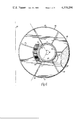
- FIG. 7 is a perspective view of a toroidal field sector.
- FIG. 1 is a block diagram of prior art toroidal-type fusion-fission reactor designs. The figure illustrates a cross-sectional representative view of the toroid which is symmetric about a major axis 24.
- a toroidal fusion region 4 is provided for housing the fusion fuel which may be, for example, a mixture of deuterium and tritium.
- a fission blanket 6 Surrounding the fusion region 4 is a fission blanket 6 which contains fissionable material such as natural uranium (U 238 ) or a uranium alloy.
- a moderator/reflector region 8 is also provided around the fission blanket 6 to slow down fast neutrons produced in both the fusion and fission regions and to reflect these neutrons as low energy neutrons back into the fission blanket 6.
- the resulting thermal neutrons within the fission blanket do not induce fission reactions in U 238 but rather are captured and lead to the production of fissile material, namely, Pu 239 .
- a T breeding section 10 which comprises lithium utilized to breed tritium via thermal and/or fast neutron capture. The tritium may then be utilized to replace tritium consumed by the d,t fusion reaction.
- Surrounding the T breeding section 10 is a shielding area 12.
- Toroidal field (TF) coils 14 surround and are protected by the shielding area 12 and are utilized to generate a toroidal field within the fusion region 4.
- Ohmic heating (OH) coils 16 are also illustrated adjacent the toroidal field coils 14 and are utilized to ohmically heat the plasma fusion region 4.
- FIG. 2a is a schematic block diagram of a toroidal fusion device similar to FIG. 1 but illustrating the novel structural arrangement in accordance with the principles of the invention.
- a fusion-fission reactor 20 is illustrated comprising a fusion region 22 which is typically in the form of a toroid having a main axis 24.
- a plurality of toroidal field coils 24' are provided which have incorporated within a region thereof the fissile-fertile material 26.
- the fissile-fertile material 26 may, of example, comprise natural uranium, a uranium-molybdenum or uranium-zirconium alloy or the like.
- the fissile-fertile material is fissionable with respect to high energy neutrons produced from the fusion reaction and is fertile with respect to low energy neutrons thus producing additional fissile material.
- the particular structure of the toroidal field coils 24' and the fissile-fertile material 26 is described more fully below and may typically comprise an integral structure positioned substantially adjacent the fusion region 22 with only a vacuum vessel (and associated cooling panels) therebetween to house the plasma and cool the vacuum vessel first wall.
- a containment means 28 Surrounding the toroidal field coils 24' and fissile-fertile material 26 is a containment means 28 for housing the toroidal field coils 24'.
- the containment means 28 may be fabricated from stainless steel, copper or other metals and is provided with an insulative coating to prevent shorting of the TF coils.
- the ohmic heating (OH) coils 36 are also provided within the containment means 28. Provisions are made for connecting the OH and TF coils to appropriate power supplies as is well known in the art.
- a moderator/reflector region 30, fabricated from graphite, for example, is also provided exterior to the containment means, and a T breeding section (lithium) 32 is positioned exterior of the moderator/reflector region 30.
- a shielding area 34 is also provided around the T breeding section 32.
- FIG. 2B is another embodiment of the invention similar to FIG. 2A but shows the containment means 28b surrounding the TF coils 24' and fusion region 22 with the OH coils 36 outside thereof. OH coils 36 may also be enclosed in a separate containment means, not shown.
- FIG. 3 illustrates yet another embodiment of the invention which is similar to that of FIG. 2 with the exception that the OH coils 36' are now positioned within the region of the toroidal field coils generally disposed in-between the fusion area 22' and the TF coils 34'. Elements similar to those in FIG. 2 are labeled with primes.
- the embodiment of FIG. 3 essentially frees the interior of the toroidal area near the main axis 24 of the traditional bulky OH coil transformer and provides for the efficient OH heating of the fusion region 22' by positioning the OH coils substantially adjacent the fusion region 22'.
- the removal of the OH coils from the interior region of the toroid permits a more efficient design of the TF coils 24' by allowing for larger TF coil cross-sectional areas within this vicinity of the main axis 24 with substantial reduction in current densities.
- a resulting increase in TF magnetic strength is achieved which, coupled to a more efficient operation of the OH coils, enhances efficiency and stability of the operation of the fusion region 22'.
- Positioning the OH coils 36' within the region of the TF coils 24' is applicable to pure fusion toroidal-type reactors as well as the fusion-fission type.
- FIG. 4 is illustrated for the fusion-fission unit 20 of FIG. 2 although it is readily understood that a similar system could be operated with respect to the corresponding elements of FIG. 3.
- the containment means 28 together with everything contained therein, in particular, the OH coils 36, the toroidal field coils 24', the fissile-fertile material 26 and the fusion region 22, form a unit which may be identified as a fusion-fission power core (FFPC) 40.
- the FFPC core 40 is in said recessed portion.
- each of the fusion-fission reactors 20 is modular in the sense that the FFPC 40 may effectively be separated and removed from the remaining reactor elements for replacement by a replacement or substitute FFPC after the fissile-fertile material has been depleted to the extent that fission reactions no longer contribute in an optimum way to the overall energy production of the machine.
- the fusion-fission power core 40 may be replaced on the order of yearly intervals.
- FIG. 4 generally depicts the interconnection of the fusion-fission reactor to power supply means 50 and heat exchange, pumps and turbine apparatus 54.
- Power supply 50 is utilized to provide power to the OH and TF coils as well as power to auxiliary heating and equilibrium field coils (not shown) as are present in conventional Tokamak designs.
- the heat exchange, pumps and turbine apparatus 54 are generally interconnected to the fusion-fission power core 40 to extract thermal energy therefrom and simultaneously to cool the fusion-fission core during operation thereof.
- the overall interconnection of the fusion-fission power cores in a modular array to form a power generating plant may be similar to the modular fusion apparatus more fully illustrated in copending application entitled "Modular Fusion Power Apparatus Using Disposable Core", Ser. No. 841,903, incorporated herein by reference.
- FIGS. 5-7 depict the embodiment of FIG. 3 wherein the OH coils 36' are positioned interior of the toroidal field coils 24'. However, it is readily understood that the OH coils may be positioned as illustrated in FIG. 2 exterior of the TF coils as shown, for example, in the copending application referenced hereinabove.
- the structure of the toroidal field coils and the fissile-fertile material is substantially the same with the exceptions that the cut-out region for the OH coil within the TF coil structure is no longer present, and that the radial dimension of the TF coils toward the main axis of the toroid is reduced in order to allow space for the OH transformer in the region of the toroid main axis.
- FIG. 5 is a top plan view of the portion of the fusion-fission reactor 20' wherein the main axis and center of the toroid is to the left in the drawing.
- the reactor comprises a plasma containment means 100 utilized to contain the fusion plasma gas, typically a mixture of deuterium and tritium. It is understood, however, that in addition to the d,t reaction additional fusion reactions may be utilized such as D,D or D,He 3 etc.
- the plasma containment means 100 is symmetric about the main axis 102. In both FIGS. 5 and 6, however, the main axis 102 is shown closer to the plasma containment means 100 than dictated by the scale factors of the drawing in order to illustrate in clear detail the novel toroidal field structure of the invention.
- a toroidal field generating means Surrounding the plasma containment means 100 is a toroidal field generating means generally indicated at 104 which comprises a plurality of TF sectors 106 each of which comprises the toroidal field coils 108.
- the main axis of the toroid defined by TF sectors 106 will typically coincide with the main axis of the containment means 100.
- FIG. 5 illustrates the OH coils 110, containment means 112, moderator/reflector 114 and T breeding section 116.
- the modulator/reflector 114 is shown segmented to indicate that it would typically be of a size larger than illustrated and would generally be on the order of the TF coil radius.
- Particular cooling and cladding of the modulator/reflector as well as the structure of the T breeding section 116 are well known in the art and are not shown for the sake of clarity.
- the toroidal field sector 106 is seen to comprise a region of fissile-fertile material 120 such as, for example, natural uranium, or any of the uranium alloys such as uranium molybdenum, zirconium, etc.
- the fissile-fertile region within each of the TF sectors 106 is shown in the form of two separate regions namely, regions 120a and 120b, which effectively sandwich a portion of the TF coils 108 therebetween. Other arrangements are of course possible such as positioning the region 120 entirely on one side of the TF sectors 106.
- the fissile-fertile material 120 does not extend completely around the TF sector 106 but rather is disposed primarily in the region away from the main axis 102.
- FIG. 6 illustrates that the fissile-fertile material region 120 is disposed around the TF sector 106 through an angle ⁇ which may typically be on the order of 240°.
- the regions 120a and 120b optimumally extend to a region as close to the fusion region as possible to take maximum advantage of the neutron flux.
- the regions 120a and 120b extend from substantially the inner circumferential contour of the toroidal field coils 108 to substantially the outer circumferential contour thereof. These contours are shown by indicia C1 and C2 respectively.
- the regions of fissile-fertile material 120a and 120b are encased in a cladding 122 which may typically be of stainless steel wherein there is provided a plurality of cooling channels (or grooves) 124. Cooling channels 124 are likewise provided throughout the TF coils 108, a few of which channels are illustrated in FIGS. 6 and 7. Because of the close proximity of the TF coils 108 to the plasma containment means 100, the entire region of the TF coils typically contains either radial cooling channels, as illustrated, or circumferential cooling channels if desired. These channels may be spaced on the order of a centimeter apart and may typically occur both within the TF coils 108 and on the cladding 122. As best illustrated in FIG. 6, these cooling channels may also be in fluid communication with a cut-out region 130 of the TF coils 108, to thereby cool the OH coils 128 which are illustrated as being inserted within cut-out region 130.
- the toroid radius to the center of the plasma may be on the order of 50-100 cm, the plasma radius 20-50 cm, moderator/reflector region thickness 10-30 cm and the lithium T breeding section a distance from the center of the plasma on the order of 300 cm.
- the volume fraction of U 238 to Cu in the TF coils may typically be from 5-50%.
- the plasma containment region 100 although illustrated as a simple shell in practice may contain a coolant panel in fluid communication with the radial or circumferential cooling channels 124 within the TF coils 108 and cladding 122.
- the plasma containment means 100 is illustrated as having a circular cross-sectional area, it is understood that additional designs recognized in the art are also possible, such as, for example, the D configuration well known in Tokamak studies.
- the corresponding TF generating means 104 is naturally designed consistent with the shape of the plasma containment means 100.
- the TF coils 108 be positioned substantially adjacent (consistent with first wall loading and cooling requirements) to the plasma containment means 100 and additionally that the region of fissile-fertile material 120 is also positioned substantially adjacent to the plasma containment means 100. This particular arrangement allows optimization of the fusion-fission reaction and produces an extremely large burn up of the uranium fuel.
- This close proximity of the TF coil sectors 106 and the fissile-fertile region 120 to the fusion area permits a high fission-to-fusion energy production ratio on the order of 10:1.
- This high ratio of fission to fusion energy allows operation of the FFPC at gross fusion power levels significantly less than those which would be required for operation of a pure fusion power device--in particular, FFPC lifetimes, as limited by radiation damage by fusion neutrons, may be ten or more times greater for the same net nuclear energy output (fission plus fusion) than for fusion alone.
- this invention allows operation over FFPC lifetimes as high as one to two years. Over such long time periods the high fusion neutron flux will result in large burnup utilization of the U 238 in the coils, in proximity to the plasma. Indeed, calculations indicate that as much as 80% of the uranium should be fissioned in the first three centimenters of the fissile-fertile region 120 nearest the plasma containment means 100. Average burn up percentages are on the order of 50%.
- the particular composition and thickness of the moderator/reflector is selected to slow down and reflect neutrons into the fissile-fertile material at energies which optimize overall energy production of the reactor.
- the terminology "low energy neutrons" as utilized in the appended claims thus is intended to cover such neutron energies.
- epithermal neutrons are expected to have large cross sections for n capture, and known resonance peaks in U 238 extend generally in the range of 6-200 ev. Thermal neutrons will also contribute to Pu 239 production.
- An important aspect of the design of the fusion-fission reactor in accordance with the principles of the invention is in the positioning of the TF coils substantially adjacent the toroidal fusion region.
- the TF coils are positioned adjacent any such cooling region such that they are substantially adjacent to the fusion region itself.
- the positioning of the TF coils substantially adjacent the fusion region and the provision for positioning the fissile-fertile material in the region of the TF coils is a sharp contrast to prior art designs.
- fissile-fertile material within the region of the TF coils
- the fissile-fertile material typically will be a distinct region positioned within the region defined between the inner and outer circumferential contour of the TF coils.
- these coils likewise are positioned substantially adjacent the fusion region but are located on the side of the toroidal fusion region nearest the main axis thereof.
- ohmic heating means in the form of ohmic heating coils has been described hereinabove in reference to a fusion-fission reactor or power generating device, it is clear that one may utilize the invention in a pure fusion type reactor or fusion type generating means.
- the fissile-fertile material within the region of the toroidal field coils may be eliminated as well as the modular/reflector utilized to slow and reflect the high energy neutrons.
- the remaining apparatus comprises a fusion power core which includes the containment means, toroidal field coils, ohmic heating coils and fusion region.
- the fusion power core may be interconnected with means for extracting thermal energy from the fusion power core in a modular array as more fully set forth in, for example, copending application Ser. No. 841,903 cited above.
- the fusion power core may be an integral unit which is separable from the fusion power generating means and replaceable by a different fusion power core after, for example, excessive radiation damage of the TF coils.
- these coils are located substantially adjacent the fusion region on a side nearest the main axis of the toroidal fusion region.
Landscapes
- Physics & Mathematics (AREA)
- Engineering & Computer Science (AREA)
- Plasma & Fusion (AREA)
- Optics & Photonics (AREA)
- Spectroscopy & Molecular Physics (AREA)
- General Engineering & Computer Science (AREA)
- High Energy & Nuclear Physics (AREA)
- Plasma Technology (AREA)
Abstract
A fusion reactor of the toroidal-type having a plasma containing toroidal fusion region producing energy from fusion reactions and comprising a toroidal field generating means for producing a toroidal magnetic field in the fusion region upon passage of current therethrough, said toroidal field generating means positioned proximate the toroidal fusion region, and ohmic heating coils for ohmically heating the plasma wherein the ohmic heating coils are positioned between the toroidal fusion region and the toroidal field generating means.
Description
This is a continuation, of application Ser. No. 888,803, filed Mar. 21, 1978 now abandoned.
1. Field of the Invention
The invention is in the field of fusion reactor designs and particularly relates to ohmic heating coils for toroidal-type fusion reactors. The invention is also applicable to fusion-fission hybrid type reactors.
2. Description of the Prior Art
A large number of studies have been directed to the design of toroidal-type fusion reactors as well as to the design of fusion-fission reactors. Representative studies include the following: Tokamak Experimental Power Reactor Conceptual Design, Volumes I and II, Argon National Laboratory, ANL/CTR-76-3, August 1976; Proceedings US-USSR Symposium on Fusion-Fission Reactors, July 13-16, 1976; and DCTR Fusion-Fission Energy Systems Review Meeting, Dec. 3-4, 1974, ERDA-4. In typical prior art toroidal-type fusion experiments and designs, the ohmic heating coil takes the form of a transformer positioned in the center of the toroidal configuration as illustrated, for example, in U.S. Pat. No. 3,778,343. It has long been desired to decrease the size of this OH transformer, particularly in view of the rather stringent space requirements present in existing machines. Attempts have been made, for example, to specifically design the toroidal field coils surrounding the plasma region to optimize space requirements within the toroidal region center along the main axis of the toroid. Such studies are exemplified by U.S. Pat. No. 3,859,615. The ability to utilize the interior space of a toroid would greatly relax the stringent design requirements imposed on toroidal-type fusion reactors and permit the utilization of lower current densities within the TF coils.
Accordingly, it is an object of the invention to increase the operating efficiency of toroidal-type fusion reactors.
It is a further object of the invention to remove the ohmic heating transformer from the region of the main axis of the toroidal field coils to thereby enable radial expansion of the TF coil cross-sectional area within the region of the main axis.
Yet another object of the invention is to provide a more efficient ohmic heating coupling to the plasma region of a fusion device of the toroidal-type.
A further object of the invention is to provide a more efficient ohmic heating coupling for fusion-fission type reactors or power generating devices.
In accordance with the principles of the invention there is provided a fusion reactor of the toroidal-type having a plasma containing toroidal fusion region for producing energy from fusion reactions. The fusion reactor comprises toroidal field generating means for producing a toroidal magnetic field in the plasma fusion region upon the passage of current therethrough. The toroidal field generating means is positioned proximate the toroidal fusion region. Ohmic heating coils are provided for ohmically heating the plasma within the plasma fusion region, and the ohmic heating coils are positioned between the fusion region and the toroidal field generating means on the side nearest the main axis of the toroidal fusion region.
There is also disclosed in accordance with the principles of the invention a method of increasing efficiency of a fusion reactor of a toroidal configuration having toroidal field coils positioned substantially adjacent a toroidal fusion region and ohmic heating coils for ohmically heating plasma within the toroidal fusion region. The method comprises the step of positioning the ohmic heating coils between the toroidal fusion region and the toroidal field coils on a side nearest the main axis of the toroidal fusion region.
There is also disclosed in accordance with the principles of the invention a fusion power generating means comprising a fusion power core having a toroidal fusion region, a toroidal field generating means positioned proximate the toroidal fusion region and an ohmic heating means positioned between the toroidal fusion region and the toroidal generating means. Further, the power generating means comprises means for extracting thermal energy from the fusion power core and is constructed such that the fusion power core is removable from the power generating means for replacement thereof by a replacement fusion power core.
These and other objects of the invention will become apparent in reference to the specification and drawings wherein:
FIG. 1 is a block schematic diagram of prior art reactors;
FIGS. 2A and 2B show block schematic diagrams of embodiments of the invention;
FIG. 3 is a block schematic diagram of yet another embodiment of the invention;
FIG. 4 is a block schematic diagram of a power generating device in accordance with the principles of the invention;
FIG. 5 is a partial plan view of the major components of the reactor in accordance with the principles of the invention;
FIG. 6 is a side view of a toroidal field sector made in accordance with the invention; and
FIG. 7 is a perspective view of a toroidal field sector.
FIG. 1 is a block diagram of prior art toroidal-type fusion-fission reactor designs. The figure illustrates a cross-sectional representative view of the toroid which is symmetric about a major axis 24. Typically, a toroidal fusion region 4 is provided for housing the fusion fuel which may be, for example, a mixture of deuterium and tritium. Surrounding the fusion region 4 is a fission blanket 6 which contains fissionable material such as natural uranium (U238) or a uranium alloy. A moderator/reflector region 8 is also provided around the fission blanket 6 to slow down fast neutrons produced in both the fusion and fission regions and to reflect these neutrons as low energy neutrons back into the fission blanket 6. The resulting thermal neutrons within the fission blanket do not induce fission reactions in U238 but rather are captured and lead to the production of fissile material, namely, Pu239. After the moderator/reflector region 8 there is generally provided a T breeding section 10 which comprises lithium utilized to breed tritium via thermal and/or fast neutron capture. The tritium may then be utilized to replace tritium consumed by the d,t fusion reaction. Surrounding the T breeding section 10 is a shielding area 12. Toroidal field (TF) coils 14 surround and are protected by the shielding area 12 and are utilized to generate a toroidal field within the fusion region 4. Ohmic heating (OH) coils 16 are also illustrated adjacent the toroidal field coils 14 and are utilized to ohmically heat the plasma fusion region 4.
FIG. 2a is a schematic block diagram of a toroidal fusion device similar to FIG. 1 but illustrating the novel structural arrangement in accordance with the principles of the invention. Accordingly, a fusion-fission reactor 20 is illustrated comprising a fusion region 22 which is typically in the form of a toroid having a main axis 24. A plurality of toroidal field coils 24' are provided which have incorporated within a region thereof the fissile-fertile material 26. The fissile-fertile material 26, may, of example, comprise natural uranium, a uranium-molybdenum or uranium-zirconium alloy or the like. The fissile-fertile material is fissionable with respect to high energy neutrons produced from the fusion reaction and is fertile with respect to low energy neutrons thus producing additional fissile material. The particular structure of the toroidal field coils 24' and the fissile-fertile material 26 is described more fully below and may typically comprise an integral structure positioned substantially adjacent the fusion region 22 with only a vacuum vessel (and associated cooling panels) therebetween to house the plasma and cool the vacuum vessel first wall.
Surrounding the toroidal field coils 24' and fissile-fertile material 26 is a containment means 28 for housing the toroidal field coils 24'. The containment means 28 may be fabricated from stainless steel, copper or other metals and is provided with an insulative coating to prevent shorting of the TF coils. Also provided within the containment means 28 are the ohmic heating (OH) coils 36. Provisions are made for connecting the OH and TF coils to appropriate power supplies as is well known in the art. A moderator/reflector region 30, fabricated from graphite, for example, is also provided exterior to the containment means, and a T breeding section (lithium) 32 is positioned exterior of the moderator/reflector region 30. A shielding area 34 is also provided around the T breeding section 32.
FIG. 2B is another embodiment of the invention similar to FIG. 2A but shows the containment means 28b surrounding the TF coils 24' and fusion region 22 with the OH coils 36 outside thereof. OH coils 36 may also be enclosed in a separate containment means, not shown.
FIG. 3 illustrates yet another embodiment of the invention which is similar to that of FIG. 2 with the exception that the OH coils 36' are now positioned within the region of the toroidal field coils generally disposed in-between the fusion area 22' and the TF coils 34'. Elements similar to those in FIG. 2 are labeled with primes. The embodiment of FIG. 3 essentially frees the interior of the toroidal area near the main axis 24 of the traditional bulky OH coil transformer and provides for the efficient OH heating of the fusion region 22' by positioning the OH coils substantially adjacent the fusion region 22'. Additionally, the removal of the OH coils from the interior region of the toroid permits a more efficient design of the TF coils 24' by allowing for larger TF coil cross-sectional areas within this vicinity of the main axis 24 with substantial reduction in current densities. A resulting increase in TF magnetic strength is achieved which, coupled to a more efficient operation of the OH coils, enhances efficiency and stability of the operation of the fusion region 22'. Positioning the OH coils 36' within the region of the TF coils 24' is applicable to pure fusion toroidal-type reactors as well as the fusion-fission type.
In operation of the fusion-fission power generating device there is typically provided a plurality of fusion-fission reactors as per FIG. 2 or 3 interconnected in a power generating plant. Such a system is schematically depicted in FIG. 4. FIG. 4 is illustrated for the fusion-fission unit 20 of FIG. 2 although it is readily understood that a similar system could be operated with respect to the corresponding elements of FIG. 3. The containment means 28 together with everything contained therein, in particular, the OH coils 36, the toroidal field coils 24', the fissile-fertile material 26 and the fusion region 22, form a unit which may be identified as a fusion-fission power core (FFPC) 40. The FFPC core 40 is in said recessed portion.
A unique advantage in accordance with the principles of the invention is that each of the fusion-fission reactors 20 is modular in the sense that the FFPC 40 may effectively be separated and removed from the remaining reactor elements for replacement by a replacement or substitute FFPC after the fissile-fertile material has been depleted to the extent that fission reactions no longer contribute in an optimum way to the overall energy production of the machine. Depending upon the operating parameters of the reactor 20, the fusion-fission power core 40 may be replaced on the order of yearly intervals.
FIG. 4 generally depicts the interconnection of the fusion-fission reactor to power supply means 50 and heat exchange, pumps and turbine apparatus 54. Power supply 50 is utilized to provide power to the OH and TF coils as well as power to auxiliary heating and equilibrium field coils (not shown) as are present in conventional Tokamak designs. The heat exchange, pumps and turbine apparatus 54 are generally interconnected to the fusion-fission power core 40 to extract thermal energy therefrom and simultaneously to cool the fusion-fission core during operation thereof. The overall interconnection of the fusion-fission power cores in a modular array to form a power generating plant may be similar to the modular fusion apparatus more fully illustrated in copending application entitled "Modular Fusion Power Apparatus Using Disposable Core", Ser. No. 841,903, incorporated herein by reference.
A more detailed illustration of the invention is shown in FIGS. 5-7. These figures depict the embodiment of FIG. 3 wherein the OH coils 36' are positioned interior of the toroidal field coils 24'. However, it is readily understood that the OH coils may be positioned as illustrated in FIG. 2 exterior of the TF coils as shown, for example, in the copending application referenced hereinabove. The structure of the toroidal field coils and the fissile-fertile material is substantially the same with the exceptions that the cut-out region for the OH coil within the TF coil structure is no longer present, and that the radial dimension of the TF coils toward the main axis of the toroid is reduced in order to allow space for the OH transformer in the region of the toroid main axis.
FIG. 5 is a top plan view of the portion of the fusion-fission reactor 20' wherein the main axis and center of the toroid is to the left in the drawing. The reactor comprises a plasma containment means 100 utilized to contain the fusion plasma gas, typically a mixture of deuterium and tritium. It is understood, however, that in addition to the d,t reaction additional fusion reactions may be utilized such as D,D or D,He3 etc. The plasma containment means 100 is symmetric about the main axis 102. In both FIGS. 5 and 6, however, the main axis 102 is shown closer to the plasma containment means 100 than dictated by the scale factors of the drawing in order to illustrate in clear detail the novel toroidal field structure of the invention.
Surrounding the plasma containment means 100 is a toroidal field generating means generally indicated at 104 which comprises a plurality of TF sectors 106 each of which comprises the toroidal field coils 108. The main axis of the toroid defined by TF sectors 106 will typically coincide with the main axis of the containment means 100. FIG. 5 illustrates the OH coils 110, containment means 112, moderator/reflector 114 and T breeding section 116. The modulator/reflector 114 is shown segmented to indicate that it would typically be of a size larger than illustrated and would generally be on the order of the TF coil radius. Particular cooling and cladding of the modulator/reflector as well as the structure of the T breeding section 116 are well known in the art and are not shown for the sake of clarity.
In accordance with the novel aspects of the invention, the toroidal field sector 106 is seen to comprise a region of fissile-fertile material 120 such as, for example, natural uranium, or any of the uranium alloys such as uranium molybdenum, zirconium, etc. The fissile-fertile region within each of the TF sectors 106 is shown in the form of two separate regions namely, regions 120a and 120b, which effectively sandwich a portion of the TF coils 108 therebetween. Other arrangements are of course possible such as positioning the region 120 entirely on one side of the TF sectors 106. In reference to FIG. 6 it may be seen that the fissile-fertile material 120 does not extend completely around the TF sector 106 but rather is disposed primarily in the region away from the main axis 102. FIG. 6 illustrates that the fissile-fertile material region 120 is disposed around the TF sector 106 through an angle θ which may typically be on the order of 240°. It is additionally seen that the regions 120a and 120b optimumally extend to a region as close to the fusion region as possible to take maximum advantage of the neutron flux. Typically, the regions 120a and 120b extend from substantially the inner circumferential contour of the toroidal field coils 108 to substantially the outer circumferential contour thereof. These contours are shown by indicia C1 and C2 respectively.
The regions of fissile-fertile material 120a and 120b are encased in a cladding 122 which may typically be of stainless steel wherein there is provided a plurality of cooling channels (or grooves) 124. Cooling channels 124 are likewise provided throughout the TF coils 108, a few of which channels are illustrated in FIGS. 6 and 7. Because of the close proximity of the TF coils 108 to the plasma containment means 100, the entire region of the TF coils typically contains either radial cooling channels, as illustrated, or circumferential cooling channels if desired. These channels may be spaced on the order of a centimeter apart and may typically occur both within the TF coils 108 and on the cladding 122. As best illustrated in FIG. 6, these cooling channels may also be in fluid communication with a cut-out region 130 of the TF coils 108, to thereby cool the OH coils 128 which are illustrated as being inserted within cut-out region 130.
As a representative example of the dimensions of the apparatus of FIGS. 5-7, the toroid radius to the center of the plasma may be on the order of 50-100 cm, the plasma radius 20-50 cm, moderator/reflector region thickness 10-30 cm and the lithium T breeding section a distance from the center of the plasma on the order of 300 cm. The volume fraction of U238 to Cu in the TF coils may typically be from 5-50%. For a plasma center taken as the origin, calculations using a cylindrical model geometry have shown a favorable selection of parameters as follows: plasma radius, approximately 23 cm; inner and outer radius of U238 -Cu region of TF coils, 23 cm and 33 cm respectively; inner and outer radius of moderator/reflector region, approximately 33 cm and 48 cm respectively; and lithium T breeding section extending from 300 cm to approximately 400 cm from the origin. The volume fraction of U238 to copper is optimumally 20%, and number densities for U238 and Cu may be taken as 8.7×10²¹ /cm3 and 6.3×10²² /cm3 respectively.
Particular details in regard to the structure of cooling channels for blanket regions as well as TF coil structures per se have been the subject of many studies in the prior art and reference is made to the aforementioned Review Meeting and Proceedings for additional details with respect thereto. Additional prior art toroidal coil designs are illustrated in U.S. Pat. Nos. 3,859,615 and 3,303,449 and cooling configurations for blanket regions and the like are well known in the art, such as, for example, Volumes I and II of Tokamak Experimental Power Design Conceptual Design, Argon National Laboratory, August 1976, ANL/CTR-76-3. Additionally, it is pointed out that the plasma containment region 100 although illustrated as a simple shell in practice may contain a coolant panel in fluid communication with the radial or circumferential cooling channels 124 within the TF coils 108 and cladding 122. Reference is made to the aforementioned ANL publication as representative of a typical design in relation to the vacuum vessel and coolant panel corresponding to the plasma containment means 100.
Although the plasma containment means 100 is illustrated as having a circular cross-sectional area, it is understood that additional designs recognized in the art are also possible, such as, for example, the D configuration well known in Tokamak studies. The corresponding TF generating means 104 is naturally designed consistent with the shape of the plasma containment means 100. Of particular significance with respect to the invention is however, that the TF coils 108 be positioned substantially adjacent (consistent with first wall loading and cooling requirements) to the plasma containment means 100 and additionally that the region of fissile-fertile material 120 is also positioned substantially adjacent to the plasma containment means 100. This particular arrangement allows optimization of the fusion-fission reaction and produces an extremely large burn up of the uranium fuel. This close proximity of the TF coil sectors 106 and the fissile-fertile region 120 to the fusion area permits a high fission-to-fusion energy production ratio on the order of 10:1.
This high ratio of fission to fusion energy allows operation of the FFPC at gross fusion power levels significantly less than those which would be required for operation of a pure fusion power device--in particular, FFPC lifetimes, as limited by radiation damage by fusion neutrons, may be ten or more times greater for the same net nuclear energy output (fission plus fusion) than for fusion alone. Thus, this invention allows operation over FFPC lifetimes as high as one to two years. Over such long time periods the high fusion neutron flux will result in large burnup utilization of the U238 in the coils, in proximity to the plasma. Indeed, calculations indicate that as much as 80% of the uranium should be fissioned in the first three centimenters of the fissile-fertile region 120 nearest the plasma containment means 100. Average burn up percentages are on the order of 50%.
In operation of the fusion-fission reactor or power generating means, high energy neutrons on the order of 14 Mev are generated by the d,t reaction within the plasma containment means 100. These neutrons cause fission of U238 within the regions 120. The fission reactions generate fission fragments plus large amounts of energy on the order of 200 Mev/fission. Additionally, the fission reactions caused by fusion neutrons generate up to 4.5 neutrons per fission with neutron energies in the range of 1-5 Mev. These neutrons in turn generate slight additional fission reactions with U238. Neutrons which escape the TF sectors 106 are slowed down in the moderator/reflector 114 and are reflected back into the fissile-fertile regions 120 wherein these low energy neutrons are captured by U238 which eventually decays to Pu239. The Pu239, in turn, is fissile and thus fissions upon reactions with thermal neutrons (as well as fast neutrons). Pu239 eventually reaches a saturation level which is sufficient to contribute significantly to the overall energy production of the reactor.
The particular composition and thickness of the moderator/reflector is selected to slow down and reflect neutrons into the fissile-fertile material at energies which optimize overall energy production of the reactor. The terminology "low energy neutrons" as utilized in the appended claims thus is intended to cover such neutron energies. For example, epithermal neutrons are expected to have large cross sections for n capture, and known resonance peaks in U238 extend generally in the range of 6-200 ev. Thermal neutrons will also contribute to Pu239 production.
An important aspect of the design of the fusion-fission reactor in accordance with the principles of the invention is in the positioning of the TF coils substantially adjacent the toroidal fusion region. Thus, while there is typically a vacuum chamber containing the plasma of the fusion region and while there may generally be a cooling region provided to cool the chamber first wall, the TF coils are positioned adjacent any such cooling region such that they are substantially adjacent to the fusion region itself. The positioning of the TF coils substantially adjacent the fusion region and the provision for positioning the fissile-fertile material in the region of the TF coils is a sharp contrast to prior art designs. It is clear that the terminology of placing the fissile-fertile material "within the region of the TF coils" does not require that the material coincide in a spatial sense with the electrically conductive coil material (copper, for example). The fissile-fertile material typically will be a distinct region positioned within the region defined between the inner and outer circumferential contour of the TF coils.
With respect to the OH coils, it is clear that these coils likewise are positioned substantially adjacent the fusion region but are located on the side of the toroidal fusion region nearest the main axis thereof.
Although the ohmic heating means in the form of ohmic heating coils has been described hereinabove in reference to a fusion-fission reactor or power generating device, it is clear that one may utilize the invention in a pure fusion type reactor or fusion type generating means. In particular, the fissile-fertile material within the region of the toroidal field coils may be eliminated as well as the modular/reflector utilized to slow and reflect the high energy neutrons. The remaining apparatus comprises a fusion power core which includes the containment means, toroidal field coils, ohmic heating coils and fusion region. The fusion power core may be interconnected with means for extracting thermal energy from the fusion power core in a modular array as more fully set forth in, for example, copending application Ser. No. 841,903 cited above. In such an arrangement the fusion power core may be an integral unit which is separable from the fusion power generating means and replaceable by a different fusion power core after, for example, excessive radiation damage of the TF coils. Preferably, in order to optimize the coupling of the OH coils to the fusion region, these coils are located substantially adjacent the fusion region on a side nearest the main axis of the toroidal fusion region.
Although the invention has been described in terms of selected preferred embodiments, the invention should not be deemed limited thereto since other embodiments and modifications will readily occur to one skilled in the art. It is therefore to be understood that the appended claims are intended to cover all such modifications as fall within the true spirit and scope of the invention.
Claims (8)
1. A compact toroidal fusion reactor for producing energy from fusion reactions having a plasma containing toroidal fusion region and having a main axis, comprising:
(a) a toroidal field generating means for producing a toroidal magnetic field in said fusion region upon the passage of current therethrough, said toroidal field generating means having an inner circumferential contour and an outer edge, said inner circumferential contour having a recessed portion extending for an arcuate section along the side nearest said main axis and being positioned substantially immediately proximate said toroidal fusion region; and
(b) ohmic heating coils for ohmically heating said plasma, said ohmic heating coils positioned adjacent to said toroidal fusion region and between said toroidal fusion region and said toroidal field generating means in a region provided on the inner circumferential contour of said toroidal field generating means along the side nearest the main axis of said toroidal fusion region.
2. A fusion reactor as recited in claim 1 wherein said toroidal field generating means comprises a plurality of toroidal field coils each having an inner circumferential contour and an outer edge.
3. A fusion reactor as recited in claim 1 wherein said fusion reactor further comprises means for producing fission reactions and wherein said fission producing means comprises a region of fissile-fertile material positioned within the region of said toroidal field generating means.
4. A fusion reactor as recited in claim 3 wherein said toroidal field generating means comprises a plurality of toroidal field coils forming a toroid about a main axis and having an inner circumferential contour positioned substantially adjacent said toroidal fusion region except in the region of said ohmic heating coils and wherein said fissile-fertile material is positioned primarily on the side away from the main axis of said toroidal coils.
5. A fusion reactor as recited in claim 4 wherein said fissile-fertile material forms discrete regions within the region of said plurality of toroidal field coils and extends generally from the inner circumferential contour of said toroidal coils to an outer circumferential contour of said toroidal coils on the side away from the main axis of the toroidal coil.
6. A fusion reactor as recited in claim 5 or 1 wherein the main axis of said toroidal field generating means coincides with the main axis of said toroidal fusion region.
7. A method of increasing efficiency of a fusion reactor of a toroidal configuration having a main axis and having toroidal field generating means with an inner contour positioned substantially immediately adjacent a toroidal fusion region and ohmic heating coils for ohmically heating plasma within said toroidal fusion region comprising the steps of forming a recessed portion in said inner contour of said toroidal field generating means extending for an arcuate section along a side nearest the main axis and positioning said ohmic heating coil between the toroidal fusion region and the toroidal field generating means in said recessed portion region whereby space is made available near the axis of the toroidal fusion region.
8. A method as recited in claim 7 further comprising the steps of utilizing the space made available near the main axis of the fusion region by increasing the radial dimension of the toroidal field generating toward a side nearest the main axis of said toroidal fusion region, to increase the cross-sectional area of the toroidal field generating means in the region nearest the main axis of the toroidal fusion region.
Priority Applications (1)
| Application Number | Priority Date | Filing Date | Title |
|---|---|---|---|
| US06/157,347 US4370296A (en) | 1978-03-21 | 1980-06-09 | Toroidal fusion reactor having ohmic heating coil substantially adjacent toroidal fusion region |
Applications Claiming Priority (2)
| Application Number | Priority Date | Filing Date | Title |
|---|---|---|---|
| US88880378A | 1978-03-21 | 1978-03-21 | |
| US06/157,347 US4370296A (en) | 1978-03-21 | 1980-06-09 | Toroidal fusion reactor having ohmic heating coil substantially adjacent toroidal fusion region |
Related Parent Applications (1)
| Application Number | Title | Priority Date | Filing Date |
|---|---|---|---|
| US88880378A Continuation | 1978-03-21 | 1978-03-21 |
Publications (1)
| Publication Number | Publication Date |
|---|---|
| US4370296A true US4370296A (en) | 1983-01-25 |
Family
ID=26854036
Family Applications (1)
| Application Number | Title | Priority Date | Filing Date |
|---|---|---|---|
| US06/157,347 Expired - Lifetime US4370296A (en) | 1978-03-21 | 1980-06-09 | Toroidal fusion reactor having ohmic heating coil substantially adjacent toroidal fusion region |
Country Status (1)
| Country | Link |
|---|---|
| US (1) | US4370296A (en) |
Cited By (14)
| Publication number | Priority date | Publication date | Assignee | Title |
|---|---|---|---|---|
| US4657723A (en) * | 1982-02-08 | 1987-04-14 | Fdx Patents Holding Company, N.V. | Method and apparatus for distributing coolant in toroidal field coils |
| US20080063132A1 (en) * | 2006-05-30 | 2008-03-13 | Birnbach Curtis A | Method and system for controlled fusion reactions |
| US20100063344A1 (en) * | 2008-09-11 | 2010-03-11 | Kotschenreuther Michael T | Fusion neutron source for fission applications |
| US20100119025A1 (en) * | 2008-11-13 | 2010-05-13 | Kotschenreuther Michael T | Replaceable fusion neutron source |
| US20100246740A1 (en) * | 2009-03-26 | 2010-09-30 | Kotschenreuther Michael T | Nuclear Material Tracers |
| US20100329407A1 (en) * | 2008-08-25 | 2010-12-30 | Kotschenreuther Michael T | Magnetic confinement device |
| US20110013738A1 (en) * | 2009-07-14 | 2011-01-20 | Kotschenreuther Michael T | Neutron Source For Creation of Isotopes |
| US20110170648A1 (en) * | 2008-10-10 | 2011-07-14 | Kotschenreuther Michael T | Fusion neutron source for breeding applications |
| US20110170649A1 (en) * | 2010-01-11 | 2011-07-14 | Kotschenreuther Michael T | Magnetic confinement device with aluminum or aluminum-alloy magnets |
| WO2013030554A1 (en) * | 2011-09-02 | 2013-03-07 | Tokamak Solutions Uk Limited | Efficient compact fusion reactor |
| WO2015155531A1 (en) * | 2014-04-10 | 2015-10-15 | Tokamak Energy Ltd | Efficient compact fusion reactor |
| US20230268084A1 (en) * | 2021-03-15 | 2023-08-24 | Dalian University Of Technology | Simulation method for electron temperature evolution caused by east tokamak radiofrequency wave |
| US20240145111A1 (en) * | 2010-01-28 | 2024-05-02 | Shine Technologies, Llc | Segmented reaction chamber for radioisotope production |
| US12444515B2 (en) | 2008-05-02 | 2025-10-14 | Shine Technologies, Llc | Device and method for producing medical isotopes |
Citations (5)
| Publication number | Priority date | Publication date | Assignee | Title |
|---|---|---|---|---|
| US3117912A (en) * | 1954-06-17 | 1964-01-14 | Donald H Imhoff | Method of producing neutrons |
| US3303449A (en) * | 1962-02-28 | 1967-02-07 | Stimler Morton | Toroidal magnetic cores having varying cross-sectional areas |
| US3546030A (en) * | 1966-06-16 | 1970-12-08 | Philips Corp | Permanent magnets built up of m5r |
| US3639181A (en) * | 1970-05-27 | 1972-02-01 | Gen Electric | Sintered cobalt-rare earth bodies and method of production |
| US4065350A (en) * | 1974-07-09 | 1977-12-27 | The United States Government As Represented By The Department Of Energy | Vertically stabilized elongated cross-section tokamak |
-
1980
- 1980-06-09 US US06/157,347 patent/US4370296A/en not_active Expired - Lifetime
Patent Citations (5)
| Publication number | Priority date | Publication date | Assignee | Title |
|---|---|---|---|---|
| US3117912A (en) * | 1954-06-17 | 1964-01-14 | Donald H Imhoff | Method of producing neutrons |
| US3303449A (en) * | 1962-02-28 | 1967-02-07 | Stimler Morton | Toroidal magnetic cores having varying cross-sectional areas |
| US3546030A (en) * | 1966-06-16 | 1970-12-08 | Philips Corp | Permanent magnets built up of m5r |
| US3639181A (en) * | 1970-05-27 | 1972-02-01 | Gen Electric | Sintered cobalt-rare earth bodies and method of production |
| US4065350A (en) * | 1974-07-09 | 1977-12-27 | The United States Government As Represented By The Department Of Energy | Vertically stabilized elongated cross-section tokamak |
Non-Patent Citations (5)
| Title |
|---|
| ANL/CTR-76-3, vol. 1 & 2, 8/76. * |
| CONF-760733, 7/76. * |
| ERDA-4, Dec. 1974. * |
| Nuclear Technology, vol. 29, 6/76, Fon Su et al. pp. 392-405. * |
| Proceedings of the 7th Symp. on Eng. Probs. of Fusion Research, vol. 1, 10/77 , pp. 121-124, 193-197, 469-472, 625-633, 818-825. * |
Cited By (22)
| Publication number | Priority date | Publication date | Assignee | Title |
|---|---|---|---|---|
| US4657723A (en) * | 1982-02-08 | 1987-04-14 | Fdx Patents Holding Company, N.V. | Method and apparatus for distributing coolant in toroidal field coils |
| US20080063132A1 (en) * | 2006-05-30 | 2008-03-13 | Birnbach Curtis A | Method and system for controlled fusion reactions |
| US9036765B2 (en) | 2006-05-30 | 2015-05-19 | Advanced Fusion Systems Llc | Method and system for inertial confinement fusion reactions |
| US12444515B2 (en) | 2008-05-02 | 2025-10-14 | Shine Technologies, Llc | Device and method for producing medical isotopes |
| US20100329407A1 (en) * | 2008-08-25 | 2010-12-30 | Kotschenreuther Michael T | Magnetic confinement device |
| US20100063344A1 (en) * | 2008-09-11 | 2010-03-11 | Kotschenreuther Michael T | Fusion neutron source for fission applications |
| US20110170648A1 (en) * | 2008-10-10 | 2011-07-14 | Kotschenreuther Michael T | Fusion neutron source for breeding applications |
| US8279994B2 (en) | 2008-10-10 | 2012-10-02 | Board Of Regents, The University Of Texas System | Tokamak reactor for treating fertile material or waste nuclear by-products |
| WO2010056828A3 (en) * | 2008-11-13 | 2010-10-14 | Board Of Regents, The University Of Texas System | Replaceable fusion neutron source |
| US20100119025A1 (en) * | 2008-11-13 | 2010-05-13 | Kotschenreuther Michael T | Replaceable fusion neutron source |
| US20100246740A1 (en) * | 2009-03-26 | 2010-09-30 | Kotschenreuther Michael T | Nuclear Material Tracers |
| US20110013738A1 (en) * | 2009-07-14 | 2011-01-20 | Kotschenreuther Michael T | Neutron Source For Creation of Isotopes |
| US20110170649A1 (en) * | 2010-01-11 | 2011-07-14 | Kotschenreuther Michael T | Magnetic confinement device with aluminum or aluminum-alloy magnets |
| US20240145111A1 (en) * | 2010-01-28 | 2024-05-02 | Shine Technologies, Llc | Segmented reaction chamber for radioisotope production |
| US12505931B2 (en) * | 2010-01-28 | 2025-12-23 | Shine Technologies, Llc | Segmented reaction chamber for radioisotope production |
| CN103765999A (en) * | 2011-09-02 | 2014-04-30 | 托卡马克方案英国有限公司 | Efficient compact fusion reactor |
| US9852816B2 (en) | 2011-09-02 | 2017-12-26 | Tokamak Energy Ltd | Efficient compact fusion reactor |
| JP2014529744A (en) * | 2011-09-02 | 2014-11-13 | トカマク エナジー リミテッド | High efficiency compact fusion reactor |
| WO2013030554A1 (en) * | 2011-09-02 | 2013-03-07 | Tokamak Solutions Uk Limited | Efficient compact fusion reactor |
| WO2015155531A1 (en) * | 2014-04-10 | 2015-10-15 | Tokamak Energy Ltd | Efficient compact fusion reactor |
| US20230268084A1 (en) * | 2021-03-15 | 2023-08-24 | Dalian University Of Technology | Simulation method for electron temperature evolution caused by east tokamak radiofrequency wave |
| US12353806B2 (en) * | 2021-03-15 | 2025-07-08 | Dalian University Of Technology | Simulation method for electron temperature evolution caused by EAST tokamak radiofrequency wave |
Similar Documents
| Publication | Publication Date | Title |
|---|---|---|
| US4370296A (en) | Toroidal fusion reactor having ohmic heating coil substantially adjacent toroidal fusion region | |
| US4370295A (en) | Fusion-fission power generating device having fissile-fertile material within the region of the toroidal field coils generating means | |
| US4941159A (en) | Low neutron fluence nuclear reactor internals | |
| Stacey et al. | Resolution of fission and fusion technology integration issues: an upgraded design concept for the subcritical advanced burner reactor | |
| EP0180187B1 (en) | Nuclear reactor with irradiation shields for pressure vessel welds | |
| Proust et al. | Solid breeder blanket design and tritium breeding | |
| Steiner et al. | Applications of the aqueous self-cooled blanket concept | |
| Cook et al. | Uranium-233 breeding and neutron multiplying blankets for fusion reactors | |
| Jassby et al. | Fast-fission tokamak breeder reactors | |
| Schultz | Gas-cooled fusion-fission hybrid reactor systems | |
| Greenspan et al. | Power density flattening in fusion-fission hybrid reactors | |
| Huang et al. | Overview of fusion-fission hybrid reactor design study in China | |
| CN121460232B (en) | Mixed molten salt reactor | |
| Stacey | Sub-critical transmutation reactors with tokamak fusion neutron sources based on ITER physics and technology | |
| EP4704113A1 (en) | Plasma vessel with non-homogenious shield | |
| Kamei et al. | An axially and radially two-zoned large liquid-metal fast breeder reactor core concept | |
| Metz | Fusion Research (III): New Interest in Fusion-Assisted Breeders | |
| Wrisley et al. | A novel non-power-producing fusion-fission breeder reactor | |
| Conn et al. | Fusion-fission hybrid design with analysis of direct enrichment and non-proliferation features (the SOLASE-H study) | |
| Qiu | Fusion-fission hybrid reactor research and development program in PR China | |
| Badham et al. | Accidental criticality of a fusion-fission hybrid blanket design | |
| Bultrnan et al. | Actinide breeding and burning in metallic and oxide fueled ALMR cores | |
| Grady et al. | Preliminary conceptual design study of a suppressed-fission tokamak hybrid | |
| Frischengruber et al. | 150 DEVELOPMENT POTENTIAL AND ADVANCED FUEL CYCLES IN KWU TYPE PHWRs | |
| Takahashi | Brookhaven National Laboratory ADS concepts (USA) |
Legal Events
| Date | Code | Title | Description |
|---|---|---|---|
| AS | Assignment |
Owner name: FDX PATENTS HOLDING COMPANY, N.V., Free format text: ASSIGNMENT OF ASSIGNORS INTEREST.;ASSIGNOR:FDX ASSOCIATES, L.P., A LIMITED PARTNERSHIP OF DE.;REEL/FRAME:004096/0305 Effective date: 19830201 Owner name: FDX PATENTS HOLDING COMPANY,, NEVADA Free format text: ASSIGNMENT OF ASSIGNORS INTEREST;ASSIGNOR:FDX ASSOCIATES, L.P., A LIMITED PARTNERSHIP OF DE.;REEL/FRAME:004096/0305 Effective date: 19830201 |
|
| STCF | Information on status: patent grant |
Free format text: PATENTED CASE |
|
| CC | Certificate of correction |