US4366846A - Method for collecting and storing liquid from along a railroad track section - Google Patents
Method for collecting and storing liquid from along a railroad track section Download PDFInfo
- Publication number
- US4366846A US4366846A US06/290,481 US29048181A US4366846A US 4366846 A US4366846 A US 4366846A US 29048181 A US29048181 A US 29048181A US 4366846 A US4366846 A US 4366846A
- Authority
- US
- United States
- Prior art keywords
- reservoir
- liquid
- containment
- liner
- drain
- Prior art date
- Legal status (The legal status is an assumption and is not a legal conclusion. Google has not performed a legal analysis and makes no representation as to the accuracy of the status listed.)
- Expired - Fee Related
Links
- 239000007788 liquid Substances 0.000 title claims abstract description 101
- 238000000034 method Methods 0.000 title claims abstract description 17
- 230000005484 gravity Effects 0.000 claims abstract description 10
- 239000003208 petroleum Substances 0.000 claims abstract description 10
- 239000000463 material Substances 0.000 claims description 35
- 239000004744 fabric Substances 0.000 claims description 19
- 238000001914 filtration Methods 0.000 claims description 6
- 238000007789 sealing Methods 0.000 claims description 6
- 229920001971 elastomer Polymers 0.000 claims description 3
- 239000004745 nonwoven fabric Substances 0.000 claims description 3
- 239000000356 contaminant Substances 0.000 claims description 2
- 230000015556 catabolic process Effects 0.000 claims 1
- 239000011362 coarse particle Substances 0.000 claims 1
- 238000006731 degradation reaction Methods 0.000 claims 1
- 238000005086 pumping Methods 0.000 claims 1
- 239000004567 concrete Substances 0.000 description 14
- 238000010168 coupling process Methods 0.000 description 8
- 238000005859 coupling reaction Methods 0.000 description 8
- 230000008878 coupling Effects 0.000 description 7
- 239000004033 plastic Substances 0.000 description 6
- 229920003023 plastic Polymers 0.000 description 6
- 239000000853 adhesive Substances 0.000 description 5
- 230000001070 adhesive effect Effects 0.000 description 5
- 239000002184 metal Substances 0.000 description 5
- 238000009412 basement excavation Methods 0.000 description 4
- 239000003921 oil Substances 0.000 description 4
- 230000015572 biosynthetic process Effects 0.000 description 3
- 238000010276 construction Methods 0.000 description 3
- 230000003137 locomotive effect Effects 0.000 description 3
- 238000012546 transfer Methods 0.000 description 3
- 239000011248 coating agent Substances 0.000 description 2
- 238000000576 coating method Methods 0.000 description 2
- 239000000446 fuel Substances 0.000 description 2
- 230000014509 gene expression Effects 0.000 description 2
- 238000009434 installation Methods 0.000 description 2
- 239000011148 porous material Substances 0.000 description 2
- 238000004826 seaming Methods 0.000 description 2
- 238000009825 accumulation Methods 0.000 description 1
- 238000004873 anchoring Methods 0.000 description 1
- 230000009172 bursting Effects 0.000 description 1
- 239000004927 clay Substances 0.000 description 1
- 238000004891 communication Methods 0.000 description 1
- 230000000295 complement effect Effects 0.000 description 1
- 150000001875 compounds Chemical class 0.000 description 1
- 239000002283 diesel fuel Substances 0.000 description 1
- 230000000694 effects Effects 0.000 description 1
- 239000012530 fluid Substances 0.000 description 1
- 239000012535 impurity Substances 0.000 description 1
- 239000000203 mixture Substances 0.000 description 1
- 238000012986 modification Methods 0.000 description 1
- 230000004048 modification Effects 0.000 description 1
- 239000002245 particle Substances 0.000 description 1
- 229920001084 poly(chloroprene) Polymers 0.000 description 1
- 239000004800 polyvinyl chloride Substances 0.000 description 1
- 239000011178 precast concrete Substances 0.000 description 1
- 230000000284 resting effect Effects 0.000 description 1
- 230000000717 retained effect Effects 0.000 description 1
- 230000000630 rising effect Effects 0.000 description 1
- 239000002689 soil Substances 0.000 description 1
- 238000013022 venting Methods 0.000 description 1
- 238000005303 weighing Methods 0.000 description 1
- 239000002023 wood Substances 0.000 description 1
Images


Classifications
-
- B—PERFORMING OPERATIONS; TRANSPORTING
- B61—RAILWAYS
- B61K—AUXILIARY EQUIPMENT SPECIALLY ADAPTED FOR RAILWAYS, NOT OTHERWISE PROVIDED FOR
- B61K11/00—Serving peculiar to locomotives, e.g. filling with, or emptying of, water, sand, or the like at the depots
-
- E—FIXED CONSTRUCTIONS
- E01—CONSTRUCTION OF ROADS, RAILWAYS, OR BRIDGES
- E01B—PERMANENT WAY; PERMANENT-WAY TOOLS; MACHINES FOR MAKING RAILWAYS OF ALL KINDS
- E01B19/00—Protection of permanent way against development of dust or against the effect of wind, sun, frost, or corrosion; Means to reduce development of noise
- E01B19/006—Means for protecting the underground against spillage
Definitions
- This invention relates in general to a system for collecting and storing liquids, such as petroleum based liquids, and more particularly to a containment and storage reservoir system, for a railroad track section, formed by lining an earthen containment space or pit with a liquid impervious liner, to form a containment reservoir, and providing means for transferring liquid caught in the containment reservoir, to a storage reservoir, with the liner preventing escape of the liquid into adjacent land areas.
- liquids such as petroleum based liquids
- the present invention provides a collecting and storage system in a railroad environment, and a method, for liquids such as petroleum oils or the like, and which can be expeditiously made and installed in any size, desired, with the system including a containment reservoir and a storage reservoir, with means coacting between the reservoirs for transferring liquids caught in the containment reservoir to the storage reservoir.
- the reservoirs are formable utilizing an earthern space or pit, including a liquid impervious liner generally following the contour of the earthen space or pit. The liner resists or prevents escape of collected liquids from the respective reservoir into adjacent land areas.
- an object of the invention is to provide a novel reservoir system for catching and for storing liquid such as petroleum based oils.
- a further object of the invention is to provide a system of the above type which includes a containment reservoir having a liquid impervious liner, and a storage reservoir spaced from the containment reservoir, together with means coacting between the reservoirs for transferring liquid caught or trapped in the containment reservoir into the storage reservoir.
- a still further object of the invention is to provide a reservoir system which includes means filtering the caught liquid in th containment reservoir, prior to its being removed from the containment reservoir into the storage reservoir, and with means for aiding in preventing inadvertent loss of liquid into the adjacent land areas.
- a still further object of the invention is to provide a reservoir system of the above described type in conbination with a railroad track system section which includes longitudinally extending rails and transversely extending ties supporting the rails, with the containment space of the containment reservoir having a layer of ballast material disposed therein, with the ties being supported on the ballast material, and having a layer of pervious fabric material covering the containment space of the containment reservoir, and resting on the top of the ballast material, which pervious layer permits the passage of liquids therethrough while filtering the same.
- a still further object of the invention is to provide a novel method of forming a containment and storage system of fabric lined earthen reservoirs.
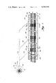
- FIG. 1 is a top plan, broken, fragmentary view of a reservoir system including a containment reservoir in combination with a railroad track section, formed in accordance with the invention, but not showing the storage reservoir of the system.
- FIG. 2 is a broken to plan view of the storage reservoir for the system of the invention.
- FIG. 3 is an enlarged vertical, transverse sectional view of the containment reservoir of FIG. 1, taken generally along the plane of line 3--3 thereof, looking in the direction of the arrows.
- FIG. 4 is an enlarged, fragmentary, transverse sectional view illustrating a portion of the side structure of a different arrangement or embodiment of the containment reservoir of FIG. 3, and more particularly a side structure formed at least in part of concrete instead of earth.
- FIG. 5 is a lengthwise sectional view taken generally along the plane of line 5--5 of FIG. 2 of the storage reservoir portion of the system (illustrted in FIGS. 1 and 2).
- FIG. 6 is an enlarged, fragmentary, detailed view of the exit or drain from the containment reservoir of the system of FIGS. 1 and 2, and illustrating the arrangement of liquid pervious fabric which encompasses the perforated drain pipe utilized in the bottom of the containment reservoir, for removing caught liquid therefrom and passing it exteriorly of the containment reservoir, to the storage reservoir.
- FIG. 6A is a reduced size, fragmentary, horizontal sectional view of the drain of FIG. 6, at one of the T-coupling connections.
- FIG. 7 is a vertical, sectional view, illustrating a sump pit means shown in the FIGS. 1 and 2 reservoir system, coacting between the containment reservoir and storage reservoir, for transferring liquid caught by the containment reservoir to the storage reservoir.
- FIGS. 8 and 9 are enlarged, fragmentary, generally diagrammatic, sectional views illustrating the preferred arrangement for forming containment reservoirs, and specifically the end sections thereof, in aligned or tandem relationship with respect to one another, and filling the containment space of such containment reservoirs with ballast material, so that such containment reservoirs can be provided in any desired length series along a railroad track section.
- FIG. 8 shows the coated fabric forming the end wall of the impervious liner for the adjacent containment reservoirs in place
- FIG. 9 illustrates the ballast having been moved into engagement with such end walls of coated fabric, to form the respective containment space for the reservoirs.
- FIG. 10 is an, enlarged, transverse, vertical sectional view of one of the track members or rails of the track section, showing the relationship between the pervious fabric layer which overlies the containment space of the containment reservoir and metal grating which is utilized intermediate the rails and adjacent to the rails, to form spaced safe walking areas over oily ballast.
- FIG. 11 is a lengthwise cross sectional view showing a storage reservoir formed generally similar to that illustrated in FIG. 5 but wherein gravity flow is utilized to transfer liquid caught in the containment reservoir to the storage reservoir rather than a pump means as is illustrted in FIG. 7.
- FIG. 12 is a top plan view of another form of storage reservoir, and one utilizing a tank structure which is surrounded by a dike formed from an earthen wall defining a containment space lined with an impervious fabric material liner.
- FIG. 13 is a sectional view taken generally along the plane of line 13--13 of FIG. 12 looking in the direction of the arrows.
- FIG. 14 is a fragmentary, sectional view taken generally along the plane of line 14--14 of FIG. 12, looking in the direction of the arrows.
- FIG. 15 is a fragmentary, generally perspective, partially broken illustration of the sectional formation of the impervious fabric liner, and the overlapping relationship of the sections thereof in the formation of the dike storage reservoir of FIG. 12.
- FIG. 16 is a sectional view taken generally along the plane of line 16--16 of FIG. 12, looking in the direction of the arrows.
- FIG. 17 is a fragmentary sectional view similar to FIG. 6, but illustrating another embodiment of drain for a containment reservoir.
- FIG. 18 is a fragmentary sectional view generally similar to FIG. 4, but embodying the drain arrangement of FIG. 17, and illustrating flashing attached to the existing side wall of the containment reservoir and coating with the side wall portion of the flexible liner, for preventing undesired leakage of liquid running into the reservoir from the top of the concrete side wall abutment.
- FIG. 19 is a view generally similar to that of FIG. 18, but illustrating another embodiment of flashing seal arrangement, and in an environment wherein the flashing seal is installed at the time of constructing the concrete side wall abutment of the reservoir.
- FIG. 21 is a vertical sectional view taken generally along the plane of line 21--21 of FIG. 20 looking in the direction of the arrows, and showing the overlying railroad track section.
- FIG. 22 is an enlarged vertical sectional view taken generally along the plane of line 22--22 of FIG. 20 looking in the direction of the arrows.
- FIG. 23 is an enlarged vertical sectional view showing an alternate seaming arrangement for formation of predetermined size of liner for a reservoir, and one which can be accomplished at the site.
- FIGS. 1 and 2 there is illustrated, a plan view of the system for catching and storing liquids in accordance with the invention, and comprising a containment reservoir 10, a storage reservoir 12 (FIG. 2) and means coating between the containment reservoir and the storage reservoir for transferring liquid caught by the containment reservoir to the storage reservoir.
- the containment reservoir is shown in combination with a railroad track section 16 (FIG. 1) which overlies the containment reservoir 10 so that any liquid dripping down on spilled from railroad vehicles passing over or parked on track section 16, will be caught in the embodiment reservoir for subsequent handling, as will be hereinafter described.
- the railroad track section 16 comprises spaced rails 18 and 20 (FIG. 1) which are supported in the conventional manner on ties 22 which in this case are shown as being wood ties. However, any suitable type of tie structure including concrete ties may be utilized.
- the containment reservoir 10 extends beneath and laterally of track section 16, and opens upwardly and encompasses the railroad track section for a predetermined portion of the length thereof. Only one containment reservoir is illustrated in FIG. 1 but it will be undersood that a plurality of the containment reservoirs could be provided in tandem relationship with respect to one another along a track section for increasing the lengthwise dimension of containment reservoir structure, and as will be hereinafter described in greater detail in connection with FIGS. 8 and 9 of the application drawings.
- the containment reservoir illustrated comprises a pit or excavation defining a containment space covered or lined with a flexible liner 24 (FIG. 3) which is impervious to passage of liquid therethrough from the containment reservoir into the surrounding ground area.
- the liner may be of the type disclosed in the aforementioned U.S. patent application Ser. No. 5,699 in the name of Robert W. Luebke, now U.S. Pat. No. 4,296,884, and reference may be had to such patent application for a detailed description of suitable construction of such liner.
- the liner prevents the escape of liquid caught in the containment reservoir from seeping or escaping into the adjacent ground area, and in the manner described, for instance, in aforementioned Ser. No. 5,699, now U.S. Pat. No. 4,296,884.
- the impervious layer 24a (FIG. 3) of the liner in this embodiment preferably faces inwardly, as shown. However, such layer 24a could face outwardly.
- the contaiment reservoir is preferably completely filled with lump-like material, such as railroad bed ballast comprising stones or the like, conventionally utilized in conjunction with railroad track installations.
- Such ballast bed has little if any fines, to aid in preventing clogging of the bed, and will readily pass therethrough liquid caught by the containment reservoir.
- the ties 22 as can be best seen in FIG. 3, are embedded in the ballast bed 26, and thus are held in predetermined position and support the track members 18 and 20 thereon with the track members being connected or coupled to the ties 22 in any suitable or conventional manner.
- the top of the containment reservoir may be covered by a layer 28 of pervious fabric material, such as the non-woven fabric identified in aforementioned U.S. patent application Ser. No. 5,699, now U.S. Pat. No. 4,296,884 with such upper layer 28 extending between the rail members 18 and 20 and laterally of the respective rail member to the exterior side boundry of the containment reservoir.
- the pervious layer 28 of material is maintained in place, and may be weighted down or held in place intermediate the rail members and on either lateral side thereof for predetermined distance outwardly therefrom, by a relatively thin layer 32 of aggregate material such as the aforementioned ballast material or some other porous material for aiding in weighing the porous fabric layer 28 down against the underlining ballast layer.
- Metal grating sections 30 may be spaced along the track as shown in FIG. 1, providing safe footing areas, and aiding in holding down the underlying pervious layer 28.
- liquid such as petroleum based fuel drips down from, say for instance diesel locomotive on the track section 16
- the grating 30 or through the particle weigh down layer 32 will pass through the grating 30 or through the particle weigh down layer 32, then through the porous underlying fabric layer 2 in the ballast filled reservoir, where the oil will drain down to drain section 36 (FIGS. 3 and 6) where it is adapted to be removed from the containment reservoir.
- Drain section 36 in the embodiment illustrated comprises lengthwise or longitudinally extending perforated pipe sections 38 which are layed in a depression or recess 40 extending in the embodiment illustrated along one side wall 41 of the containment reservoir, as best seen for instance in FIGS. 1 and 3.
- the liner 24, forming the containment reservoir bottom and side surfaces, as can be best seen in FIG. 6, extends about the lower portion of the perforated pipe 38 and then upwardly to form the adjacent side wall 41 of the containment reservoir.
- Pipe sections 38 as aforementioned are perforated along their lengthwise and circumferential extends as at 42, with liquid caught in the containment reservoir draining into the perforated pipe sections from whence it is removed from the containment reservoir via T connections 44, spaced along the perforated pipe sections 38 and coupled therewith.
- Pipe sections 38 may be formed of for instance plastic, or any suitable material, with polyvinylchloride (PVC) plastic being suitable.
- a filter layer or envelope 46 of porous fabric material generally encompassing the perforated pipe 38 and T couplings thereof, for preferably the full lengthwise extent of the pipe sections 38, and which in the embodiment illustrated is coupled by means of a fastening arrangement 48 at each T connection 44, so that liquid draining down into the perforated pipe is generally filtered, so as to prevent the accumulation of fines into the perforated pipe sections 38.
- Filter envelope 46 may be comprised of the same porous fabric material that forms the upper layer 28 covering the containment reservoir.
- Fastening arrangements 48 at the location where each of the T couplings 44 extend through the liner wall of the containment reservoir also provide a sealing arrangement, so as to prevent liquid in the reservoir from inadvertently seeping or flowing out of the containment reservoir along the exteriors of the T connections.
- Such sealing arrangement comprises a pair of spaced rings or apertured plates 52, 54 respectively disposed interiorly and exteriorly of the reservoir wall, and connected by threaded fastener means 56, with the side of the impervious fabric liner 24 being received and clamped between the rings, in tight sealing relationship.
- a rubber or neoprene flanged sleeve 58 coacting with and extending between the clamping rings 52, 54 and the exterior surface of the adjacent T coupling section 59, which extends through a complementary opening provided in the liner side wall 41.
- Sleeve 58 is clamped to the exterior of the T coupling section 59 as by means of a metal or plastic ring clamp 60, thus, insuring that liquid passing through filter layer or envelope 46 and into the perforated pipe 38 can not run along the exteriors of the T couplings 44 and escape from the containment reservoir into the adjacent ground areas. Ballast is filled into the envelope 46 about pipe 38 prior to losing or overlapping the seam thereof as at 62, after which the remainder of the containment space of the containment reservoir 10 is filled with ballast or lump material as shown in FIGS. 3 and 6.
- the T couplings 44 are coupled as by means of pipe section 64 which form passageways to a main or common pipe or passageway 66 which in turn extends into communication as at 68 (FIG. 7) with a sump well or pit 70.
- Pipe sections 64 and 66 are arranged to provide gravity flow of liquid therethrough.
- Well 70 is lined with some suitable liquid impervious material and in this instance being shown lined with precast concrete sections 70a, 70b, so that the liquid as it drains from the containment reservoir 10 by gravity, flows into the well 70, until removed as will be hereinafter described.
- the well 70 is preferably covered by means of a manhole cover 72, with a ladder 74 being provided for providing ready access into the bottom of the well.
- a submergible preferably electrical drain pump 76 is positioned in the well bottom, and is coupled by means of piping 78 to storage reservoir 12 (FIG. 2). Liquid from the well 70 is pumped by pump 76 into the storage reservoir, with actuation and deactuation of such pump preferably occurring automatically upon rising and falling of the liquid in the well to a predetermined level.
- the storage reservoir 12 in the embodiment illustrated in FIGS. 2 and 5 comprises a ground pit or excavation 80 in which a flexible liquid impervious liner 82 has been laid, with the liner preferably being formed of the material aforedescribed in conjunction with the liner of the containment reservoir 10.
- the liner 82 may be formed of a plurality of strips of the liquid impervious material overlapped, as at 82a and sealed or attached together as by means of known adhesive materials.
- the storage reservoir is comparatively readily formed, is open at its top as shown, and with the pipe 78 from the pump 76 in well 70 (FIG. 7) extending into discharge coaction with the storage reservoir, as shown in FIGS. 2 and 5, for transfer of the liquid from the containment reservoir into the storage reservoir.
- the upper ends 84 of the side wall sections of the liner 82 in the storage reservoir are preferably weighted down by the earth portions 86 as shown in FIG. 5, thus anchoring the liner in the earthen pit 80 and preventing its shifting. While the liner has been shown for illustrative purposes in spaced relation to at least a portion of the defining earthen surfaces of the pit, (i.e.
- the liner 82 is supported by such earthen surfaces and is in engagement therewith. While the rubberized layer 82b of the liner is shown as facing inwardly, the liner may be reserved so that layer 82b faces outwardly and engages the earthen surfaces of the receiving pit.
- FIG. 11 there is disclosed another embodiment of storage reservoir 12'.
- the reservoir is generally similar in construction to that in the FIGS. 2 and 5 embodiment except that the inlet pipe 78' for liquid from the containment reservoir 10 rather than being coupled to a pump disposed in a sump well, as in the first described embodiment, is gravity feed from the containment reservoir into the storage reservoir 12', so that the gravity causes the flow of liquid received in pipe system 64, 66 into the storage reservoir 12', until subsequently removed for, for instance, reclaiming purposes.
- system could include a well (similar to well 70 of FIGS. 1 and 7) where the fluid would pass into prior to flowing by gravity into the pipe 78', such a well aiding in settling out impurities in the liquid prior to the latter's movement, by gravity, via pipe 78' into the storage reservoir 12'.
- FIGS. 12-16 there is illustrated a further embodiment of storage reservoir 12" which instead of being formed by a substantial excavation or pit in the ground, is formed substantially at ground level with dike walls, such as earthen or clay walls 88 disposed in encompassing relation to a reservoir space 88a, having a flexible liquid impervious liner 82' laid therein, and with a containment tank 90 being mounted in the lined containment space.
- the liner 82' forming the bottom and side wall surfaces of the reservoir, extend along the bottom surface of the containment space and up the dike walls on the interior surfaces thereof, and then run across at least a portion of the upper section of the dike wall as at 90a.
- Weight means such as the layer of dirt or soil 92 can be utilized to anchor or hold the liner in position on the dike walls.
- Liner 82' may be the same as or generally similar to aforediscussed liner 82 of the FIGS. 5 and 11 embodiments, and likewise may be reversed so that the rubberized or impervious layer 82b' faces outwardly to engage the confronting earthen surfaces, rather than facing inwardly as illustrated.
- Tank 90 which may be formed of for instance metal, or of any other suitable material, supported on, in the embodiment illustrated, concrete piers 94 with the tank being surrounded by dike walls 88 encompassing the area which the tank 90 occupies.
- the dike and associated liner 82' is adapted to retain any liquid from the tank which overflows or spills (or in the event of bursting of the tank) to prevent such liquid from seeping into the adjacent ground areas.
- the stock material for the liner may be provided in strip sections disposed in overlapped relation, as at 82]a', generally similar to the FIGS. 5 and 11 embodiments. Where the liner sections meet the piers, the liner can be run up the sides and ends of the associated pier as illustrated at 96 in FIGS. 15 and 16.
- the liner material is able to be readily cut by sharp cutting instruments, and thus the laying of the liner of strips or rows from packages or rolls of liner stock, into the earthen reservoir dike space, is materially facilitated.
- the liner portions 96 extending upwardly about the piers 94 are preferably fastened by suitable adhesives to the piers to make a liquid tight connection with respect thereto, such adhesive being resistant or uneffected by the petroleum based liquids beings stored.
- the tank 90 may have vent pipes 98 thereon for overflow of liquid in the event that too much liquid is attempted to be inserted into the tank via its entry pipe 78, as well as means providing for venting of vapor, as for instance by vapor pipes 100.
- An outlet flow valve 102 may also be provided on the tank.
- FIGS. 8 and 9 illustrate a method of forming the end wall portions of adjacent containment reservoir formed in aligned or tandem relation with respect to one another along a railroad track section, thus providing for any desired length of containment reservoir system irrespective of the stock material for forming the flexible reservoir liners, coming in predetermined standard lengths.
- the end wall sections 104 and 104a of the liner 24 of the adjacent containment reservoirs may be looped, as at 106, about a transverse beam 108 extending across the excavation for the reservoir, with a top member 110 laid on beam 108 to maintain the vertical orientation of the flexible end walls, and then the ballast 26 is filled or pushed into the space 112, and against the walls, to maintain the latter's vertical condition.
- Beam 108 and holder member 110 can then be removed, and the distal end of the liner end walls tucked downwardly as illustrated in FIG. 9.
- the top porous layer 28 of fabric may then be applied to the respective reservoir ballast bed as illustrated, and maintained in position by, for instance, ballast layer 32.
- the upper ends of the side wall sections 114 of the liner 24 may be retained in position by the overlying earthen layer 116, similar to the first described containment and storage reservoirs.
- drain section 36' which is somewhat similar to that (e.g. 36) of the FIG. 6 embodiment previously discussed in conjunction with FIGS. 3 through 6A.
- the pipe sections 38' which may be of plastic pipe as in the first described embodiment, are perforated only adjacent the lower portions thereof, as at 42' along the lengthwise extent of pipe sections 38', so that liquid caught in the containment reservoir drains into the perforated pipe sections 38' only at the lower portions thereof, and from whence it is removed from the containment reservoir via the T connections 44 spaced along the perforated pipe sections 38' and coupled therewith in a similar manner as disclosed in the first described embodiment of drain.
- the envelope 46' of pervious fabric material encompasses primarily the perforated pipe 38' in generally direct engagement therewith, and is not coupled to the fastening arrangement 48 at each T connection 44 as in the first described embodiment. Moreover, the envelope 46' is not filled with ballast as in the first described embodiment, but more or less directly engages the pipe 38' and associated section of the T coupling.
- FIG. 17 drain arrangement is generally simpler to install and yet effectively provides for removal of liquid from the containment reservoir.
- FIG. 18 there is disclosed a containment reservoir 10 which embodies flashing 118 running along the interior sides of the reservoir.
- flashing 118 is secured as by means of fasteners 120 to an existing concrete abutment 121 partially defining the containment reservoir. This could occur for instance at a fueling station disposed along a railroad track section in which the top surface 121a of the concrete abutment 121 slopes toward the reservoir proper.
- Flashing 118 secured to the side of an existing concrete abutment would preferably have some sealing compound inserted, as at 122, between the flashing and the confronting abutment side surface, and the upper end 124 of the side wall section 41 of the flexible liner 14, is inserted between the flashing and the concrete abutment.
- FIG. 19 there is shown a similar arrangement of flashing member 118' but in this arrangement, the flashing member has an offset section 126 which is embedded or installed in the concrete abutment 121'0 when it is initially formed, so that the flashing is integrally joined with the fueling station apron, and therefore it is not necessary to attach the same utilizing fasteners.
- the side wall section 41 of the flexible liner is wedged or inserted between the flashing 118' and the confronting surface of the concrete abutment 121' in the same manner as aforedescribed in connection with the FIG. 18 embodiment.
- drain 36" for a containment reservoir of the general type illustrated in FIGS. 1 and 3.
- the drain is formed of concrete chamber members 38", defining a space 130, which is adapted to receive therein the liquid from the liner formed reservoir 10".
- Drain members 38" are preferably preformed, and may be formed of concrete as shown.
- Members 38" are open at the top thereof, with such open top being covered over by a grating 132 formed of any suitable material, such as for instance metal or plastic.
- the grating member 132 rests on shoulders 134 provided in drain member 38", so that the grating in effect forms a general continuation of the bottom surface of the containment reservoir as defined by the flexible liner 24'.
- the bottom defining wall of the liner 24' is tucked as at 135 into the space between the grating 132 and the confronting surface of the drain member 38" and thus is securely held therein in anti-leak relation.
- an envelope or enclosure 136 formed of liquid porous material, which may be of the same general type and composition as that of the top layer 28 covering the top of the containment reservoir, with the envelope defining an enclosure in which is received ballast material 26.
- the ballast filled envelope 136 covers the grating surface in overlapping relation (FIG. 22) and aids in preventing fines from clogging the openings in the grating 132.
- a pipe 64' is coupled to each of the drain members 38", as can be best seen from FIGS. 20 and 22, and communicates with pipe passage 66 in a similar manner as in the first described FIG.
- FIGS. 1 through 3 The structural arrangement of the remainder of the containment reservoir may be generally similar to that of the first described embodiment illustrated in FIGS. 1 through 3. It will be seen that liquid flowing down an inadvertent spill from vehicles positioned on the track section 16 disposed above the containment reservoir, will filter down through the containment reservoir top pervious layer 28 into the reservoir chamber and then into and through the envleope 136 and associated ballast, and then through the grating 132 into the drain member 38" from whence it will flow by gravity out through pipe 64'.
- FIG. 23 there is illustrated a liner of the multi-layer type aforediscussed in connection with the other embodiments, and wherein the strips of the liner material can be adhered to one another by a resilient joint 140 which can be secured by suitable known adhesives as at 142, and, such as rubber bonding adhesives, to the junction between adjacent strips of the liner material, to provide a continuous selected width of liner.
- suitable known adhesives as at 142, and, such as rubber bonding adhesives
- the invention provides a novel arrangement or system for catching and storing liquids along railroad track section, and a system formed of a flexible liner containment reservoir, a flexible liner storage reservoir, and means coacting between the containment and storage reservoirs for transferring liquid caught in the containment reservoir to a storage reservoir.
- the invention also provides a system of the above type which includes drain structure including a filtering means coacting in certain embodiments with perforated drain pipe for removing liquid from the containment reservoir, and coacting in another embodiment with a formed drain chamber including perforated means for supporting filtering means thereon, with the filtering means resisting the transmittal of contaminants to the drain pipe or to the drain chamber.
- the invention also provides a novel method of collecting and storing liquids such as petroleum based oils, along a railroad track section environment or the like.
Landscapes
- Engineering & Computer Science (AREA)
- Architecture (AREA)
- Civil Engineering (AREA)
- Structural Engineering (AREA)
- Mechanical Engineering (AREA)
- Sewage (AREA)
Abstract
Description
Claims (9)
Priority Applications (1)
| Application Number | Priority Date | Filing Date | Title |
|---|---|---|---|
| US06/290,481 US4366846A (en) | 1979-06-29 | 1981-08-06 | Method for collecting and storing liquid from along a railroad track section |
Applications Claiming Priority (2)
| Application Number | Priority Date | Filing Date | Title |
|---|---|---|---|
| US06/053,705 US4299697A (en) | 1979-06-29 | 1979-06-29 | Liquid containment and storage system for railroad track |
| US06/290,481 US4366846A (en) | 1979-06-29 | 1981-08-06 | Method for collecting and storing liquid from along a railroad track section |
Related Parent Applications (1)
| Application Number | Title | Priority Date | Filing Date |
|---|---|---|---|
| US06/053,705 Division US4299697A (en) | 1979-06-29 | 1979-06-29 | Liquid containment and storage system for railroad track |
Publications (1)
| Publication Number | Publication Date |
|---|---|
| US4366846A true US4366846A (en) | 1983-01-04 |
Family
ID=26732154
Family Applications (1)
| Application Number | Title | Priority Date | Filing Date |
|---|---|---|---|
| US06/290,481 Expired - Fee Related US4366846A (en) | 1979-06-29 | 1981-08-06 | Method for collecting and storing liquid from along a railroad track section |
Country Status (1)
| Country | Link |
|---|---|
| US (1) | US4366846A (en) |
Cited By (46)
| Publication number | Priority date | Publication date | Assignee | Title |
|---|---|---|---|---|
| US4592846A (en) * | 1985-09-03 | 1986-06-03 | Ppg Industries, Inc. | Method and reservoir for in-ground containment of liquid waste |
| US4593760A (en) * | 1984-01-04 | 1986-06-10 | The Upjohn Company | Removal of volatile contaminants from the vadose zone of contaminated ground |
| US4622790A (en) * | 1984-04-02 | 1986-11-18 | Johansson Jan E | Device for relieving floors on ground in buildings |
| US4660639A (en) * | 1984-01-04 | 1987-04-28 | The Upjohn Company | Removal of volatile contaminants from the vadose zone of contaminated ground |
| US4679963A (en) * | 1986-05-27 | 1987-07-14 | Heath Robert G | Playground construction |
| US4682911A (en) * | 1984-03-06 | 1987-07-28 | Mpc Containment Systems, Ltd. | Secondary containment systems especially well suited for hydrocarbon storage and delivery systems |
| US4741644A (en) * | 1985-04-11 | 1988-05-03 | Finic, B.V. | Environmental cut-off and drain |
| US4778310A (en) * | 1986-11-14 | 1988-10-18 | Mpc Containment Systems, Ltd. | Means for installing membranes in containment pits for tanks storing liquids |
| US4808024A (en) * | 1987-03-30 | 1989-02-28 | Haas Jon A | Method for installing a pavement underdrain |
| US4818151A (en) * | 1985-03-08 | 1989-04-04 | Mpc Containment Systems | Secondary containment systems especially well suited for hydrocarbon storage and delivery systems |
| US4863312A (en) * | 1983-07-26 | 1989-09-05 | Finic, B. V. | Underground leachate and pollutant drainage barrier system |
| USRE33102E (en) * | 1984-01-04 | 1989-10-31 | The Upjohn Company | Removal of volatile contaminants from the vadose zone of contaminated ground |
| US4923330A (en) * | 1987-12-31 | 1990-05-08 | Detommaso Stephen C | Storm water injection well |
| US4923333A (en) * | 1988-05-12 | 1990-05-08 | Timmons Robert D | Lysimeter for leak detection and method of assembly thereof |
| US4960345A (en) * | 1989-01-27 | 1990-10-02 | Turf Drain Company Of America, Inc. | System for construction of golf course sand bunkers |
| US4978249A (en) * | 1989-03-14 | 1990-12-18 | Killman Troy H | Safe, fluid-storage system |
| US5026207A (en) * | 1989-09-06 | 1991-06-25 | Heath Robert G | Recreational area construction |
| US5067850A (en) * | 1990-08-31 | 1991-11-26 | Gray Engineering, Inc. | Apparatus for detection and containment of pollutants in a drainage system |
| US5118230A (en) * | 1990-12-27 | 1992-06-02 | Justice Donald R | Method and apparatus for installation of leachate containment system |
| US5360067A (en) * | 1993-05-17 | 1994-11-01 | Meo Iii Dominic | Vapor-extraction system for removing hydrocarbons from soil |
| US5554290A (en) * | 1995-04-11 | 1996-09-10 | Geraghty & Miller, Inc. | Insitu anaerobic reactive zone for insitu metals precipitation and to achieve microbial de-nitrification |
| US5575589A (en) * | 1995-04-11 | 1996-11-19 | Geraghty & Miller, Inc. | Apparatus and method for removing volatile contaminants from phreatic water |
| US5588490A (en) * | 1995-05-31 | 1996-12-31 | Geraghty & Miller, Inc. | Method and system to achieve two dimensional air sparging |
| US5664911A (en) * | 1991-05-03 | 1997-09-09 | Iit Research Institute | Method and apparatus for in situ decontamination of a site contaminated with a volatile material |
| US5685668A (en) * | 1994-09-07 | 1997-11-11 | Justice; Donald R. | Barrier wall installation system |
| US6007274A (en) * | 1997-05-19 | 1999-12-28 | Arcadis Geraghty & Miller | In-well air stripping, oxidation, and adsorption |
| US6116816A (en) * | 1998-08-26 | 2000-09-12 | Arcadis Geraghty & Miller, Inc. | In situ reactive gate for groundwater remediation |
| US6143177A (en) * | 1995-04-11 | 2000-11-07 | Arcadis Geraghty & Miller, Inc. | Engineered in situ anaerobic reactive zones |
| US6290143B1 (en) | 1996-05-02 | 2001-09-18 | Century Group, L.L.C. | Apparatus and method for collecting liquid spillage at rail facilities |
| US20030047523A1 (en) * | 2000-02-11 | 2003-03-13 | Solidification Products International, Inc. | Filtration of hydrocarbon containing liquid |
| US20030108387A1 (en) * | 2001-10-27 | 2003-06-12 | Airikkala Pentti Juhani | Vehicle arrest apparatus |
| US20030215290A1 (en) * | 2002-03-18 | 2003-11-20 | Cash Alan Brian | Systems and methods for the on-site treatment and disposal of contaminated soils and sediments |
| US20070025817A1 (en) * | 2005-07-27 | 2007-02-01 | Sheridan Terence G | Water retention system |
| US20080086024A1 (en) * | 2006-09-27 | 2008-04-10 | Hazlebeck David A | Hydrolysis system and process for devices containing energetic material |
| US20090148235A1 (en) * | 2007-12-11 | 2009-06-11 | Astral Property Pty Limited | Transport Corridor infiltration system |
| US20100294705A1 (en) * | 2009-05-22 | 2010-11-25 | Henry Eric M | Water drainage and harvesting system for an artificial turf environment |
| US20110278302A1 (en) * | 2010-05-08 | 2011-11-17 | Van Fossen Peter A | Method for manufacturing a secondary containment liner system |
| US20120247572A1 (en) * | 2009-12-15 | 2012-10-04 | Guardian Venture Oil & Gas Sdn. Bhd. | Conductive tank sump and dispenser sump, and method of earthing process of the same, and electrically-conductive composition for fabrication of tank sump |
| ITFI20130047A1 (en) * | 2013-03-06 | 2014-09-07 | Elettricita Renai S R L | SUCTION SYSTEM FOR FLAMMABLE LIQUIDS OR POLLUTANTS SPILLED INSIDE AN ENVIRONMENT AS A ROAD OR RAILWAY GALLERY |
| FR3007725A1 (en) * | 2013-06-28 | 2015-01-02 | Bouygues En & Services | SYSTEM FOR RECOVERING USED FLUIDS FROM A TRAIN |
| WO2015114537A1 (en) | 2014-01-28 | 2015-08-06 | Rangoni Cristiano | Method for waterproofing railway bridges and waterproofing material for carrying out said method |
| US20170191230A1 (en) * | 2016-01-06 | 2017-07-06 | BunkersPlus LLC | Golf bunker liner |
| US20180021654A1 (en) * | 2016-01-06 | 2018-01-25 | BunkersPlus LLC | Golf course sand bunker with liner and method of making the same |
| US20220196012A1 (en) * | 2020-09-30 | 2022-06-23 | Solidification Products International, Inc. | Sump pump system and methods for removing synthetic ester-based fluids from an emulsion |
| US20230030765A1 (en) * | 2019-12-23 | 2023-02-02 | Rockwool A/S | A storm water management system |
| RU223795U1 (en) * | 2024-01-09 | 2024-03-04 | Акционерное общество "Рузаевский завод химического машиностроения" (АО "Рузхиммаш") | ISOTHERMAL CAR |
Citations (18)
| Publication number | Priority date | Publication date | Assignee | Title |
|---|---|---|---|---|
| US679536A (en) * | 1901-03-20 | 1901-07-30 | Thomas E Mccann | Filter. |
| US1081515A (en) * | 1912-05-10 | 1913-12-16 | David C Reinohl | Combined settling-tank and filter. |
| US1397452A (en) * | 1921-06-28 | 1921-11-15 | Andrew J Reed | Apparatus for purifying water |
| US2492177A (en) * | 1945-01-31 | 1949-12-27 | Olsen Oliver Ingvard | Combination railroad tie and drainage system |
| US3474625A (en) * | 1967-05-29 | 1969-10-28 | Phillips Petroleum Co | Laminates of a polyolefin fabric and/or film and asphaltic material |
| US3505820A (en) * | 1967-12-28 | 1970-04-14 | Phillips Petroleum Co | Leak detection for lined reservoirs |
| US3587964A (en) * | 1969-04-18 | 1971-06-28 | Meadows W R Inc | Protective course for bridge deck |
| US3705851A (en) * | 1971-11-15 | 1972-12-12 | Robert C Brauer | Waste disposal system |
| US3754362A (en) * | 1970-10-29 | 1973-08-28 | Akzona Inc | Vertical drainage system |
| US3773255A (en) * | 1972-01-13 | 1973-11-20 | Armco Steel Corp | Fluid collection assembly for railroad roadbed |
| US3795180A (en) * | 1969-02-26 | 1974-03-05 | Conwed Corp | Plastic net deck surface and drainage unit |
| US3854291A (en) * | 1972-12-26 | 1974-12-17 | E Perkins | Self-cleaning filter for hydrological regeneration |
| US3872007A (en) * | 1972-11-29 | 1975-03-18 | Phillips Petroleum Co | Container for plurality of immiscible liquids |
| US3936380A (en) * | 1972-08-02 | 1976-02-03 | Johann Boske | Means to counteract a clogging of drain pipes |
| US4010896A (en) * | 1976-03-25 | 1977-03-08 | Stockton William N | Modular liquid collection system for railroad roadbeds |
| US4039451A (en) * | 1975-08-18 | 1977-08-02 | Alvin Jack Smith | Evaporation of treated waste water |
| US4045964A (en) * | 1975-12-15 | 1977-09-06 | Barclay James A | Subterranean panel drain |
| US4193873A (en) * | 1978-05-30 | 1980-03-18 | Thrasher Donald D | Manure collection and storage system |
-
1981
- 1981-08-06 US US06/290,481 patent/US4366846A/en not_active Expired - Fee Related
Patent Citations (18)
| Publication number | Priority date | Publication date | Assignee | Title |
|---|---|---|---|---|
| US679536A (en) * | 1901-03-20 | 1901-07-30 | Thomas E Mccann | Filter. |
| US1081515A (en) * | 1912-05-10 | 1913-12-16 | David C Reinohl | Combined settling-tank and filter. |
| US1397452A (en) * | 1921-06-28 | 1921-11-15 | Andrew J Reed | Apparatus for purifying water |
| US2492177A (en) * | 1945-01-31 | 1949-12-27 | Olsen Oliver Ingvard | Combination railroad tie and drainage system |
| US3474625A (en) * | 1967-05-29 | 1969-10-28 | Phillips Petroleum Co | Laminates of a polyolefin fabric and/or film and asphaltic material |
| US3505820A (en) * | 1967-12-28 | 1970-04-14 | Phillips Petroleum Co | Leak detection for lined reservoirs |
| US3795180A (en) * | 1969-02-26 | 1974-03-05 | Conwed Corp | Plastic net deck surface and drainage unit |
| US3587964A (en) * | 1969-04-18 | 1971-06-28 | Meadows W R Inc | Protective course for bridge deck |
| US3754362A (en) * | 1970-10-29 | 1973-08-28 | Akzona Inc | Vertical drainage system |
| US3705851A (en) * | 1971-11-15 | 1972-12-12 | Robert C Brauer | Waste disposal system |
| US3773255A (en) * | 1972-01-13 | 1973-11-20 | Armco Steel Corp | Fluid collection assembly for railroad roadbed |
| US3936380A (en) * | 1972-08-02 | 1976-02-03 | Johann Boske | Means to counteract a clogging of drain pipes |
| US3872007A (en) * | 1972-11-29 | 1975-03-18 | Phillips Petroleum Co | Container for plurality of immiscible liquids |
| US3854291A (en) * | 1972-12-26 | 1974-12-17 | E Perkins | Self-cleaning filter for hydrological regeneration |
| US4039451A (en) * | 1975-08-18 | 1977-08-02 | Alvin Jack Smith | Evaporation of treated waste water |
| US4045964A (en) * | 1975-12-15 | 1977-09-06 | Barclay James A | Subterranean panel drain |
| US4010896A (en) * | 1976-03-25 | 1977-03-08 | Stockton William N | Modular liquid collection system for railroad roadbeds |
| US4193873A (en) * | 1978-05-30 | 1980-03-18 | Thrasher Donald D | Manure collection and storage system |
Cited By (69)
| Publication number | Priority date | Publication date | Assignee | Title |
|---|---|---|---|---|
| US4863312A (en) * | 1983-07-26 | 1989-09-05 | Finic, B. V. | Underground leachate and pollutant drainage barrier system |
| US4593760A (en) * | 1984-01-04 | 1986-06-10 | The Upjohn Company | Removal of volatile contaminants from the vadose zone of contaminated ground |
| US4660639A (en) * | 1984-01-04 | 1987-04-28 | The Upjohn Company | Removal of volatile contaminants from the vadose zone of contaminated ground |
| USRE33102E (en) * | 1984-01-04 | 1989-10-31 | The Upjohn Company | Removal of volatile contaminants from the vadose zone of contaminated ground |
| US4682911A (en) * | 1984-03-06 | 1987-07-28 | Mpc Containment Systems, Ltd. | Secondary containment systems especially well suited for hydrocarbon storage and delivery systems |
| US4622790A (en) * | 1984-04-02 | 1986-11-18 | Johansson Jan E | Device for relieving floors on ground in buildings |
| US4818151A (en) * | 1985-03-08 | 1989-04-04 | Mpc Containment Systems | Secondary containment systems especially well suited for hydrocarbon storage and delivery systems |
| US4741644A (en) * | 1985-04-11 | 1988-05-03 | Finic, B.V. | Environmental cut-off and drain |
| US4592846A (en) * | 1985-09-03 | 1986-06-03 | Ppg Industries, Inc. | Method and reservoir for in-ground containment of liquid waste |
| US4679963A (en) * | 1986-05-27 | 1987-07-14 | Heath Robert G | Playground construction |
| US4778310A (en) * | 1986-11-14 | 1988-10-18 | Mpc Containment Systems, Ltd. | Means for installing membranes in containment pits for tanks storing liquids |
| US4808024A (en) * | 1987-03-30 | 1989-02-28 | Haas Jon A | Method for installing a pavement underdrain |
| US4923330A (en) * | 1987-12-31 | 1990-05-08 | Detommaso Stephen C | Storm water injection well |
| US4923333A (en) * | 1988-05-12 | 1990-05-08 | Timmons Robert D | Lysimeter for leak detection and method of assembly thereof |
| US4960345A (en) * | 1989-01-27 | 1990-10-02 | Turf Drain Company Of America, Inc. | System for construction of golf course sand bunkers |
| US4978249A (en) * | 1989-03-14 | 1990-12-18 | Killman Troy H | Safe, fluid-storage system |
| US5026207A (en) * | 1989-09-06 | 1991-06-25 | Heath Robert G | Recreational area construction |
| US5067850A (en) * | 1990-08-31 | 1991-11-26 | Gray Engineering, Inc. | Apparatus for detection and containment of pollutants in a drainage system |
| US5118230A (en) * | 1990-12-27 | 1992-06-02 | Justice Donald R | Method and apparatus for installation of leachate containment system |
| US5664911A (en) * | 1991-05-03 | 1997-09-09 | Iit Research Institute | Method and apparatus for in situ decontamination of a site contaminated with a volatile material |
| US5360067A (en) * | 1993-05-17 | 1994-11-01 | Meo Iii Dominic | Vapor-extraction system for removing hydrocarbons from soil |
| US5685668A (en) * | 1994-09-07 | 1997-11-11 | Justice; Donald R. | Barrier wall installation system |
| US5575589A (en) * | 1995-04-11 | 1996-11-19 | Geraghty & Miller, Inc. | Apparatus and method for removing volatile contaminants from phreatic water |
| US5554290A (en) * | 1995-04-11 | 1996-09-10 | Geraghty & Miller, Inc. | Insitu anaerobic reactive zone for insitu metals precipitation and to achieve microbial de-nitrification |
| US6632364B1 (en) | 1995-04-11 | 2003-10-14 | Arcadis G & M | Engineered in situ anaerobic reactive zones |
| US6143177A (en) * | 1995-04-11 | 2000-11-07 | Arcadis Geraghty & Miller, Inc. | Engineered in situ anaerobic reactive zones |
| US6322700B1 (en) | 1995-04-11 | 2001-11-27 | Arcadis Geraghty & Miller | Engineered in situ anaerobic reactive zones |
| US5588490A (en) * | 1995-05-31 | 1996-12-31 | Geraghty & Miller, Inc. | Method and system to achieve two dimensional air sparging |
| US6415987B2 (en) | 1996-05-02 | 2002-07-09 | Century Group L.L.C. | Method for collecting liquid spillage at rail facilities |
| US6290143B1 (en) | 1996-05-02 | 2001-09-18 | Century Group, L.L.C. | Apparatus and method for collecting liquid spillage at rail facilities |
| US6102623A (en) * | 1997-05-19 | 2000-08-15 | Arcadis Geraghty & Miller, Inc. | In-well air stripping, oxidation, and adsorption |
| US6007274A (en) * | 1997-05-19 | 1999-12-28 | Arcadis Geraghty & Miller | In-well air stripping, oxidation, and adsorption |
| US6283674B1 (en) * | 1997-05-19 | 2001-09-04 | Arcadis Geraghty & Miller | In-well air stripping, oxidation, and adsorption |
| US6254310B1 (en) | 1997-05-19 | 2001-07-03 | Arcadis Geraghty & Miller, Inc. | In-well air stripping and adsorption |
| US6116816A (en) * | 1998-08-26 | 2000-09-12 | Arcadis Geraghty & Miller, Inc. | In situ reactive gate for groundwater remediation |
| US6280118B1 (en) | 1998-08-26 | 2001-08-28 | Arcadis Geraghty & Miller, Inc. | In situ reactive gate |
| US20030047523A1 (en) * | 2000-02-11 | 2003-03-13 | Solidification Products International, Inc. | Filtration of hydrocarbon containing liquid |
| US8137564B2 (en) * | 2000-02-11 | 2012-03-20 | Spi Filtration Llc | Filtration of hydrocarbon containing liquid |
| US20030108387A1 (en) * | 2001-10-27 | 2003-06-12 | Airikkala Pentti Juhani | Vehicle arrest apparatus |
| US20050169705A1 (en) * | 2001-10-27 | 2005-08-04 | Airikkala Pentti J. | Vehicle arrest apparatus |
| US7018128B2 (en) * | 2001-10-27 | 2006-03-28 | Pentti Juhani Airikkala | Vehicle arrest apparatus |
| US7021859B2 (en) | 2001-10-27 | 2006-04-04 | Pentti Juhani Airikkala | Method for slowing the progress of a vehicle |
| US20030215290A1 (en) * | 2002-03-18 | 2003-11-20 | Cash Alan Brian | Systems and methods for the on-site treatment and disposal of contaminated soils and sediments |
| US6881010B2 (en) * | 2002-03-18 | 2005-04-19 | Alan Brian Cash | Systems for on site treatment and disposal of contaminated soils and sediments |
| US20070025817A1 (en) * | 2005-07-27 | 2007-02-01 | Sheridan Terence G | Water retention system |
| US7473055B2 (en) | 2005-07-27 | 2009-01-06 | Geostorage Corporation | Water retention system |
| US7883676B2 (en) | 2006-09-27 | 2011-02-08 | General Atomics | Hydrolysis system and process for devices containing energetic material |
| US20080086024A1 (en) * | 2006-09-27 | 2008-04-10 | Hazlebeck David A | Hydrolysis system and process for devices containing energetic material |
| US7686540B2 (en) * | 2007-12-11 | 2010-03-30 | Astral Property Pty Ltd | Transport corridor infiltration system |
| US20090148235A1 (en) * | 2007-12-11 | 2009-06-11 | Astral Property Pty Limited | Transport Corridor infiltration system |
| AU2008207603B2 (en) * | 2007-12-11 | 2011-02-10 | Astral Property Pty Limited | Transport Corridor Infiltration System |
| US20100294705A1 (en) * | 2009-05-22 | 2010-11-25 | Henry Eric M | Water drainage and harvesting system for an artificial turf environment |
| US8221029B2 (en) | 2009-05-22 | 2012-07-17 | Tanya R. Sanchez | Water drainage and harvesting system for an artificial turf environment |
| US20120247572A1 (en) * | 2009-12-15 | 2012-10-04 | Guardian Venture Oil & Gas Sdn. Bhd. | Conductive tank sump and dispenser sump, and method of earthing process of the same, and electrically-conductive composition for fabrication of tank sump |
| US20120255958A1 (en) * | 2009-12-15 | 2012-10-11 | Guardian Venture Oil & Gas Sdn Bhd | Conductive tank sump and dispenser sump, and method of earthing process of the same |
| US20110278302A1 (en) * | 2010-05-08 | 2011-11-17 | Van Fossen Peter A | Method for manufacturing a secondary containment liner system |
| US8361261B2 (en) * | 2010-05-08 | 2013-01-29 | Van Fossen Peter A | Method for manufacturing a secondary containment liner system |
| ITFI20130047A1 (en) * | 2013-03-06 | 2014-09-07 | Elettricita Renai S R L | SUCTION SYSTEM FOR FLAMMABLE LIQUIDS OR POLLUTANTS SPILLED INSIDE AN ENVIRONMENT AS A ROAD OR RAILWAY GALLERY |
| WO2014136132A1 (en) * | 2013-03-06 | 2014-09-12 | Autostrade Per L'italia S.P.A. | Suction system for flammable or polluting liquids |
| FR3007725A1 (en) * | 2013-06-28 | 2015-01-02 | Bouygues En & Services | SYSTEM FOR RECOVERING USED FLUIDS FROM A TRAIN |
| WO2015114537A1 (en) | 2014-01-28 | 2015-08-06 | Rangoni Cristiano | Method for waterproofing railway bridges and waterproofing material for carrying out said method |
| US10174462B2 (en) * | 2014-01-28 | 2019-01-08 | Christiano Rangoni | Method for waterproofing railway bridges and waterproofing material for carrying out said method |
| US20170191230A1 (en) * | 2016-01-06 | 2017-07-06 | BunkersPlus LLC | Golf bunker liner |
| US20180021654A1 (en) * | 2016-01-06 | 2018-01-25 | BunkersPlus LLC | Golf course sand bunker with liner and method of making the same |
| US10220287B2 (en) * | 2016-01-06 | 2019-03-05 | BunkersPlus LLC | Golf course sand bunker with liner and method of making the same |
| US20230030765A1 (en) * | 2019-12-23 | 2023-02-02 | Rockwool A/S | A storm water management system |
| US20220196012A1 (en) * | 2020-09-30 | 2022-06-23 | Solidification Products International, Inc. | Sump pump system and methods for removing synthetic ester-based fluids from an emulsion |
| US12140139B2 (en) * | 2020-09-30 | 2024-11-12 | Solidification Products International, Inc. | Gravity flow filtration of hydrocarbons from an oil-in-water emulsion |
| RU223795U1 (en) * | 2024-01-09 | 2024-03-04 | Акционерное общество "Рузаевский завод химического машиностроения" (АО "Рузхиммаш") | ISOTHERMAL CAR |
Similar Documents
| Publication | Publication Date | Title |
|---|---|---|
| US4366846A (en) | Method for collecting and storing liquid from along a railroad track section | |
| US4352601A (en) | Permanent bin for temporary storage of hazardous materials | |
| US4296884A (en) | Containment reservoir and method | |
| US4592846A (en) | Method and reservoir for in-ground containment of liquid waste | |
| US4896705A (en) | Containment manhole | |
| US4763806A (en) | Containment manhole | |
| US4278115A (en) | Device for capturing and retaining spilt fluids | |
| US1734777A (en) | System of draining | |
| US4406403A (en) | Method of providing a containment reservoir | |
| RU2583031C2 (en) | System for localization and control of liquids | |
| US5836115A (en) | Foundation waterproofing and drainage system | |
| US4136500A (en) | Basement waterproofing system | |
| US4388357A (en) | Sheet useful as a reservoir liner | |
| US5480260A (en) | Ground water collection method and apparatus | |
| US4299697A (en) | Liquid containment and storage system for railroad track | |
| US4818151A (en) | Secondary containment systems especially well suited for hydrocarbon storage and delivery systems | |
| KR20000016216A (en) | System and method for blocking leachate by using diving back flow tank | |
| US4934866A (en) | Secondary fluid containment method and apparatus | |
| US5092709A (en) | Landfill site with leachate collection | |
| US4877350A (en) | Foundation waterproofing method | |
| US7128831B2 (en) | Pollutant containment system | |
| CA3072511A1 (en) | Surface containment system | |
| US4778310A (en) | Means for installing membranes in containment pits for tanks storing liquids | |
| US8156969B2 (en) | Underground storage tank with sediment trap | |
| US5160064A (en) | Fuel containment cover assembly |
Legal Events
| Date | Code | Title | Description |
|---|---|---|---|
| AS | Assignment |
Owner name: TRUE TEMPER RAILWAY APPLIANCES, INC., 111 EAST WAC Free format text: ASSIGNMENT OF ASSIGNORS INTEREST.;ASSIGNOR:TRUE TEMPER CORPORATION;REEL/FRAME:003988/0438 Effective date: 19820504 |
|
| AS | Assignment |
Owner name: QULINE CORPORATION, 3206 SPRING FOREST ROAD, RALEI Free format text: ASSIGNMENT OF ASSIGNORS INTEREST.;ASSIGNOR:TRUE TEMPER RAILWAY APPLIANCES, INC.;REEL/FRAME:004545/0743 Effective date: 19860316 Owner name: QULINE CORPORATION, A CORP OF N.C., NORTH CAROLINA Free format text: ASSIGNMENT OF ASSIGNORS INTEREST;ASSIGNOR:TRUE TEMPER RAILWAY APPLIANCES, INC.;REEL/FRAME:004545/0743 Effective date: 19860316 |
|
| FEPP | Fee payment procedure |
Free format text: MAINTENANCE FEE REMINDER MAILED (ORIGINAL EVENT CODE: REM.); ENTITY STATUS OF PATENT OWNER: LARGE ENTITY |
|
| AS | Assignment |
Owner name: WELLMAN QULINE, INC., A CORP. OF DE. Free format text: ASSIGNMENT OF ASSIGNORS INTEREST.;ASSIGNOR:QULINE CORPORATION, A CORP. OF N.C.;REEL/FRAME:004586/0970 Effective date: 19860530 |
|
| LAPS | Lapse for failure to pay maintenance fees | ||
| STCH | Information on status: patent discontinuation |
Free format text: PATENT EXPIRED DUE TO NONPAYMENT OF MAINTENANCE FEES UNDER 37 CFR 1.362 |
|
| FP | Lapsed due to failure to pay maintenance fee |
Effective date: 19870104 |