US4363557A - Marking device for shorthand machine - Google Patents
Marking device for shorthand machine Download PDFInfo
- Publication number
- US4363557A US4363557A US06/257,777 US25777781A US4363557A US 4363557 A US4363557 A US 4363557A US 25777781 A US25777781 A US 25777781A US 4363557 A US4363557 A US 4363557A
- Authority
- US
- United States
- Prior art keywords
- key
- marking
- housing
- base plate
- machine
- Prior art date
- Legal status (The legal status is an assumption and is not a legal conclusion. Google has not performed a legal analysis and makes no representation as to the accuracy of the status listed.)
- Expired - Lifetime
Links
Images

Classifications
-
- B—PERFORMING OPERATIONS; TRANSPORTING
- B41—PRINTING; LINING MACHINES; TYPEWRITERS; STAMPS
- B41J—TYPEWRITERS; SELECTIVE PRINTING MECHANISMS, i.e. MECHANISMS PRINTING OTHERWISE THAN FROM A FORME; CORRECTION OF TYPOGRAPHICAL ERRORS
- B41J3/00—Typewriters or selective printing or marking mechanisms characterised by the purpose for which they are constructed
- B41J3/26—Typewriters or selective printing or marking mechanisms characterised by the purpose for which they are constructed for stenographic writing
Definitions
- the invention is related to accessories for shorthand machines and is particularly directed to means for marking the margin of the shorthand paper tape of a shorthand machine for denoting portions of the notes for ready reference and recall.
- Machine shorthand operators frequently desire to mark the paper tape output produced by the shorthand machine to denote a portion or portions of the notes recorded thereon for ready reference and quick retrieval of the information there encoded. In the past, this has been accomplished by merely marking the tape with a pen or pencil or slightly tearing the tape at its margin to indicate specific portions of the notes.
- a marking device having a hinged body, the lower half of which is adhesively mounted on the cover of the machine.
- a spring-wire member is mounted in the upper half of the body and defines two legs which project outwardly therefrom to a position above and in vertical alignment with the platen.
- a foam rubber pad is disposed between the hinged halves of the body for urging the upper half of the body and the wire member into a retracted position above the platen.
- the ends of the legs of the wire member hold a pair of inking pads mounted in plastic carriers which, when engaged and depressed, strike the paper tape on the platen of the machine.
- Devices of this type interfere with the access of the platen, encumber the smooth surface of the machine cover with attachments, and as with a pen or pencil, require complete removal of the operator's hand from the machine keyboard in order to mark the paper tape.
- these devices require modification of the machine and/or removal of the cover in order to facilitate storage when not in use. Further, they require periodic re-inking.
- the present invention is directed to a marking device for use in a shorthand machine wherein the device is located intermediate of the platen and keyboard of the machine in such a manner that it does not encumber the cover and does not interfere with access to the platen or the keyboard.
- the activating keys of the marking device extend longitudinally from a keyboard-adjacent end having a finger pad to a platen-adjacent end containing a marking instrument.
- the keys are slidable from a retracted position wherein the marking instruments are remote from the platen to an advanced position wherein the marking instrument strikes and marks the margins of the paper tape on the platen. Biasing means continuously urge the keys into the retracted position.
- the finger pads of the keys are located in close proximity with the keyboard, whereby the operator can engage and activate the device with minimum interruption of the recording process.
- the marking instruments comprise disposable elements which are readily discarded and replaced as they wear.
- the marking device is incorporated in the cover of the shorthand machine and therefore, preserves the smooth surface of the cover plate.
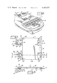
- FIG. 1 is a perspective view of a shorthand machine and a marking device including the features of the present invention.
- FIG. 2 is a top elevation view of the marking device illustrated in FIG. 1.
- FIG. 3 is a diagrammatic illustration of a side view of the marking device illustrated in FIG. 1.
- FIG. 4 is a cross-section taken at line 4--4 of FIG. 2.
- FIG. 5 is a top elevation view of the marking device with the cover and disposable marking instrument removed.
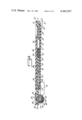
- FIG. 6 is a bottom elevation view of an elongate key of the marking device, showing in detail a marking instrument including a disposable cartridge.
- FIG. 7 is a side view of the disposable cartridge of FIG. 6.
- FIG. 8 is a bottom elevation view of the marking device, with the disposable cartridge removed.
- FIG. 1 of the drawing there is illustrated the marking device 2 of the present invention installed in a typical shorthand machine 3.
- a shorthand machine of this general type is more fully described in U.S. Pat. No. 2,319,273.
- Paper tape 6 is loaded in the machine 3 in the usual manner such that the paper tape 6 is carried and advanced by the platen 8 of the machine 3. Images are recorded on the tape 6 and the tape 6 is advanced around the platen 8 when the machine operator strikes the various keys of the keyboard 7 in the well known manner.
- the housing or marking device 2 defines and therefore, replaces the typical removable cover of the shorthand machine 3.
- the housing 2 comprises a substantially rectangular top plate 38 secured in spaced apart relationship to a complementary bottom or base plate 12 by screws 39 or other similar suitable bonding means.
- Tabs 10 depend from and project outwardly from the bottom side 11 of base plate 12 (FIG. 3), and engage the underside of the machine housing at 4 for securely mounting the marking device 2 in the machine 3.
- Pressure locking pad 9 made of resilient material such as rubber or the like is disposed between the top plate 38 and the bottom base plate 12 and engages the upperside of the machine housing 4, as shown in FIG.
- the marking device 2 is in the position normally occupied by a typical cover of a shorthand machine and may be readily removed and replaced by the machine operator in a similar manner, providing ready access to the components of the machine 3.
- the smooth surface of the cover is preserved, permitting use of the cover as a writing surface and facilitating storage of the machine 3.
- the housing 2 contains two elongate keys 14, 15 which are in horizontal, sliding relationship with the housing 2. It should be understood that only one elongate key 14 or 15 is needed to practice the invention, but two keys provide greater flexibility and usefulness. Each elongate key 14, 15 securely, though releasably, holds a marking instrument such as the disposable cartridge 40, which marks the paper tape 6.
- the elongate keys 14, 15 rest in channels 60, 61, respectively, in the base plate 12.
- the channels 60, 61 extend the length of the base plate 12 from the keyboard-adjusting end 18 to the platen-adjacent end 22.
- Each elongate key 14, 15 slides in a longitudinal manner within the respective channel 60, 61, between a fully retracted position A and a fully advanced position B, as in FIG. 2.
- two longitudinally spaced guideposts 63, 67 are positioned in each of the channels 60, 61 for tracking the keys 14, 15 and minimizing lateral movement thereof relative to the base plate 12.
- the underside 28 of each elongate key 14, 15 faces the base plate 12, and the top side 34 of each key 14, 15 faces the top plate 38 of the housing 2.
- a depending contact 30, projects downwardly from the underside 28 of each elongate key 14, 15 near the keyboard-adjacent end 18 thereof.
- the contact 30 engages the respective channel 60, 61 of the base plate 12.
- the two longitudinal slots, 26, 27 in each elongate key 14, 15 receive the guideposts 63, 67 respectively.
- each channel 60, 61 is provided with a lifter such as a "U"-shaped take-up spring 68.
- each take-up spring 68 is secured to the base plate 12 on post 63 near the platen-adjacent end of the respective channel 60, 61.
- the contact 30, spring 68 and ridges 31, 32 support the key 14, 15 in floating relationship within the housing 2 defined by top plate 38 and base plate 12.
- An upstanding post 64 is located on the base plate 12 intermediate of the channels 60, 61.
- Biasing means such as torsion spring 62 is mounted on the base plate 12 by placing the coil 69 of the spring 62 on the post 64.
- the opposite ends of the torsion spring 62 are attached to slots or openings 24 provided in each key 14, 15 for continuously urging the keys 14, 15 into the fully retracted position A, see FIG. 2.
- a dampening means consisting of a sponge rubber dampener 70 or the like is secured to each channel 60, 61 by two studs 65, 66 projecting upwardly from each channel 60, 61.
- Each of the studs 65, 66 secures a dampener 70 to the base plate 12 without limiting the compressibility of the dampener 70.
- Cavity 36 is located near the keyboard-adjacent end 18 of each key 14, 15, for receiving the dampener 70.
- the cavity 36 is longer than the dampener 70 and permits each key 14, 15 to be freely moved between the fully retracted and fully advanced positions. Upon retraction of the key 14, 15, the platen-adjacent end of the cavity 36 engages the dampener 70.
- each dampener 70 engages the respective key 14, 15 at the limits of its travel and acts as a positive stop while reducing the noise of operation by eliminating solid-to-solid contact.
- Finger pads 16 are provided at the keyboard-adjacent end 18 of each key 14, 15 and thus are in close proximity with the keyboard 7 of the shorthand machine 3.
- Each elongate key 14, 15 is engaged by pressing the respective finger pad 16, which can be engaged by the operator without completely removing his or her hands from the keyboard 7.
- the operator After selectively engaging one or both of the keys 14, 15, the operator need not reposition his or her hands in order to continue operation of the shorthand machine 3, thus saving time and enabling the operator to pay greater attention to the communication being recorded.
- Each elongate key 14, 15 has a forward cavity 20 near its platen-adjacent end 22.
- the forward cavity 20 receives the writing instrument of the device 2, such as disposable cartridge 40.
- the disposable cartridge 40 includes a "U"-shaped holder 41 having a top 58 and two sides 52.
- the top 58 of the holder 41 includes groove 56 which extends through each of the sides 52, as best shown in FIG. 7.
- the holder 41 and groove 56 define a live hinge 49 which enables the disposable cartridge 40 to be inserted in and ejected from the forward cavity 20 of the respective elongate key 14, 15.
- the live hinge 49 is in compression and securely, though releasably, holds the disposable cartridge 40 in position in the forward cavity 20.
- the forward cavity 20 is wider than the disposable cartridge 40 so that the cartridge 40 may be laterally adjusted relative to the machine platen 8.
- the operator may adjust the disposable cartridge 40 to mark the paper tape 6 at different points across its width.
- a roller 42 impregnated with ink 44 is rotatably mounted in the holder 41.
- sleeve 46 is securely fastened to the roller 42.
- the roller 42 and sleeve 46 are rotatably mounted on an axle 48 secured in the holder 41 through axle openings 50 provided in sides 52.
Landscapes
- Accessory Devices And Overall Control Thereof (AREA)
Abstract
Description
Claims (14)
Priority Applications (1)
| Application Number | Priority Date | Filing Date | Title |
|---|---|---|---|
| US06/257,777 US4363557A (en) | 1980-05-09 | 1981-04-27 | Marking device for shorthand machine |
Applications Claiming Priority (2)
| Application Number | Priority Date | Filing Date | Title |
|---|---|---|---|
| US14846180A | 1980-05-09 | 1980-05-09 | |
| US06/257,777 US4363557A (en) | 1980-05-09 | 1981-04-27 | Marking device for shorthand machine |
Related Parent Applications (1)
| Application Number | Title | Priority Date | Filing Date |
|---|---|---|---|
| US14846180A Continuation | 1980-05-09 | 1980-05-09 |
Publications (1)
| Publication Number | Publication Date |
|---|---|
| US4363557A true US4363557A (en) | 1982-12-14 |
Family
ID=26845884
Family Applications (1)
| Application Number | Title | Priority Date | Filing Date |
|---|---|---|---|
| US06/257,777 Expired - Lifetime US4363557A (en) | 1980-05-09 | 1981-04-27 | Marking device for shorthand machine |
Country Status (1)
| Country | Link |
|---|---|
| US (1) | US4363557A (en) |
Cited By (4)
| Publication number | Priority date | Publication date | Assignee | Title |
|---|---|---|---|---|
| US4439798A (en) * | 1981-09-14 | 1984-03-27 | Stenograph Corporation | Referencing device for digital data recorders |
| US5152617A (en) * | 1991-10-18 | 1992-10-06 | Xscribe Corporation | Stenographic machine having power driven note marker |
| US5280430A (en) * | 1991-06-27 | 1994-01-18 | Tariq Chaudhary | Computer-aided transcription system providing individualized electonic marking of stenographic records |
| US5466072A (en) * | 1992-01-17 | 1995-11-14 | Stenograph Corporation | Method and apparatus for recording and translating shorthand notes |
Citations (20)
| Publication number | Priority date | Publication date | Assignee | Title |
|---|---|---|---|---|
| US642759A (en) * | 1897-12-28 | 1900-02-06 | Rudolf Schade | Type-writing machine. |
| US1283198A (en) * | 1916-11-18 | 1918-10-29 | Nat Shorthand Machine Company | Shorthand-machine. |
| US1433453A (en) * | 1920-03-27 | 1922-10-24 | P Ricardo Guerrero | Ink-line-making attachment for typewriting machines |
| US1542455A (en) * | 1923-07-21 | 1925-06-16 | Howard Ebenezer | Shorthand machine |
| US1559771A (en) * | 1924-03-08 | 1925-11-03 | Padman Ruby Eva | Typewriter |
| US2176096A (en) * | 1934-11-03 | 1939-10-17 | Elizabeth D Oswald | Toy typewriter |
| US2199265A (en) * | 1938-07-09 | 1940-04-30 | Ncr Co | Porous metallic type |
| US2319273A (en) * | 1939-12-16 | 1943-05-18 | Stenographic Machines Inc | Stenographic machine |
| US2424073A (en) * | 1939-12-15 | 1947-07-15 | Ibm | Record feeding device |
| US2449126A (en) * | 1945-11-02 | 1948-09-14 | Wendell V Kirkpatrick | Mechanical shorthand writing means |
| US2745532A (en) * | 1952-09-18 | 1956-05-15 | Underwood Corp | Code typing means |
| US2777824A (en) * | 1950-06-27 | 1957-01-15 | Perma Stamp Products Corp | Process for making micro-reticulated material |
| US2823784A (en) * | 1955-01-14 | 1958-02-18 | Jack D Ambrose | Strip record signaling |
| US2847104A (en) * | 1953-08-03 | 1958-08-12 | Stenotype Grandjean Sa | Device for marking paper tapes in shorthand typewriters, calculating machines and the like |
| US3055297A (en) * | 1957-01-14 | 1962-09-25 | Johnson & Son Inc S C | Microporous synthetic resin material |
| US3213995A (en) * | 1963-11-20 | 1965-10-26 | James G Applin | Marker for a stenographic typewriter |
| US3404628A (en) * | 1966-07-11 | 1968-10-08 | Alves Photo Service Inc | Automatic marking device |
| US3964062A (en) * | 1974-12-09 | 1976-06-15 | Signal Laboratories, Inc. | Keyboard switch system |
| US4024943A (en) * | 1976-01-13 | 1977-05-24 | Steiner Dennis D | Marking apparatus for stenographic typewriter or the like |
| US4176973A (en) * | 1977-07-29 | 1979-12-04 | Gregory Stephen A | Stenotype tape marking attachment |
-
1981
- 1981-04-27 US US06/257,777 patent/US4363557A/en not_active Expired - Lifetime
Patent Citations (20)
| Publication number | Priority date | Publication date | Assignee | Title |
|---|---|---|---|---|
| US642759A (en) * | 1897-12-28 | 1900-02-06 | Rudolf Schade | Type-writing machine. |
| US1283198A (en) * | 1916-11-18 | 1918-10-29 | Nat Shorthand Machine Company | Shorthand-machine. |
| US1433453A (en) * | 1920-03-27 | 1922-10-24 | P Ricardo Guerrero | Ink-line-making attachment for typewriting machines |
| US1542455A (en) * | 1923-07-21 | 1925-06-16 | Howard Ebenezer | Shorthand machine |
| US1559771A (en) * | 1924-03-08 | 1925-11-03 | Padman Ruby Eva | Typewriter |
| US2176096A (en) * | 1934-11-03 | 1939-10-17 | Elizabeth D Oswald | Toy typewriter |
| US2199265A (en) * | 1938-07-09 | 1940-04-30 | Ncr Co | Porous metallic type |
| US2424073A (en) * | 1939-12-15 | 1947-07-15 | Ibm | Record feeding device |
| US2319273A (en) * | 1939-12-16 | 1943-05-18 | Stenographic Machines Inc | Stenographic machine |
| US2449126A (en) * | 1945-11-02 | 1948-09-14 | Wendell V Kirkpatrick | Mechanical shorthand writing means |
| US2777824A (en) * | 1950-06-27 | 1957-01-15 | Perma Stamp Products Corp | Process for making micro-reticulated material |
| US2745532A (en) * | 1952-09-18 | 1956-05-15 | Underwood Corp | Code typing means |
| US2847104A (en) * | 1953-08-03 | 1958-08-12 | Stenotype Grandjean Sa | Device for marking paper tapes in shorthand typewriters, calculating machines and the like |
| US2823784A (en) * | 1955-01-14 | 1958-02-18 | Jack D Ambrose | Strip record signaling |
| US3055297A (en) * | 1957-01-14 | 1962-09-25 | Johnson & Son Inc S C | Microporous synthetic resin material |
| US3213995A (en) * | 1963-11-20 | 1965-10-26 | James G Applin | Marker for a stenographic typewriter |
| US3404628A (en) * | 1966-07-11 | 1968-10-08 | Alves Photo Service Inc | Automatic marking device |
| US3964062A (en) * | 1974-12-09 | 1976-06-15 | Signal Laboratories, Inc. | Keyboard switch system |
| US4024943A (en) * | 1976-01-13 | 1977-05-24 | Steiner Dennis D | Marking apparatus for stenographic typewriter or the like |
| US4176973A (en) * | 1977-07-29 | 1979-12-04 | Gregory Stephen A | Stenotype tape marking attachment |
Cited By (4)
| Publication number | Priority date | Publication date | Assignee | Title |
|---|---|---|---|---|
| US4439798A (en) * | 1981-09-14 | 1984-03-27 | Stenograph Corporation | Referencing device for digital data recorders |
| US5280430A (en) * | 1991-06-27 | 1994-01-18 | Tariq Chaudhary | Computer-aided transcription system providing individualized electonic marking of stenographic records |
| US5152617A (en) * | 1991-10-18 | 1992-10-06 | Xscribe Corporation | Stenographic machine having power driven note marker |
| US5466072A (en) * | 1992-01-17 | 1995-11-14 | Stenograph Corporation | Method and apparatus for recording and translating shorthand notes |
Similar Documents
| Publication | Publication Date | Title |
|---|---|---|
| KR890006392A (en) | Ink-jet printhead to paper reference system | |
| JPS62166047U (en) | ||
| GB1582171A (en) | Inked ribbon cartridge | |
| US4363557A (en) | Marking device for shorthand machine | |
| EP0168193A1 (en) | Ink ribbon cassette | |
| US3952649A (en) | Check printer having ribbon cartridge | |
| US3401630A (en) | Record material feeding means | |
| JPS59114078A (en) | Thermal printer | |
| US4028771A (en) | Thin flat eraser and holder | |
| US4176973A (en) | Stenotype tape marking attachment | |
| US4027589A (en) | Portable imprinter | |
| US4325774A (en) | Correction label applying device for portable label printing machine | |
| US4595305A (en) | Ribbon cassette | |
| US4932577A (en) | Friction feed media driver for a sign plotter | |
| JPH09110184A (en) | Paper feed cassette | |
| US2863385A (en) | Printing machine | |
| US2642172A (en) | Erasing shield | |
| KR900011594A (en) | Carrier mover for printer | |
| JPH01149287U (en) | ||
| US6422771B1 (en) | Disposable ribbon cartridge for shorthand machine | |
| EP1857281B1 (en) | Type device, printer, and card case with printing function | |
| US4292894A (en) | Constant printing pressure mechanisms for label printing machine | |
| CN210234362U (en) | Adjustable ink box for flexible plate belt printing machine | |
| US2860876A (en) | Paper guide for printing press | |
| JPS5913081Y2 (en) | Ink ribbon cassette for printer |
Legal Events
| Date | Code | Title | Description |
|---|---|---|---|
| STCF | Information on status: patent grant |
Free format text: PATENTED CASE |
|
| MAFP | Maintenance fee payment |
Free format text: PAYMENT OF MAINTENANCE FEE, 4TH YEAR, PL 96-517 (ORIGINAL EVENT CODE: M170); ENTITY STATUS OF PATENT OWNER: LARGE ENTITY Year of fee payment: 4 |
|
| MAFP | Maintenance fee payment |
Free format text: PAYMENT OF MAINTENANCE FEE, 8TH YEAR, PL 96-517 (ORIGINAL EVENT CODE: M171); ENTITY STATUS OF PATENT OWNER: LARGE ENTITY Year of fee payment: 8 |
|
| FEPP | Fee payment procedure |
Free format text: PAYOR NUMBER ASSIGNED (ORIGINAL EVENT CODE: ASPN); ENTITY STATUS OF PATENT OWNER: LARGE ENTITY |
|
| MAFP | Maintenance fee payment |
Free format text: PAYMENT OF MAINTENANCE FEE, 12TH YEAR, LARGE ENTITY (ORIGINAL EVENT CODE: M185); ENTITY STATUS OF PATENT OWNER: LARGE ENTITY Year of fee payment: 12 |
|
| AS | Assignment |
Owner name: STENOGRAPH ACQUISITION CORP., ILLINOIS Free format text: ASSIGNMENT OF ASSIGNORS INTEREST;ASSIGNOR:STENOGRAPH CORPORATION;REEL/FRAME:007986/0472 Effective date: 19960215 |
|
| AS | Assignment |
Owner name: STENOGRAPH CORPORATION, ILLINOIS Free format text: CHANGE OF NAME;ASSIGNOR:STENOGRAPH ACQUISITION CORP.;REEL/FRAME:008307/0775 Effective date: 19960229 |
|
| AS | Assignment |
Owner name: STENOGRAPH, L.L.C., ILLINOIS Free format text: MERGER;ASSIGNOR:STENOGRAPH CORPORATION;REEL/FRAME:008535/0534 Effective date: 19970327 |