US4358792A - Precision screen elevating and control means for a projection television receiver - Google Patents
Precision screen elevating and control means for a projection television receiver Download PDFInfo
- Publication number
- US4358792A US4358792A US06/235,059 US23505981A US4358792A US 4358792 A US4358792 A US 4358792A US 23505981 A US23505981 A US 23505981A US 4358792 A US4358792 A US 4358792A
- Authority
- US
- United States
- Prior art keywords
- screen
- television
- receiver
- cabinet
- television system
- Prior art date
- Legal status (The legal status is an assumption and is not a legal conclusion. Google has not performed a legal analysis and makes no representation as to the accuracy of the status listed.)
- Expired - Fee Related
Links
- 230000003028 elevating effect Effects 0.000 title claims abstract description 54
- 230000004044 response Effects 0.000 claims abstract description 7
- 230000003287 optical effect Effects 0.000 claims description 25
- 230000003213 activating effect Effects 0.000 claims description 9
- 230000002441 reversible effect Effects 0.000 claims description 5
- 230000000087 stabilizing effect Effects 0.000 claims description 3
- 230000013011 mating Effects 0.000 claims 2
- 230000000994 depressogenic effect Effects 0.000 description 4
- 230000006870 function Effects 0.000 description 4
- 230000001360 synchronised effect Effects 0.000 description 3
- 230000004913 activation Effects 0.000 description 2
- 230000008901 benefit Effects 0.000 description 2
- 230000001419 dependent effect Effects 0.000 description 2
- 230000000881 depressing effect Effects 0.000 description 2
- 238000013461 design Methods 0.000 description 2
- 238000012986 modification Methods 0.000 description 2
- 230000004048 modification Effects 0.000 description 2
- 230000005236 sound signal Effects 0.000 description 2
- 238000004804 winding Methods 0.000 description 2
- 229920004943 Delrin® Polymers 0.000 description 1
- 235000014676 Phragmites communis Nutrition 0.000 description 1
- 239000006096 absorbing agent Substances 0.000 description 1
- 239000002131 composite material Substances 0.000 description 1
- 239000000356 contaminant Substances 0.000 description 1
- 238000010586 diagram Methods 0.000 description 1
- 230000004941 influx Effects 0.000 description 1
- 238000003780 insertion Methods 0.000 description 1
- 230000037431 insertion Effects 0.000 description 1
- 238000004519 manufacturing process Methods 0.000 description 1
- 230000007246 mechanism Effects 0.000 description 1
- 239000013618 particulate matter Substances 0.000 description 1
- 238000012545 processing Methods 0.000 description 1
- 230000003134 recirculating effect Effects 0.000 description 1
- 239000004065 semiconductor Substances 0.000 description 1
- 230000035939 shock Effects 0.000 description 1
- 230000002194 synthesizing effect Effects 0.000 description 1
- 238000012360 testing method Methods 0.000 description 1
- 238000012795 verification Methods 0.000 description 1
- 238000003466 welding Methods 0.000 description 1
Images


Classifications
-
- H—ELECTRICITY
- H04—ELECTRIC COMMUNICATION TECHNIQUE
- H04N—PICTORIAL COMMUNICATION, e.g. TELEVISION
- H04N9/00—Details of colour television systems
- H04N9/12—Picture reproducers
- H04N9/31—Projection devices for colour picture display, e.g. using electronic spatial light modulators [ESLM]
- H04N9/3141—Constructional details thereof
-
- H—ELECTRICITY
- H04—ELECTRIC COMMUNICATION TECHNIQUE
- H04N—PICTORIAL COMMUNICATION, e.g. TELEVISION
- H04N5/00—Details of television systems
- H04N5/74—Projection arrangements for image reproduction, e.g. using eidophor
- H04N5/7475—Constructional details of television projection apparatus
- H04N2005/7483—Constructional details of television projection apparatus for colour television
Definitions
- This invention concerns television systems, and is particularly directed to a system in which a rear projection screen, storable in the system cabinet, is elevatable for viewing.
- An ultra-compact, jack-in-the-box projection television receiver comprises cabinet means for enclosing components of the receiver and lid means hinged at the back of the cabinet.
- the receiver has vertically arranged, elevatable rear projection screen means selectively storable in the cabinet.
- Means are included for lifting the lid and elevating the screen from a first, receiver-inoperable position wherein the screen is stored in the cabinet and the receiver is substantially as compact as a conventional, large-screen console television receiver, to a second, elevated receiver-operable position wherein the screen is emerged from the cabinet.
- the receiver When the screen is in the second elevated receiver-operable position, the receiver is capable of displaying an image with an area greater than three times the image area on the conventional console television receiver.
- An image source means for forming a television image includes stationary image projection means permanently stored in the aforedescribed cabinet for projecting an aerial image of the television image along a path folded by optical path folding means onto the aforedescribed screen.
- the projection can take place when the screen is erected and located a predetermined image projection distance from the image source means.
- the optical path is extended to a length equal to the predetermined image projection distance, and the projection image is coincident with the screen.
- a screw-propelled mechanism known in the manufacturing art provides for lifting and lowering printed circuit boards between an upper electrical test station and a lower insertion/removal station. Means are provided for detecting the presence of boards at either station and reversing the direction of traverse.
- the present invention provides for elevating the screen from a first receiver-inoperable position wherein the screen is lowered and stored in the cabinet and the receiver is ultra-compact, to an elevated receiver-operable position wherein the screen is emerged from the cabinet.
- FIGS. 1A, and 1B and 1C are oblique views in perspective of a projection television receiver depicting, respectively, a first receiver-inoperable position, and a second receiver-operable position wherein a rear-projection screen is elevated from the receiver cabinet;
- FIG. 2 is a schematic view of the components of the optical path of the receiver when the screen is elevated, in relation to the receiver cabinet, shown as an outline;
- FIG. 3 is an oblique view in perspective depicting the receiver with screen elevated and with the receiver cabinet partially cut away to show major components;
- FIGS. 4A and 4B are views in elevation wherein the receiver cabinet is cut away to show the relationship of major receiver components with the elevating means according to the invention
- FIG. 5A is a view in perspective with the front of the receiver cabinet cut away to show details of a preferred embodiment of the precision elevating means according to the invention
- FIG. 5B is a view similar to FIG. 5A but with the floor of the cabinet shown as being removed to depict additional details of the precision elevating means according to the invention.
- FIG. 6 is a view in perspective of the essentials of another embodiment of screen elevating means according to the invention.
- FIG. 1A An ultra-compact, jack-in-the-box projection television receiver 10 according to the invention described and claimed in referent copending application Ser. No. 228,434 is shown by FIG. 1A.
- the receiver comprises cabinet means 12 for enclosing the components of the receiver.
- Cabinet 12 includes lid means 14 attached to the back of the cabinet and pivoted by a hinge 16 which may comprise a piano hinge, for example.
- the lid 14 may have an overhanging control panel cover 18 for covering a receiver control panel.
- Grilled aperture ports 20 provide for audio emission from concealed speakers of, for example, a stereo sound system.
- lid 14 is shown as being raised and elevatable rear projection screen means 24 with enclosing frame is shown as being emerged from cabinet means 12.
- the rear projection viewing screen 24 is shown as being vertically arranged for displaying a television image.
- Control panel 25 which may include all standard front panel controls such as controls for channel selection, audio volume, and various chromatic controls, and control means such as control means according to the invention for elevating and lowering screen 24, is exposed by the raising of control panel cover 18 when lid 14 is raised.
- Control panel cover 18 may be hingedly dependent from lid 14, as indicated. Control panel cover 18 is described and claimed in referent copending application Ser. No. 259,333.
- Remote control means 23, indicated in FIG. 1C as being a hand-held unit may be linked to control circuits in receiver 10 by acoustic or infra-red means, for example, and may provide controls similar to those located on control panel 25.
- Image source means 26 for forming a television image is permanently enclosed in a lower portion the cabinet as indicated by the bracket, and is depicted as being mounted on the floor 27 of cabinet 12.
- Image source means 26 is indicated as comprising three cathode ray tubes 28.
- the cathode ray tubes 28 may each develop, respectively, a red, green, or blue image for projecting in conjunction with stationary image projection means 30 an aerial image of a television image formed by image source means 26.
- the image is projected along a folded optical path 34 onto screen 24 when the optical path is erected and screen 24 is located at a predetermined image projection distance from image source means 26.
- a television image 32 is depicted in FIG. 2 as being formed on the cathodoluminescent screen of one of the cathode ray tubes.
- the image source means 26 includes first mirror means 36 which provides for receiving the aerial image and reflecting the image upwardly.
- the image source means 26 is fully described and claimed in referent copending application Ser. No. 314,591.
- the elevatable unitary optical assembly 22 indicated by the bracket in FIG. 2 includes rear projection screen 24 for displaying the projected television image 32.
- a second mirror means 38 provides for receiving the image reflected from first mirror 36, and is arranged to reflect the image forwardly toward screen 24.
- Rigid, box-like shroud means 40 supports screen 24 and the second mirror 38 to form the unitary optical assembly 22.
- Shroud 40 also provides for shielding mirror 38 and the rear surface 42 of screen 24 from image-contrast-reducing ambient light.
- Cabinet extension 43 provides additional space for enclosing shroud 40 when the unitary optical assembly 22 is stored. The unitary optical assembly 22 is described and fully claimed in referent copending application Ser. No. 238,861.
- the angular orientations of second mirror 38 are made adjustable to ensure that the projection image, which follows the folded optical path 34, can be kept in coincidence with screen 24.
- the adjustment means 46 are conveniently made accessible by their location on the side of shroud 40, as depicted in FIG. 2. The adjustment means are fully described and claimed in referent copending application Ser. No. (D4282).
- FIG. 4A shows the elevatable unitary optical assembly 22, which includes screen 24, second mirror 38 and shroud 40, in a first receiver-inoperable position 44 wherein the assembly and screen means 24 is stored in cabinet 12.
- Means according to the present invention are provided for raising lid 14 and elevating unitary optical assembly 22 to an elevated receiver-operable position wherein the unitary optical assembly 22 is emerged from cabinet 12, as depicted by FIGS. 1B, 3 and 4B.
- the optical path is thus extended to a length equal to the predetermined image projection distance and the projection image is coincident with the screen 24.
- FIGS. 5A and 5B A preferred embodiment of the precision elevating means according to the invention for elevating and lowering unitary optical assembly 22 and rear-projection screen 24 is shown by FIGS. 5A and 5B.
- Shroud 40 is shown as cut away at the left-hand side of FIG. 5A to show details of the precision elevating means according to the invention.
- a substantially identical, mirror-image assembly having the same elevating function is located on the opposite side of cabinet 12. The use of the plural form in part designation in the following paragraph indicates that there is an identical member at the opposite end of the cabinet having the same function.
- At least two vertically oriented, vertically stabilized screen means 50 shown as being four screen means in this preferred embodiment, provide for elevating and lowering screen 24.
- Screw means 50 may, by way of example, comprise triple-lead, rolled threads having a diameter of about five-eighths of an inch, and a length of about thirty-one inches. Thread pitch is about eight threads per inch.
- Associated screw-follower means 51 are attached to shroud mounting members 52 to which shroud 40 is in turn attached.
- Thrust bearings 54 provide for receiving the vertical thrust of screw means 50.
- Shroud 40 may be attached to the shroud mounting members 52 by machine screws.
- a plurality of vertical guide rods 53 are enclosed by linear motion bearings 55, attached in turn to shroud mounting members 52.
- Bearings 55 are indicated as being located behind members 52, as indicated by the dash line configuration.
- Bearings 55 may be of the recirculating ball bearing type, for example.
- the linear motion bearings 55 may comprise sleeve-like sections of Delrin (R) attached to the associated shroud mounting member 52, and having a tight-tolerance hole therethrough for accepting the associated guide rods 53.
- Guide rods 53 provide for stabilizing unitary optical assembly 22 as it is raised and lowered by the precision elevating means according to the invention.
- the mountings attached to the shroud mounting members 52, and which retain the screw follower means 51, are designed to allow the screw follower means to "float"; that is, to move transversely with little restriction.
- shroud mounting members 52, and the unitary optical assembly 22 attached thereto are vertically stabilized solely by the guide rods 53 during the reciprocation of the screen 24.
- the floating mounts effectively prevent binding during screen reciprocation, and help ensure vertical stability of the screen 24 during its raising and lowering.
- Screw means 50 are caused to rotate in unison by power train means which may be of the design indicated in FIG. 5B.
- the power train in the preferred embodiment depicted includes four screw-rotating pulleys 56, 58, 60 and 62, each of which is keyed to the associated screw means 50. It will be observed that the screw means located in the rear of the cabinet 12 are caused to rotate in unison with the screw means located at the front of the cabinet by synchronous belt means 64 and 66, which engage a second tier 58A and 60A of screw rotating pulleys 58 and 60, respectively.
- the second tiers 58A and 60A of screw rotating pulleys 58 and 60 are in turn caused to rotate in unison by synchronous drive belts 68 and 70, which are driven in turn by two-tier synchronous pulley 72 keyed to the rotating output shaft of drive motor 74. Except for drive motor 74, the entire power train assembly is preferably located beneath the floor 62 of cabinet 12, as indicated by FIG. 5B.
- Motor 74 is preferably of a type that provides twenty inch/pounds of starting and running torque.
- Motor 74 may be of the kind supplied by von Weise Gear Comany, St. Louis, Missouri under the designation type No. VO3300AA31, or an equivalent. Power consumption of this motor is 150-200 watts when supplied with 24 volts direct current. Speed of rotation may be, for example, about 250 rpm.
- a heat-sensitive relay switch preferably provides for thermal cut out upon overload.
- a reversible permanent magnet motor having similar operating specifications, but operating from 107 volts average direct current (120 VAC rectified), and consuming only 85-100 watts, can as well be used.
- This motor can be of the type manufactured by von Weise Gear Company under the designation Type No. VO3300AB31, or an equivalent. Power consumption of this motor is in the range of 85-100 watts.
- Projection television receiver 10 also includes a television system having an ON control mode for providing television sound and television images for display on screen 24 when screen 24 is emerged from cabinet 12.
- the television system also includes an OFF control mode for turning off the aforesaid sound and images.
- the television system 76 is indicated highly schematically by the block in the center of the cabinet toward the back wall in FIG. 5.
- Television system 76 should be considered as having well-known-in-the-art television components and stages including a standard tuner, video if amplifiers, video detector, a luminance channel, sweepcircuits, and in color receivers, a chrominance channel, all of which cooperate to act as a television image source means 26 in conjunction with one or more cathode ray tubes 28.
- television system 76 preferably has a tuning system which includes a microcomputer, as will be described.
- the audio signal processing means of the television system 76 provides for detecting the audio component of the composite video signal following the video if amplifier stage.
- the detected audio signal is amplified by an audio amplifier means which in turn drives one or more speakers (not shown).
- the precision elevating means includes control means coupled to the elevating means and to the television system 76 for sensing the position of screen 24 and obstructions to the screen in its reciprocation, and correlatively controlling the elevating means and the ON/OFF control modes of television system 76 in response thereto.
- the presence of obstructions is manifested by increased resistance to screen elevating and lowering.
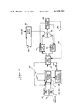
- the control of television system 76, and the lifting and lowering of screen 24 is preferably initiated either by activating controls on the control panel 25 of receiver 10, or the keypad on the hand-held control unit 23 located remotely from receiver 10 shown in FIG. 6, which is a functional block diagram of the control means according to the invention.
- Screen control means 78 may comprise, by way of example, a push-button switch 80 designated OFF/ON and having an upwardly oriented arrowhead, which provides for turning the television system 76 on and elevating screen 24.
- Screen control means 78 also may comprise, by way of example, a push-button 82 designated SCREEN with a downwardly oriented arrowhead for lowering screen 24.
- FIG. 5A The physical location of the various means for sensing the position of screen 24, whether it is in the raised position, lowered position, or in reciprocation therebetween, is shown by FIG. 5A wherein the sensing means 98, 104, 106, and 108 are depicted as lever-actuated switches.
- the sensing means may comprise, by way of example, single-pole, double-throw snap-action switches either normally closed or normally open and actuated by levers extending therefrom for detecting the position or passing of one or both shroud mounting members 52 to which shroud 40 and associated screen 24 is attached.
- the sensing means could as well comprise magnetically activated reed switches or other proximity switch devices that provide for making or breaking electrical circuits. Additionally, some or all of the sensing means 98, 104, 106 and 108, shown as being positioned at the left end of cabinet 12, could as well be located at the opposite end of the cabinet.
- elevating screen 24 from a lowered, receiver-inoperable position wherein screen 24 is stored in cabinet 12, and a raised, receiver-operable position wherein screen 24 is emerged from cabinet 12 for display of television pictures, is initiated by depressing OFF/ON pushbutton switch 80.
- a microcomputer 88 which is part of the tuning system, sends a pulse to the switching logic section 90, which determines that the screen 24 is in the stored position.
- a pulse is sent to the screen-up relay 92 by logic section 90, closing the relay contacts to supply power to motor 74.
- the forward rotation of motor 74 activates the aforedescribed power train, resulting in the elevating of screen 24 to the fully raised position.
- SCREEN pushbutton switch 82 depressing SCREEN pushbutton switch 82.
- the activation of SCREEN switch 82 causes the microcomputer 88 to send a pulse to the switching logic section 90, wherein a determination is made that screen 24 is in raised position.
- Screen down relay 94 is then activated, resulting in a reversal of the rotation of motor 74 and the lowering of screen 24. Concurrently, television system 76 is turned off.
- the tuning system of which the microcomputer 88 is a part, is an electronic, microcomputer-controlled television tuning system capable of acquiring channels offset by as much as 3.25 MHz from the designated frequency while also being able to accurately tune in channels operating at the designated frequency.
- the microcomputer looks at AFC discriminator information from which local oscillator tuning voltage direction is determined.
- the tuning voltage is then stepped by the microcomputer in small frequency increments which vary from 28 KHz for channel 2 to 80 KHz for channel 80 in the direction of the desired frequency until the center video carrier frequency is passed.
- the tuning voltage is then returned to the preceding step to which frequency the receiver is then locked.
- the microcomputer is a four-bit, E/D MOS unit with a read-only memory, a random access memory, an arithmetic logic unit, input/output ports, and a clock generator, all on a single semiconductor chip.
- the microcomputer chip is one of the MN1400 series basic design as manufactured by Matshushita Electronics Corporation, and especially modified for the referent '732 application.
- Switching logic section 90 is an elementary logic unit that responds to the means for sensing the raised and lowered positions of screen 24 for stopping and reversing motor 74 at the respective positions. It responds to pulses from the microcomputer and emits command logic pulses, and also has other elementary logic circuit functions as will be described.
- Screen up relay 92 and screen down relay 94 provide for control of the direction of rotation of motor 74.
- Switching logic section 90 determines the proper direction of rotation of motor 74 and activates either screen up relay 92 or screen down relay 94.
- Relays 92 and 94 are electrically latched and are activated upon receiving a latching pulse, and remain latched until an unlatching pulse is received.
- Means are provided for sensing the proximity of screen 24 to the raised position and controlling the speed of motor 24 for slowing the rate of elevating whereby screen 24 does not come to an abrupt stop.
- the slowing of motor 74 is accomplished by reducing the voltage to motor 74 from the power supply 96.
- Power supply 96 may comprise, for example, a transformer for reducing 120 VAC to 24 VAC, and a four-diode bridge circuit to provide full-wave rectification for supplying 24 VDC for motor 74 operation.
- Sensing means 98 indicated as comprising a normally closed switch, is depicted in FIG. 5 as being located near the top of the excursion of shroud mounting member 52.
- sensing means 98 activates, for example, a lever extending from sensing means 98.
- sensing means switch 98 which are in series connection with one leg of the full-wave rectifier, open.
- the output of power supply 96 is effectively halved to 12 VDC, for example, and motor 74 rotates at approximately half speed, thus slowing the rate of rise of screen 24.
- the stopping of screen 24 is preferably further gentled by spring shock absorber means 100, depicted as being located at the limit of topmost excursion of shroud mounting members 52.
- Power supply 96 also supplies 12 VDC for operation of relays 92 and 94 and other components of the control means.
- power supply 96 is designed to rectify 120 VAC to supply 107 volts average direct current for full-speed operation of the motor, and about 55 volts average direct current for operation of the motor at half speed.
- motor 74 is preferably programmed to run at half speed because the weight of the unitary optical assembly 22, which includes the screen, accelerates the rate of lowering appears to the eye to be about equal to the rate of rise of the screen under full motor speed.
- Over-current sensor 102 provides for sensing an obstruction to the elevating and lowering of screen 24, manifested by increased resistance to elevating and lowering, and in conjunction with the control means, provides for turning off motor 74 and television system 76 in response.
- Sensor 102 operates by sensing the magnitude of the current drawn by motor 74.
- Sensor 102 may comprise, for example, a resistor (not shown) in series with the winding of motor 74.
- a separate bipolar transistor switch normally in saturation is in series with each of the relay coil windings of relays 92 and 94.
- Over-current sensor 102 also provides for sensing the raised and lowered positions of screen 24, and for stopping screen excursion and reversing motor 74 at the upper and lower limit positions by a signal sent through signal path 103.
- Switching logic section 90 provides for selecting the proper relay, whether screen up relay 92 or screen down relay 94, when either limit position is reached.
- Means are provided for sensing the raising of screen 24 from the lowered position and activating the ON control mode of the television system 76, such that when screen 24 attains the raised position, television pictures will be instantly seen and sound will be heard.
- the microcomputer 88 also sends a turn-on pulse to the TV system 76.
- the normally closed contacts of switch 104 still in closed position provide for disabling the raster circuit and muting the sound circuits of the television system 76.
- switch 104 opens, and the raster and sound are restored so that sound is heard and pictures are seen the instant the screen attains the raised position.
- the time required to elevate screen 24 to the raised position is adequate for the filaments of the cathode ray tubes 28 to reach operating temperature.
- switch 104 is indicated as being located at the top of the excursion of screen 24, along with sensing means switches 106 and 108.
- One or more of the switches can as well be mounted at the sides of the path of reciprocation of shroud mounting means 52.
- Means are provided for detecting the raised position of screen 24, and in conjunction with control means, providing for the OFF/ON control of the television system 76 only by the OFF/ON control means.
- the benefit is that the television system 76 can be turned on or off by means of the OFF/ON switch 80 without going through the cycle of lowering and raising screen 24. This is accomplished by means of normally closed switch 106.
- sensor 102 detects the overcurrent condition and unlatches the screen relay 92 to stop motor 74.
- Switch 106 opens concurrently to disable operation of the screen elevating function of OFF/ON switch 80, so switch 80 controls only the OFF/ON modes of television system 76.
- Means are provided for detecting the lowered position of screen 24, and in conjunction with the control means, providing for turning off motor 74 so screen 24 does not rise during an automatic programming mode.
- the user may program the receiver to turn on at a certain time. If the user is absent and the screen is stored in cabinet 12, the receiver will not turn on and the screen will not emerge although the receiver is in the automatic programming mode.
- This disabling is accomplished by sensing means 108, which has been noted as being located at the top of the reciprocation of screen 24.
- the lowering of the screen causes the normally closed contacts of switch 108 to open.
- the opening of the contacts is noted by the microcomputer 88 which had been previously programmed for automatic programming. In this case, the ON control mode of the television system 76 is disabled and the screen will not emerge.
- Means are provided for sensing the lowered position of screen 24 and activating the OFF control mode of television system 76 so the television system cannot come on when screen 24 is stored. (It is to be noted that the television system is turned on, but the receiver is without picture and sound when screen 24 begins elevating, as described heretofore). As screen 24 lowers for storing and reaches the lowered position, the over-current drawn by motor 74 is detected by over-current sensor 102. A signal pulse is sent to the switching logic section 90 through signal path 103 and switch 106, noted as being normally closed except when screen 24 is in the raised position. A signal pulse is sent to the microcomputer 88 through path 109, which in turn places and holds the television system 76 in the OFF control mode until OFF/ON switch 80 is again depressed.
- Means are provided to prevent the lowering of screen 24 should the television system 76 not turn off when the SCREEN (down) 80 is depressed.
- the application of 120 VAC power to the components of television system 76 is through the normally closed contacts of a latching relay switch (not shown) under the control of the microcomputer 88. Activating OFF/ON pushbutton switch 80 causes microcomputer 88 to latch the relay on, routing 120 volts to the other television components.
- the precision elevating means provides for raising and lowering lid 14.
- a track 112 (please refer to FIG. 4B) is located on the outside surface of the shroud 40.
- a track-follower means (not shown) is attached to the inner surface of lid 14. As shroud 40 is elevated and lowered, the track follower rides on the track 112 so that there is no friction between lid 14 and shroud 40 during elevating and lowering of screen 24. Also, the lid-lifting means prevents the lid 14 from falling backwards as the shroud 40 is elevated. Further, the track is contoured to provide an initial quick rise of the lid as the screen emerges from the cabinet 12.
- the lid lifting means is described and claimed in referent copending application Ser. No. 277,493.
- the elevating of screen 24 from a stored, first receiver-inoperable position wherein the unitary optical assembly 22 and associated screen 24 is emerged from cabinet 12 results in a large influx of air into cabinet 12, and when screen 24 is lowered for storing, a large efflux of air.
- the volume of air entering or leaving cabinet 12 is considerable--about six cubic feet--and the rate of flow is about twenty-four cubic feet per minute on the basis that fifteen seconds is allotted for the full excursion of the screen 24 out of, or into, cabinet 12.
- a series of capacious vents 114 are provided in cabinet 12, preferably in the floor 27 of cabinet 12, as indicated in FIG. 4A.
- a vent 118 may also be provided on the slanted upper surface of shroud 40, as indicated.
- Exemplary dimensional heighth (H), width (W) and depth (D) values of the cabinet 12 of the projection television receiver 10 are listed as follows. It is to be recognized that the values are by way of example only, and are intended to be in no way limiting. The dimensional values are in inches.
Landscapes
- Engineering & Computer Science (AREA)
- Multimedia (AREA)
- Signal Processing (AREA)
- Transforming Electric Information Into Light Information (AREA)
Abstract
Description
Claims (6)
Priority Applications (1)
| Application Number | Priority Date | Filing Date | Title |
|---|---|---|---|
| US06/235,059 US4358792A (en) | 1981-02-17 | 1981-02-17 | Precision screen elevating and control means for a projection television receiver |
Applications Claiming Priority (1)
| Application Number | Priority Date | Filing Date | Title |
|---|---|---|---|
| US06/235,059 US4358792A (en) | 1981-02-17 | 1981-02-17 | Precision screen elevating and control means for a projection television receiver |
Publications (1)
| Publication Number | Publication Date |
|---|---|
| US4358792A true US4358792A (en) | 1982-11-09 |
Family
ID=22883932
Family Applications (1)
| Application Number | Title | Priority Date | Filing Date |
|---|---|---|---|
| US06/235,059 Expired - Fee Related US4358792A (en) | 1981-02-17 | 1981-02-17 | Precision screen elevating and control means for a projection television receiver |
Country Status (1)
| Country | Link |
|---|---|
| US (1) | US4358792A (en) |
Cited By (16)
| Publication number | Priority date | Publication date | Assignee | Title |
|---|---|---|---|---|
| US4400736A (en) * | 1981-06-26 | 1983-08-23 | Zenith Radio Corporation | Lid raising means for a jack-in-the-box projection television receiver |
| US4417273A (en) * | 1982-01-04 | 1983-11-22 | Kloss Video Corporation | Video projection system |
| US4479144A (en) * | 1981-05-01 | 1984-10-23 | Sony Corporation | Video projecting apparatus |
| FR2544675A1 (en) * | 1983-04-22 | 1984-10-26 | Agar Gerard | Directable compactable cinematographic back-projection device with sound, which can be fitted to motor vehicles |
| US4556913A (en) * | 1984-01-13 | 1985-12-03 | Rca Corporation | Apparatus for preventing virtual images in projection television receivers |
| EP0433469A1 (en) * | 1988-06-23 | 1991-06-26 | Bke Bildtechnisches Konstruktions- Und Entwicklungsbüro Inh. Ernst Stechemesser | Video projection arrangement with a swivel-lift mechanism |
| US5138462A (en) * | 1988-01-27 | 1992-08-11 | Bang & Olufsen A/S | TV-set having screen covering means |
| US5345153A (en) * | 1993-03-15 | 1994-09-06 | Michael Vaught | Ornamental closure |
| US6612670B2 (en) * | 2000-06-20 | 2003-09-02 | Yu-An Liu | Elevated screen |
| US6709114B1 (en) | 2000-01-27 | 2004-03-23 | Thomson Licensing S.A. | Spherical mounting system for three axis adjustment of light projector assembly in a projection television |
| US20050248731A1 (en) * | 2004-05-08 | 2005-11-10 | Young-Jun Jung | Projection apparatus |
| US20100144234A1 (en) * | 2008-12-05 | 2010-06-10 | Silverlit Toys Manufactory Ltd. | Storage housing for a remote controlled toy |
| CN110908233A (en) * | 2019-12-06 | 2020-03-24 | 四川长虹电器股份有限公司 | Control system and method for integrated cabinet of ultra-short-focus projector |
| CN114125518A (en) * | 2020-06-29 | 2022-03-01 | 海信视像科技股份有限公司 | a display device |
| CN114545712A (en) * | 2020-11-27 | 2022-05-27 | 青岛海信激光显示股份有限公司 | Start-up control method and shutdown control method of projection equipment |
| CN114545711A (en) * | 2020-11-27 | 2022-05-27 | 青岛海信激光显示股份有限公司 | Start-up control method and shutdown control method of projection equipment |
Citations (1)
| Publication number | Priority date | Publication date | Assignee | Title |
|---|---|---|---|---|
| US4245256A (en) * | 1978-09-20 | 1981-01-13 | Sony Corporation | Video projector and mounting structure |
-
1981
- 1981-02-17 US US06/235,059 patent/US4358792A/en not_active Expired - Fee Related
Patent Citations (1)
| Publication number | Priority date | Publication date | Assignee | Title |
|---|---|---|---|---|
| US4245256A (en) * | 1978-09-20 | 1981-01-13 | Sony Corporation | Video projector and mounting structure |
Cited By (19)
| Publication number | Priority date | Publication date | Assignee | Title |
|---|---|---|---|---|
| US4479144A (en) * | 1981-05-01 | 1984-10-23 | Sony Corporation | Video projecting apparatus |
| US4400736A (en) * | 1981-06-26 | 1983-08-23 | Zenith Radio Corporation | Lid raising means for a jack-in-the-box projection television receiver |
| US4417273A (en) * | 1982-01-04 | 1983-11-22 | Kloss Video Corporation | Video projection system |
| FR2544675A1 (en) * | 1983-04-22 | 1984-10-26 | Agar Gerard | Directable compactable cinematographic back-projection device with sound, which can be fitted to motor vehicles |
| US4556913A (en) * | 1984-01-13 | 1985-12-03 | Rca Corporation | Apparatus for preventing virtual images in projection television receivers |
| US5138462A (en) * | 1988-01-27 | 1992-08-11 | Bang & Olufsen A/S | TV-set having screen covering means |
| EP0433469A1 (en) * | 1988-06-23 | 1991-06-26 | Bke Bildtechnisches Konstruktions- Und Entwicklungsbüro Inh. Ernst Stechemesser | Video projection arrangement with a swivel-lift mechanism |
| US5485068A (en) * | 1993-03-15 | 1996-01-16 | Vaught; Michael | Multiple plug-in programmable sensory device system |
| US5345153A (en) * | 1993-03-15 | 1994-09-06 | Michael Vaught | Ornamental closure |
| US6709114B1 (en) | 2000-01-27 | 2004-03-23 | Thomson Licensing S.A. | Spherical mounting system for three axis adjustment of light projector assembly in a projection television |
| US6612670B2 (en) * | 2000-06-20 | 2003-09-02 | Yu-An Liu | Elevated screen |
| US20050248731A1 (en) * | 2004-05-08 | 2005-11-10 | Young-Jun Jung | Projection apparatus |
| US7175282B2 (en) * | 2004-05-08 | 2007-02-13 | Samsung Electronics Co., Ltd. | Projection apparatus having separated optical engine and driving circuit |
| US20100144234A1 (en) * | 2008-12-05 | 2010-06-10 | Silverlit Toys Manufactory Ltd. | Storage housing for a remote controlled toy |
| US8075364B2 (en) * | 2008-12-05 | 2011-12-13 | Silverlit Limited | Storage housing for a remote controlled toy |
| CN110908233A (en) * | 2019-12-06 | 2020-03-24 | 四川长虹电器股份有限公司 | Control system and method for integrated cabinet of ultra-short-focus projector |
| CN114125518A (en) * | 2020-06-29 | 2022-03-01 | 海信视像科技股份有限公司 | a display device |
| CN114545712A (en) * | 2020-11-27 | 2022-05-27 | 青岛海信激光显示股份有限公司 | Start-up control method and shutdown control method of projection equipment |
| CN114545711A (en) * | 2020-11-27 | 2022-05-27 | 青岛海信激光显示股份有限公司 | Start-up control method and shutdown control method of projection equipment |
Similar Documents
| Publication | Publication Date | Title |
|---|---|---|
| US4358792A (en) | Precision screen elevating and control means for a projection television receiver | |
| US6697123B2 (en) | Adaptive picture-in-picture | |
| US6519416B1 (en) | Magnet recording/reproducing apparatus with video camera, suited for photorecording without attending camera operator | |
| US4491872A (en) | Ultra-compact projection television receiver | |
| US5329376A (en) | VCR control of a cable converter unit with active signal detection | |
| US4903129A (en) | Audio signal section apparatus | |
| US6211921B1 (en) | User interface for television | |
| US20010013856A1 (en) | Video display apparatus and method of preventing inadvertent switch-off of light source therein | |
| US20070115435A1 (en) | Projector and method of projecting an image having multiple image sizes | |
| JP2004521553A (en) | Smart picture-in-picture | |
| WO2011128829A2 (en) | Method for displaying a video stream according to a customised format | |
| US5408284A (en) | Remote-controlled slide projector | |
| US5473371A (en) | Window generating apparatus for use in a video camera | |
| US6833879B1 (en) | Image projection in television off position | |
| EP0680212B1 (en) | Image input device for inputting images of a plurality of subjects by switching image pickup direction | |
| US4935819A (en) | Picture-width-adaptable television receiver | |
| US4349845A (en) | Control panel cover for projection television receiver | |
| GB2263035A (en) | An ir led assembly for vcr control of a cable converter unit | |
| KR20020059545A (en) | Method for Controlling Display of TV | |
| KR940010173B1 (en) | Curtain function control device of video camera | |
| US20250291007A1 (en) | MRI Bore Projector System | |
| JPH05103376A (en) | Remote control device | |
| JP2003009041A (en) | LCD projector | |
| JPS55140373A (en) | Automatic focus adjustment unit of video camera | |
| WO1998039926A1 (en) | Television system |
Legal Events
| Date | Code | Title | Description |
|---|---|---|---|
| AS | Assignment |
Owner name: ZENITH RADIO CORPORATION, 1000 MILWAUKEE AVENUE, G Free format text: ASSIGNMENT OF ASSIGNORS INTEREST.;ASSIGNORS:DOMOLECZNY, JAMES D.;LOH, RAYMOND D. Y.;MANSKE, HANS E.;AND OTHERS;REEL/FRAME:004011/0920 Effective date: 19810212 |
|
| MAFP | Maintenance fee payment |
Free format text: PAYMENT OF MAINTENANCE FEE, 4TH YEAR, PL 96-517 (ORIGINAL EVENT CODE: M170); ENTITY STATUS OF PATENT OWNER: LARGE ENTITY Year of fee payment: 4 |
|
| MAFP | Maintenance fee payment |
Free format text: PAYMENT OF MAINTENANCE FEE, 8TH YEAR, PL 96-517 (ORIGINAL EVENT CODE: M171); ENTITY STATUS OF PATENT OWNER: LARGE ENTITY Year of fee payment: 8 |
|
| AS | Assignment |
Owner name: FIRST NATIONAL BANK OF CHICAGO, THE Free format text: SECURITY INTEREST;ASSIGNOR:ZENITH ELECTRONICS CORPORATION A CORP. OF DELAWARE;REEL/FRAME:006187/0650 Effective date: 19920619 |
|
| AS | Assignment |
Owner name: ZENITH ELECTRONICS CORPORATION Free format text: RELEASED BY SECURED PARTY;ASSIGNOR:FIRST NATIONAL BANK OF CHICAGO, THE (AS COLLATERAL AGENT).;REEL/FRAME:006243/0013 Effective date: 19920827 |
|
| FEPP | Fee payment procedure |
Free format text: MAINTENANCE FEE REMINDER MAILED (ORIGINAL EVENT CODE: REM.); ENTITY STATUS OF PATENT OWNER: LARGE ENTITY |
|
| LAPS | Lapse for failure to pay maintenance fees | ||
| FP | Lapsed due to failure to pay maintenance fee |
Effective date: 19941104 |
|
| STCH | Information on status: patent discontinuation |
Free format text: PATENT EXPIRED DUE TO NONPAYMENT OF MAINTENANCE FEES UNDER 37 CFR 1.362 |