US4357190A - Method and apparatus for manufacturing non-round plastic tubing - Google Patents
Method and apparatus for manufacturing non-round plastic tubing Download PDFInfo
- Publication number
- US4357190A US4357190A US06/162,006 US16200680A US4357190A US 4357190 A US4357190 A US 4357190A US 16200680 A US16200680 A US 16200680A US 4357190 A US4357190 A US 4357190A
- Authority
- US
- United States
- Prior art keywords
- tubing
- terminal edge
- generally
- edge areas
- longitudinally
- Prior art date
- Legal status (The legal status is an assumption and is not a legal conclusion. Google has not performed a legal analysis and makes no representation as to the accuracy of the status listed.)
- Expired - Lifetime
Links
Images

Classifications
-
- B—PERFORMING OPERATIONS; TRANSPORTING
- B26—HAND CUTTING TOOLS; CUTTING; SEVERING
- B26D—CUTTING; DETAILS COMMON TO MACHINES FOR PERFORATING, PUNCHING, CUTTING-OUT, STAMPING-OUT OR SEVERING
- B26D3/00—Cutting work characterised by the nature of the cut made; Apparatus therefor
- B26D3/001—Cutting tubes longitudinally
-
- B—PERFORMING OPERATIONS; TRANSPORTING
- B29—WORKING OF PLASTICS; WORKING OF SUBSTANCES IN A PLASTIC STATE IN GENERAL
- B29C—SHAPING OR JOINING OF PLASTICS; SHAPING OF MATERIAL IN A PLASTIC STATE, NOT OTHERWISE PROVIDED FOR; AFTER-TREATMENT OF THE SHAPED PRODUCTS, e.g. REPAIRING
- B29C49/00—Blow-moulding, i.e. blowing a preform or parison to a desired shape within a mould; Apparatus therefor
- B29C49/0015—Making articles of indefinite length, e.g. corrugated tubes
- B29C49/0021—Making articles of indefinite length, e.g. corrugated tubes using moulds or mould parts movable in a closed path, e.g. mounted on movable endless supports
-
- B—PERFORMING OPERATIONS; TRANSPORTING
- B29—WORKING OF PLASTICS; WORKING OF SUBSTANCES IN A PLASTIC STATE IN GENERAL
- B29C—SHAPING OR JOINING OF PLASTICS; SHAPING OF MATERIAL IN A PLASTIC STATE, NOT OTHERWISE PROVIDED FOR; AFTER-TREATMENT OF THE SHAPED PRODUCTS, e.g. REPAIRING
- B29C65/00—Joining or sealing of preformed parts, e.g. welding of plastics materials; Apparatus therefor
- B29C65/02—Joining or sealing of preformed parts, e.g. welding of plastics materials; Apparatus therefor by heating, with or without pressure
- B29C65/18—Joining or sealing of preformed parts, e.g. welding of plastics materials; Apparatus therefor by heating, with or without pressure using heated tools
-
- B—PERFORMING OPERATIONS; TRANSPORTING
- B29—WORKING OF PLASTICS; WORKING OF SUBSTANCES IN A PLASTIC STATE IN GENERAL
- B29C—SHAPING OR JOINING OF PLASTICS; SHAPING OF MATERIAL IN A PLASTIC STATE, NOT OTHERWISE PROVIDED FOR; AFTER-TREATMENT OF THE SHAPED PRODUCTS, e.g. REPAIRING
- B29C66/00—General aspects of processes or apparatus for joining preformed parts
- B29C66/01—General aspects dealing with the joint area or with the area to be joined
- B29C66/05—Particular design of joint configurations
- B29C66/10—Particular design of joint configurations particular design of the joint cross-sections
- B29C66/11—Joint cross-sections comprising a single joint-segment, i.e. one of the parts to be joined comprising a single joint-segment in the joint cross-section
- B29C66/112—Single lapped joints
-
- B—PERFORMING OPERATIONS; TRANSPORTING
- B29—WORKING OF PLASTICS; WORKING OF SUBSTANCES IN A PLASTIC STATE IN GENERAL
- B29C—SHAPING OR JOINING OF PLASTICS; SHAPING OF MATERIAL IN A PLASTIC STATE, NOT OTHERWISE PROVIDED FOR; AFTER-TREATMENT OF THE SHAPED PRODUCTS, e.g. REPAIRING
- B29C66/00—General aspects of processes or apparatus for joining preformed parts
- B29C66/01—General aspects dealing with the joint area or with the area to be joined
- B29C66/05—Particular design of joint configurations
- B29C66/10—Particular design of joint configurations particular design of the joint cross-sections
- B29C66/13—Single flanged joints; Fin-type joints; Single hem joints; Edge joints; Interpenetrating fingered joints; Other specific particular designs of joint cross-sections not provided for in groups B29C66/11 - B29C66/12
- B29C66/131—Single flanged joints, i.e. one of the parts to be joined being rigid and flanged in the joint area
-
- B—PERFORMING OPERATIONS; TRANSPORTING
- B29—WORKING OF PLASTICS; WORKING OF SUBSTANCES IN A PLASTIC STATE IN GENERAL
- B29C—SHAPING OR JOINING OF PLASTICS; SHAPING OF MATERIAL IN A PLASTIC STATE, NOT OTHERWISE PROVIDED FOR; AFTER-TREATMENT OF THE SHAPED PRODUCTS, e.g. REPAIRING
- B29C66/00—General aspects of processes or apparatus for joining preformed parts
- B29C66/50—General aspects of joining tubular articles; General aspects of joining long products, i.e. bars or profiled elements; General aspects of joining single elements to tubular articles, hollow articles or bars; General aspects of joining several hollow-preforms to form hollow or tubular articles
- B29C66/51—Joining tubular articles, profiled elements or bars; Joining single elements to tubular articles, hollow articles or bars; Joining several hollow-preforms to form hollow or tubular articles
- B29C66/53—Joining single elements to tubular articles, hollow articles or bars
- B29C66/536—Joining substantially flat single elements to hollow articles to form tubular articles
-
- B—PERFORMING OPERATIONS; TRANSPORTING
- B29—WORKING OF PLASTICS; WORKING OF SUBSTANCES IN A PLASTIC STATE IN GENERAL
- B29C—SHAPING OR JOINING OF PLASTICS; SHAPING OF MATERIAL IN A PLASTIC STATE, NOT OTHERWISE PROVIDED FOR; AFTER-TREATMENT OF THE SHAPED PRODUCTS, e.g. REPAIRING
- B29C66/00—General aspects of processes or apparatus for joining preformed parts
- B29C66/80—General aspects of machine operations or constructions and parts thereof
- B29C66/83—General aspects of machine operations or constructions and parts thereof characterised by the movement of the joining or pressing tools
- B29C66/834—General aspects of machine operations or constructions and parts thereof characterised by the movement of the joining or pressing tools moving with the parts to be joined
- B29C66/8341—Roller, cylinder or drum types; Band or belt types; Ball types
- B29C66/83411—Roller, cylinder or drum types
- B29C66/83413—Roller, cylinder or drum types cooperating rollers, cylinders or drums
-
- B—PERFORMING OPERATIONS; TRANSPORTING
- B29—WORKING OF PLASTICS; WORKING OF SUBSTANCES IN A PLASTIC STATE IN GENERAL
- B29C—SHAPING OR JOINING OF PLASTICS; SHAPING OF MATERIAL IN A PLASTIC STATE, NOT OTHERWISE PROVIDED FOR; AFTER-TREATMENT OF THE SHAPED PRODUCTS, e.g. REPAIRING
- B29C69/00—Combinations of shaping techniques not provided for in a single one of main groups B29C39/00 - B29C67/00, e.g. associations of moulding and joining techniques; Apparatus therefore
- B29C69/001—Combinations of shaping techniques not provided for in a single one of main groups B29C39/00 - B29C67/00, e.g. associations of moulding and joining techniques; Apparatus therefore a shaping technique combined with cutting, e.g. in parts or slices combined with rearranging and joining the cut parts
-
- B—PERFORMING OPERATIONS; TRANSPORTING
- B29—WORKING OF PLASTICS; WORKING OF SUBSTANCES IN A PLASTIC STATE IN GENERAL
- B29D—PRODUCING PARTICULAR ARTICLES FROM PLASTICS OR FROM SUBSTANCES IN A PLASTIC STATE
- B29D23/00—Producing tubular articles
- B29D23/18—Pleated or corrugated hoses
-
- F—MECHANICAL ENGINEERING; LIGHTING; HEATING; WEAPONS; BLASTING
- F16—ENGINEERING ELEMENTS AND UNITS; GENERAL MEASURES FOR PRODUCING AND MAINTAINING EFFECTIVE FUNCTIONING OF MACHINES OR INSTALLATIONS; THERMAL INSULATION IN GENERAL
- F16L—PIPES; JOINTS OR FITTINGS FOR PIPES; SUPPORTS FOR PIPES, CABLES OR PROTECTIVE TUBING; MEANS FOR THERMAL INSULATION IN GENERAL
- F16L11/00—Hoses, i.e. flexible pipes
- F16L11/04—Hoses, i.e. flexible pipes made of rubber or flexible plastics
- F16L11/11—Hoses, i.e. flexible pipes made of rubber or flexible plastics with corrugated wall
- F16L11/118—Hoses, i.e. flexible pipes made of rubber or flexible plastics with corrugated wall having arrangements for particular purposes, e.g. electrically conducting
-
- B—PERFORMING OPERATIONS; TRANSPORTING
- B29—WORKING OF PLASTICS; WORKING OF SUBSTANCES IN A PLASTIC STATE IN GENERAL
- B29C—SHAPING OR JOINING OF PLASTICS; SHAPING OF MATERIAL IN A PLASTIC STATE, NOT OTHERWISE PROVIDED FOR; AFTER-TREATMENT OF THE SHAPED PRODUCTS, e.g. REPAIRING
- B29C2793/00—Shaping techniques involving a cutting or machining operation
- B29C2793/0063—Cutting longitudinally
-
- B—PERFORMING OPERATIONS; TRANSPORTING
- B29—WORKING OF PLASTICS; WORKING OF SUBSTANCES IN A PLASTIC STATE IN GENERAL
- B29C—SHAPING OR JOINING OF PLASTICS; SHAPING OF MATERIAL IN A PLASTIC STATE, NOT OTHERWISE PROVIDED FOR; AFTER-TREATMENT OF THE SHAPED PRODUCTS, e.g. REPAIRING
- B29C2793/00—Shaping techniques involving a cutting or machining operation
- B29C2793/009—Shaping techniques involving a cutting or machining operation after shaping
-
- B—PERFORMING OPERATIONS; TRANSPORTING
- B29—WORKING OF PLASTICS; WORKING OF SUBSTANCES IN A PLASTIC STATE IN GENERAL
- B29C—SHAPING OR JOINING OF PLASTICS; SHAPING OF MATERIAL IN A PLASTIC STATE, NOT OTHERWISE PROVIDED FOR; AFTER-TREATMENT OF THE SHAPED PRODUCTS, e.g. REPAIRING
- B29C48/00—Extrusion moulding, i.e. expressing the moulding material through a die or nozzle which imparts the desired form; Apparatus therefor
- B29C48/001—Combinations of extrusion moulding with other shaping operations
- B29C48/0019—Combinations of extrusion moulding with other shaping operations combined with shaping by flattening, folding or bending
-
- B—PERFORMING OPERATIONS; TRANSPORTING
- B29—WORKING OF PLASTICS; WORKING OF SUBSTANCES IN A PLASTIC STATE IN GENERAL
- B29C—SHAPING OR JOINING OF PLASTICS; SHAPING OF MATERIAL IN A PLASTIC STATE, NOT OTHERWISE PROVIDED FOR; AFTER-TREATMENT OF THE SHAPED PRODUCTS, e.g. REPAIRING
- B29C48/00—Extrusion moulding, i.e. expressing the moulding material through a die or nozzle which imparts the desired form; Apparatus therefor
- B29C48/001—Combinations of extrusion moulding with other shaping operations
- B29C48/0022—Combinations of extrusion moulding with other shaping operations combined with cutting
-
- B—PERFORMING OPERATIONS; TRANSPORTING
- B29—WORKING OF PLASTICS; WORKING OF SUBSTANCES IN A PLASTIC STATE IN GENERAL
- B29C—SHAPING OR JOINING OF PLASTICS; SHAPING OF MATERIAL IN A PLASTIC STATE, NOT OTHERWISE PROVIDED FOR; AFTER-TREATMENT OF THE SHAPED PRODUCTS, e.g. REPAIRING
- B29C48/00—Extrusion moulding, i.e. expressing the moulding material through a die or nozzle which imparts the desired form; Apparatus therefor
- B29C48/03—Extrusion moulding, i.e. expressing the moulding material through a die or nozzle which imparts the desired form; Apparatus therefor characterised by the shape of the extruded material at extrusion
- B29C48/09—Articles with cross-sections having partially or fully enclosed cavities, e.g. pipes or channels
- B29C48/10—Articles with cross-sections having partially or fully enclosed cavities, e.g. pipes or channels flexible, e.g. blown foils
-
- B—PERFORMING OPERATIONS; TRANSPORTING
- B29—WORKING OF PLASTICS; WORKING OF SUBSTANCES IN A PLASTIC STATE IN GENERAL
- B29C—SHAPING OR JOINING OF PLASTICS; SHAPING OF MATERIAL IN A PLASTIC STATE, NOT OTHERWISE PROVIDED FOR; AFTER-TREATMENT OF THE SHAPED PRODUCTS, e.g. REPAIRING
- B29C48/00—Extrusion moulding, i.e. expressing the moulding material through a die or nozzle which imparts the desired form; Apparatus therefor
- B29C48/03—Extrusion moulding, i.e. expressing the moulding material through a die or nozzle which imparts the desired form; Apparatus therefor characterised by the shape of the extruded material at extrusion
- B29C48/12—Articles with an irregular circumference when viewed in cross-section, e.g. window profiles
-
- B—PERFORMING OPERATIONS; TRANSPORTING
- B29—WORKING OF PLASTICS; WORKING OF SUBSTANCES IN A PLASTIC STATE IN GENERAL
- B29C—SHAPING OR JOINING OF PLASTICS; SHAPING OF MATERIAL IN A PLASTIC STATE, NOT OTHERWISE PROVIDED FOR; AFTER-TREATMENT OF THE SHAPED PRODUCTS, e.g. REPAIRING
- B29C48/00—Extrusion moulding, i.e. expressing the moulding material through a die or nozzle which imparts the desired form; Apparatus therefor
- B29C48/03—Extrusion moulding, i.e. expressing the moulding material through a die or nozzle which imparts the desired form; Apparatus therefor characterised by the shape of the extruded material at extrusion
- B29C48/13—Articles with a cross-section varying in the longitudinal direction, e.g. corrugated pipes
-
- B—PERFORMING OPERATIONS; TRANSPORTING
- B29—WORKING OF PLASTICS; WORKING OF SUBSTANCES IN A PLASTIC STATE IN GENERAL
- B29C—SHAPING OR JOINING OF PLASTICS; SHAPING OF MATERIAL IN A PLASTIC STATE, NOT OTHERWISE PROVIDED FOR; AFTER-TREATMENT OF THE SHAPED PRODUCTS, e.g. REPAIRING
- B29C65/00—Joining or sealing of preformed parts, e.g. welding of plastics materials; Apparatus therefor
- B29C65/02—Joining or sealing of preformed parts, e.g. welding of plastics materials; Apparatus therefor by heating, with or without pressure
- B29C65/08—Joining or sealing of preformed parts, e.g. welding of plastics materials; Apparatus therefor by heating, with or without pressure using ultrasonic vibrations
-
- B—PERFORMING OPERATIONS; TRANSPORTING
- B29—WORKING OF PLASTICS; WORKING OF SUBSTANCES IN A PLASTIC STATE IN GENERAL
- B29C—SHAPING OR JOINING OF PLASTICS; SHAPING OF MATERIAL IN A PLASTIC STATE, NOT OTHERWISE PROVIDED FOR; AFTER-TREATMENT OF THE SHAPED PRODUCTS, e.g. REPAIRING
- B29C65/00—Joining or sealing of preformed parts, e.g. welding of plastics materials; Apparatus therefor
- B29C65/02—Joining or sealing of preformed parts, e.g. welding of plastics materials; Apparatus therefor by heating, with or without pressure
- B29C65/40—Applying molten plastics, e.g. hot melt
-
- B—PERFORMING OPERATIONS; TRANSPORTING
- B29—WORKING OF PLASTICS; WORKING OF SUBSTANCES IN A PLASTIC STATE IN GENERAL
- B29C—SHAPING OR JOINING OF PLASTICS; SHAPING OF MATERIAL IN A PLASTIC STATE, NOT OTHERWISE PROVIDED FOR; AFTER-TREATMENT OF THE SHAPED PRODUCTS, e.g. REPAIRING
- B29C66/00—General aspects of processes or apparatus for joining preformed parts
- B29C66/70—General aspects of processes or apparatus for joining preformed parts characterised by the composition, physical properties or the structure of the material of the parts to be joined; Joining with non-plastics material
- B29C66/71—General aspects of processes or apparatus for joining preformed parts characterised by the composition, physical properties or the structure of the material of the parts to be joined; Joining with non-plastics material characterised by the composition of the plastics material of the parts to be joined
-
- B—PERFORMING OPERATIONS; TRANSPORTING
- B29—WORKING OF PLASTICS; WORKING OF SUBSTANCES IN A PLASTIC STATE IN GENERAL
- B29L—INDEXING SCHEME ASSOCIATED WITH SUBCLASS B29C, RELATING TO PARTICULAR ARTICLES
- B29L2023/00—Tubular articles
- B29L2023/18—Pleated or corrugated hoses
-
- B—PERFORMING OPERATIONS; TRANSPORTING
- B29—WORKING OF PLASTICS; WORKING OF SUBSTANCES IN A PLASTIC STATE IN GENERAL
- B29L—INDEXING SCHEME ASSOCIATED WITH SUBCLASS B29C, RELATING TO PARTICULAR ARTICLES
- B29L2031/00—Other particular articles
- B29L2031/772—Articles characterised by their shape and not otherwise provided for
-
- Y—GENERAL TAGGING OF NEW TECHNOLOGICAL DEVELOPMENTS; GENERAL TAGGING OF CROSS-SECTIONAL TECHNOLOGIES SPANNING OVER SEVERAL SECTIONS OF THE IPC; TECHNICAL SUBJECTS COVERED BY FORMER USPC CROSS-REFERENCE ART COLLECTIONS [XRACs] AND DIGESTS
- Y10—TECHNICAL SUBJECTS COVERED BY FORMER USPC
- Y10T—TECHNICAL SUBJECTS COVERED BY FORMER US CLASSIFICATION
- Y10T156/00—Adhesive bonding and miscellaneous chemical manufacture
- Y10T156/10—Methods of surface bonding and/or assembly therefor
- Y10T156/1052—Methods of surface bonding and/or assembly therefor with cutting, punching, tearing or severing
- Y10T156/1056—Perforating lamina
-
- Y—GENERAL TAGGING OF NEW TECHNOLOGICAL DEVELOPMENTS; GENERAL TAGGING OF CROSS-SECTIONAL TECHNOLOGIES SPANNING OVER SEVERAL SECTIONS OF THE IPC; TECHNICAL SUBJECTS COVERED BY FORMER USPC CROSS-REFERENCE ART COLLECTIONS [XRACs] AND DIGESTS
- Y10—TECHNICAL SUBJECTS COVERED BY FORMER USPC
- Y10T—TECHNICAL SUBJECTS COVERED BY FORMER US CLASSIFICATION
- Y10T156/00—Adhesive bonding and miscellaneous chemical manufacture
- Y10T156/10—Methods of surface bonding and/or assembly therefor
- Y10T156/1052—Methods of surface bonding and/or assembly therefor with cutting, punching, tearing or severing
- Y10T156/1062—Prior to assembly
- Y10T156/1067—Continuous longitudinal slitting
-
- Y—GENERAL TAGGING OF NEW TECHNOLOGICAL DEVELOPMENTS; GENERAL TAGGING OF CROSS-SECTIONAL TECHNOLOGIES SPANNING OVER SEVERAL SECTIONS OF THE IPC; TECHNICAL SUBJECTS COVERED BY FORMER USPC CROSS-REFERENCE ART COLLECTIONS [XRACs] AND DIGESTS
- Y10—TECHNICAL SUBJECTS COVERED BY FORMER USPC
- Y10T—TECHNICAL SUBJECTS COVERED BY FORMER US CLASSIFICATION
- Y10T156/00—Adhesive bonding and miscellaneous chemical manufacture
- Y10T156/10—Methods of surface bonding and/or assembly therefor
- Y10T156/1052—Methods of surface bonding and/or assembly therefor with cutting, punching, tearing or severing
- Y10T156/1062—Prior to assembly
- Y10T156/1075—Prior to assembly of plural laminae from single stock and assembling to each other or to additional lamina
-
- Y—GENERAL TAGGING OF NEW TECHNOLOGICAL DEVELOPMENTS; GENERAL TAGGING OF CROSS-SECTIONAL TECHNOLOGIES SPANNING OVER SEVERAL SECTIONS OF THE IPC; TECHNICAL SUBJECTS COVERED BY FORMER USPC CROSS-REFERENCE ART COLLECTIONS [XRACs] AND DIGESTS
- Y10—TECHNICAL SUBJECTS COVERED BY FORMER USPC
- Y10T—TECHNICAL SUBJECTS COVERED BY FORMER US CLASSIFICATION
- Y10T156/00—Adhesive bonding and miscellaneous chemical manufacture
- Y10T156/12—Surface bonding means and/or assembly means with cutting, punching, piercing, severing or tearing
- Y10T156/1317—Means feeding plural workpieces to be joined
- Y10T156/1322—Severing before bonding or assembling of parts
- Y10T156/133—Delivering cut part to indefinite or running length web
Definitions
- This application pertains to the art of manufacturing plastic tubing and more particularly to the art of manufacturing corrugated semiround plastic tubing, conduit, or pipe.
- the invention is particularly applicable to corrugated plastic drainage tubing and will be described with particular reference thereto. It will be appreciated, however, that the invention has broader applications, such as manufacturing septic and leach bed tubings, subterranean conduit, other fluid conveying channels, pipes for shielding electrical conduit, and the like.
- the circular tubing is generally manufactured in linear production line assembly.
- a plastic extruding machine fitted with a circular extrusion die receives pellets of thermoplastic material and extrudes a plastic sleeve through the die.
- the extruder subjects the pellets to a combination of heat and pressure to soften the pellets to a plastic state.
- Closely adjacent the extruder die is positioned a continuous blow molding assembly.
- the blow molding assembly includes pairs of mold blocks arranged in two continuous loops. Adjacent the extruding die, each pair of mold blocks abuts together to define a circular corrugated mold.
- the mold blocks then travel linearly along a path as the sleeve is forced with pneumatic pressure to conform to the shape of the interior surface of the mold blocks. While the mold blocks of each pair are abutting each other and traveling in contact with the tubing, the plastic material cools sufficiently that it retains its molded shape. The mold blocks then separate and return to the initial position.
- the tubing After the tubing is molded, it is generally cooled with a water bath to make the plastic sufficiently hard for slotting or drilling operations.
- the continuous length of tubing is commonly conveyed adjacent a slotting saw which cuts a series of thin clots into the side walls of the tubing.
- the tubing If the tubing is to be used for septic tubing, the tubing is commonly conveyed through a drilling machine which drills round holes about 3/4" in diameter into the side walls of the tubing. If the tubing is to be used for conveying fluids, generally, it is not slotted or drilled. Further, if the tubing is to be used for drainage tubing, it is sometimes wrapped with a filter material. This filter material may be applied in several manners.
- One common method of application is to wrap the tubing from a continuous sheet of filter material and seal the edges of the filter material together such that tubing is encased within a sleeve of the filter material.
- the plastic tubing, with or without the filter wrap is commonly cut in ten foot lengths or coiled in 250 foot rolls.
- An alternate method for applying filter material to corrugated plastic tubing is to insert the end of the tubing into a bunched 250 foot sleeve of filter material. As the tubing is coiled, the sleeve is unbunched and fed smoothly over the tubing.
- filter material can be applied as the tubing is installed in the ground.
- Another problem with the prior art manufacturing techniques is the difficulty encountered when drilling or slotting moving lengths of continuous plastic tubing.
- the present invention contemplates a new and improved method and apparatus for manufacturing plastic tubing which overcomes all of the above referenced problems and others yet provides an apparatus and method for manufacturing of plastic tubing which is simpler, more economical, and faster than the prior art.
- a method of manufacturing semiround plastic tubing which comprises the steps of extruding a sleeve of thermoplastic material, molding the sleeve into a rounded generally tubular structure, and splitting the generally tubular structure to form a plurality of separate semiround tubing structures.
- the apparatus for manufacturing plastic tubing structures which are relatively rigid in cross section.
- the apparatus includes a molding means for molding a generally tubular structure which comprises at least two tubing structures that are longitudinally connected along terminal edges.
- the apparatus further includes splitting means for splitting the generally tubular structures apart adjacent the connected terminal edges. In this manner, the generally tubular structure is split into at least two tubing structures.
- the method and apparatus may further include the steps of or the means for bonding sheet-like material across the terminal edges to form a base for the tubing structure.
- the sheet-like material may be a flexible plastic strip which optionally may be slitted or perforated or may be a filter material.
- the method and apparatus may further include the steps of or means for folding the tubing structure into a generally flat configuration with a sheet-like material folded inside the side walls of the tubing structure and coiling the folded tubing structure into rolls.
- the principle advantage of the invention is that it allows a plurality of tubing structures to be formed on a single assembly line.
- the present invention increases the speed of production and decreases the cost and amount of manufacturing equipment.
- Another advantage of the invention is that is produces corrugated tubing with ingress or egress apertures or filter screens without stopping a section of corrugated tubing for slotting or drilling purposes.
- the invention further protects the filter screen during shipment.
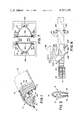
- FIG. 1 illustrates a semiround corrugated tubing structure manufactured in accordance with the method or apparatus of the present invention
- FIG. 4 is further illustrative of the molding blocks for use in conjunction with the molding technique of FIG. 3;
- FIG. 6 is further illustrative of the bonding technique of FIG. 3.
- FIG. 7 is further illustrative of the bonding technique of FIG. 3.
- the present invention is applicable to manufacturing numerous shapes and styles of tubing. It may be used to manufacture semiround tubing including parabolic, semielliptical, semicircular and the like, rectilinear tubing including triangular, rectangular or the like, and many other geometric cross sections of hollow tubing structures which have a flat base area.
- the tubing has a hollow channel extending longitudinally along the tubing to allow fluids and the like to be conveyed through the tubing.
- the hollow is generally formed as a result of a U- or V-shaped cross section of the tubing.
- the tubing may have an integral base to provide a closed circumference or the supporting earth or other structure at the installation site may supply the bottom surface of the channel defined by the tubing structure.
- the tubing structure has an arched, particularly a parabolically arched, cross section.
- FIGS. 1 and 2 are illustrative of a preferred embodiment of the tubing structure which may be manufactured with the present invention.
- the tubing structure is an elongated conduit comprised of a pair of cooperatively spaced side walls 10 and 12. Th side walls are pivotally connected longitudinally at an apex area by a connecting or hinge means 14.
- the hinge means is included so that the tubing structure is longitudinally foldable. A plurality of hinges, such as at the corners of a trapezoid, are also contemplated by the hinge means. If the tubing is not to be folded, then hinge means may be deleted.
- side walls 10 and 12 each have longitudinally extending terminal edge areas 16 and 18 respectively. The terminal edges each have a bearing surface to which a base 20 is attached and upon which the tubing structure and any supported load, such as backfill, rest.
- the side walls 10 and 12 taken together in the unfolded configuration form a parabolic arch, because the parabolic cross section has preferred strength characteristics.
- the side walls may form other semiround or rectilinear structures and the like.
- Semiround it will be appreciated, connotes a generally rounded structure with a generally flat base. It should be construed broadly to include a structure having rounded or curved segments or rectilinear approximations of rounded or curved segments.
- a base 20 When the tubing is installed in a substerranean location, a base 20 generally rests on the floor of a trench or other earthen surface. Thus, the base is supported by the ground. Accordingly, the base 20 need not be constructed with sufficient strength to support the conveyed liquids by itself. Rather the ground and base together support the conveyed liquids. Under distributed vertical loading from back fill, the semiround wall structure tends to flatten. The terminal edge areas 16 and 18 tend to be forced apart by this loading force. Accordingly, base 20 should be a material with a sufficiently high tensil strength that under normal loading conditions it constrains the terminal edges of the side walls from moving apart. A suitable material for base 20 is a ten to fifteen mil polyethylene sheet.
- the polyethylene sheet may be a solid plastic for conveying fluids or may be perforated to allow fluid egress or ingress.
- the sheet-like material may be perforated with 1/8" diameter holes as shown at 26, slotted as shown at 28, or punched with holes of various other sizes and configurations.
- the base may be made of various polymeric materials, mylar, metallic foils, and the like. Alternately, the base may be made of a porous material such as a spun bonded fabric, e.g. Dupont's TYPAR spunbonded polypropylene material, plastic coated fiber glass screening, or other filter or screening materials. The use of porous filter materials is advantageous in drainage situations.
- the filter or screening materials allow the water to enter the hollow of the tubing structure but block sand and other particles which might tend to clog or fill the tubing.
- the sheet-like material which forms the base is foldable to enable the tubing structure to be folded about hinge means 14. As the terminal edge areas 16 and 18 of the tubing are brought together, FIG. 2, a generally flat, folded configuration is formed. As the side walls 10 and 12 are folded together, the base 20 is folded into the interior of the tubing. The relatively rigid side walls protect the relatively flexible base from abrasion, punctures, and the like while in its folded configuration.
- FIG. 3 is illustrative of the apparatus and method of producing generally flat based tubing structures.
- the first step in the manufacturing process is the extrusion of a sleeve of plastic material.
- the extrusion step is performed with an extruder 100 which receives pellets of plastic resin from a resin hopper 102 and subjects the resin to heat and pressure. Under the heat and pressure the plastic is softened and forced through an extrusion die 104 which conforms generally to the shape of the tubing which is to be produced. In the present embodiment, an oval die configuration is preferred. This produces a smooth, oval sleeve 106 of soft plastic material emerging from the extrusion die 104.
- the second step of the manufacturing process is molding the extruded sleeve 106 into the desired configuration.
- Molding is performed with a continuous blow molding means which comprises a plurality of pairs of mold blocks which move in two continuous runs.
- a continuous blow molding means which comprises a plurality of pairs of mold blocks which move in two continuous runs.
- adjacent the extruder 100 a pair 110 and 112 of the many pairs of mold blocks come together and abut.
- the mold blocks then move linearly away from the extruder at substantially the rate sleeve 106 is extruded.
- Interior to the extruded plastic sleeve is a pneumatic means for exerting sufficient pneumatic pressure on the soft plastic to force it to conform with the interior surface of the mold blocks.
- the mold blocks move in contact with the sleeve, sufficient heat is lost from the plastic that the plastic retains the shape of the mold blocks.
- the mold blocks separate allowing a plastic generally tubular structure 114 to emerge.
- the mold blocks circulate continuously forming the soft plastic sleeve into a semirigid, generally tubular structure.
- the generally tubular structure 114 comprises a pair of corrugated, semiround tubing structures, 116 and 118, each shown in FIG. 1 and attached adjacent their terminal edge areas 16 and 18.
- the exact configuration of the tubing structure is, of course, determined by the mold blocks which are chosen to be used.
- the preferred embodiment of the mold blocks is described below in reference to FIG. 4. Alternately more than two tubing structures may be joined to form the generally tubular structure, the tubing structures may be smooth walled, or the tubing structure may have other cross sections than semiround.
- the next step is cooling the plastic generally tubular structure 114 to bring it to a more rigid state.
- a cooling means 120 removes heat from the tubular structure.
- Numerous conventional cooling means may be used, such as a spray of cool water and air.
- cooling fluid may be readily applied to the interior as well as the exterior surfaces.
- the tubing structures may be submerged in a water bath 140 to cool and set the plastic more fully.
- Other cooling means may alternately be employed.
- tubing structures 116 and 118 may optionally be drilled or slotted. Accordingly, a slotting saw or drilling means 150 may cut slots or drill perforations into the side walls of the tubing structures 116 and 118. Slotted or perforated side walls in addition to or instead of the base may be desirable for same applications.
- the next step is bonding the base 20 adjacent the terminal edge areas of the tubing structures 116 and 118.
- a bonding means 160 fastens a strip 162 of sheet-like material across the terminal edges 16 and 18 of the tubing structures 116 and 118.
- the bonding means heat seals a plastic sheet-like material to the bearing surfaces of terminal edges 16 and 18.
- the sheet-like material may be attached by gluing, sewing, solvent welding, or other bonding techniques.
- a pair of folding means 170 and 172 fold the tubing structures 116 and 118.
- Each of the folding means have a receiving end 174 which is dimensioned substantially in conformance with the cross sectional area of the tubing structure in its open configuration (FIG. 1) and a terminal end 176 which is configured substantially in conformance with the tubing in its flat, folded configuration (FIG. 2).
- the folding means 170 tapers gradually from the one configuration to the other. This forces the terminal edges 16 and 18 of two side walls together.
- a projection 178 folds the sheet-like base 20 into the interior of the tubing structure between the side walls in its folded configuration.
- Projection 178 is substantially flat at receiving end 174 and gradually increases to a height of approximately half the width of the base. In this manner as the terminal edges of the side walls are brought together, projection 178 merges base 20 into the interior of the tubing.
- the last step is to coil the folded tubing structures.
- a pair of coiling means 180 and 182 wraps the flattened tubing structure onto spindles or reels.
- coiling means 180 and coiling means 182 rotate in opposite directions. Because the flattened tubing structures 116 and 118, in the preferred embodiment face in opposite directions, coiling the flattened structures in opposite directions causes all coils to look the same.
- the tubing is cut and the new coil is started. Alternately, the tubing may be cut in shorter lengths, such as 10 foot lengths, bundled and stacked.
- FIG. 4 illustrates mold blocks 110 and 112 of FIG. 3 in greater detail. Mold blocks 110 and 112 are mirror images of each other. Accordingly, only mold block 110 will be described in detail and it will be understood that the description applies similarly to mold block 112 and the other mold blocks.
- the mold block 110 has a series of raised and recessed areas around the inside surface 200 to form the valleys and peaks respectively, of the side walls 10 and 12 of the corrugated tubing. Disposed at the center of mold block 110 is a ridge 202 for forming hinge means 14 at the apex area of the tubing structure. Adjacent the abutting edges of mold block 110 is a ledge 204 and a ledge 206 for forming flanges adjacent terminal edge areas 16 and 18, respectively.
- the mold blocks may take various alternative forms.
- the blocks may be configured to form the semiround conduits top and bottom instead of side by side. This may be accomplished by spacing half of ridge 202 adjacent the top of the mold block where ledge 204 is disposed and positioning half of ridge 202 adjacent the bottom of the mold block where ledge 206 is disposed. A recess commensurate in size with ledges 204 and 206 may be disposed where hinge 202 is disposed.
- the interior of the mold blocks need not conform exactly to the configuration of the tubing as shown in FIG. 1. Rather the tubing may be formed with side walls 10 and 12 flexed inward or outward from the unfolded configuration.
- the mold blocks may form a generally tubular structure which is configured to be cut into three or more tubing structures.
- a larger number of mold blocks may be advantageous when larger numbers of tubing structures are molded simultaneously to decrease interference between the mold and tubing structures as the mold blocks are separated.
- splitting the generally tubular structure into a plurality of tubular structures may be performed by many well known methods.
- flanges formed by ledges 204 and 206 of the mold blocks are cut.
- generally tubular structure 114 is formed of two semiround tubing structures 116 and 118.
- Tubing structure 116 is marked with the reference numerals of FIGS. 1 and 2 and tubing structure 118 is marked with the same reference numerals followed by a prime (').
- the terminal edge areas 16 of tubing 116 and 18' of tubing 118 are integrally molded as a rounded flange.
- terminal edge areas 16' and 18 are integrally molded to form a second flange.
- a pair of saw blades 220 and 222 are disposed sufficiently adjacent the generally tubular structure 114 as it is fed through splitting means 130 that the two flanges are severed.
- Saw blades 220 and 222 are disposed to cut substantially parallel to each other and perpendicular to the bases of the tubing structures 116 and 118.
- the saw blades 220 and 222 may be rotating blades, band saws, oscillating blades, or the like. Further, other cutting means such as knife blades, heated blades, or the like may be used.
- a weakened area may be molded into the flanges to facilitate the severing operation.
- the cutting blades may be disposed at other orientations such as parallel to the base of semiround tubing structures 116 and 118.
- Cooling means 140 may be any of a variety of conventionally available structures.
- One such structure would be a trough or vat of water with rollers to guide the tubing below the surface. Blowers may be used to dry the tubing, if desired.
- the optional slotting of perforating operation at 150 may be performed with any of a variety of commercially available slotting saws or drilling tools which are well known in the art.
- the bonding step in the preferred embodiment is performed by extruding a thin bead of plastic material and pressing it between a strip of sheet-like plastic material and the terminal edge areas of the semiround tubing structures.
- the two semiround tubing structures 116 and 118 are continuously fed through the bonding area.
- roll 162 feeds sheet-like material at the same rate as the tubing structures 116 and 118 are advancing.
- Adjacent the roll of plastic material is a slitter blade 230 which splits the plastic material from the roll into two strips 232 and 234 of equal width.
- slitter blade 230 may be replaced with other cutting tools or two rolls of sheet-like material.
- a pair of bars disposed at generally 45 degree angles to the path of travel of the tubing structures acts as means for aligning strips 232 and 234 in parallel with the two tubing structures 116 and 118.
- the sheets 232 and 234 advance between the tubing structures 116 and 118 and parallel thereto.
- a first pair of rollers 240 and 242 press sheet-like material 232 against the bearing surface of the terminal edge 18 of tubing structure 116.
- a second pair of rollers 244 and 246 press sheet 232 against terminal edge 16 of tubing structure 116.
- Rollers 240 and 244 are heated to soften and heat seal the sheet 232 to terminal edges 16 and 18.
- a source 247 of heat softened or melted polyethylene or other plastic material, glue, solvent, or the like may be disposed to deposit a small ribbon or bead of glue or solvent between sheet 232 and terminal edges 16 and 18.
- a sonic welder, sewing device, or other bonding means may also be used.
- a roller 248 coacts with rollers 240, 242, 244, and 246 to constrain the spread of terminal edges 16 and 18 to the desired cross section of tubing structure 116 as sheet 232 is bonded to them. This fixes the unfolded configuration of the tubing structure.
- bonding may be carried out when the side walls are pivoted inward about the hinge means if the sheet 232 is folded by a corresponding amount. It is desireable for the resultant structure to have a uniform cross-sectional area.
- sheet 234 is bonded with tubing structure 118 with a fist pair of rollers 250 and 252 and second pair of rollers 254 and 256 which interact with a roller 258 to adjust the cross section of the semiround tubing structure.
- rollers 240 and 250 may be replaced by a single heating unit against which rollers 242 and 252 press the two terminal edges and the associated sheets.
- rollers 244 and 254 can be replaced by a single heating structure.
Abstract
Description
Claims (32)
Priority Applications (1)
| Application Number | Priority Date | Filing Date | Title |
|---|---|---|---|
| US06/162,006 US4357190A (en) | 1978-12-07 | 1980-06-23 | Method and apparatus for manufacturing non-round plastic tubing |
Applications Claiming Priority (2)
| Application Number | Priority Date | Filing Date | Title |
|---|---|---|---|
| US05/967,514 US4245924A (en) | 1978-12-07 | 1978-12-07 | Arch conduit |
| US06/162,006 US4357190A (en) | 1978-12-07 | 1980-06-23 | Method and apparatus for manufacturing non-round plastic tubing |
Related Parent Applications (1)
| Application Number | Title | Priority Date | Filing Date |
|---|---|---|---|
| US05/967,514 Continuation-In-Part US4245924A (en) | 1978-12-07 | 1978-12-07 | Arch conduit |
Publications (1)
| Publication Number | Publication Date |
|---|---|
| US4357190A true US4357190A (en) | 1982-11-02 |
Family
ID=26858367
Family Applications (1)
| Application Number | Title | Priority Date | Filing Date |
|---|---|---|---|
| US06/162,006 Expired - Lifetime US4357190A (en) | 1978-12-07 | 1980-06-23 | Method and apparatus for manufacturing non-round plastic tubing |
Country Status (1)
| Country | Link |
|---|---|
| US (1) | US4357190A (en) |
Cited By (13)
| Publication number | Priority date | Publication date | Assignee | Title |
|---|---|---|---|---|
| US4527319A (en) * | 1981-09-28 | 1985-07-09 | Hancor, Inc. | Method and apparatus for manufacturing foldable conduit |
| US4875956A (en) * | 1987-10-06 | 1989-10-24 | Integrated Fluidics, Inc. | Method of bonding plastics |
| US4999069A (en) * | 1987-10-06 | 1991-03-12 | Integrated Fluidics, Inc. | Method of bonding plastics |
| US5041181A (en) * | 1987-10-06 | 1991-08-20 | Integrated Fluidics Company | Method of bonding plastics |
| EP0642915A1 (en) * | 1993-09-10 | 1995-03-15 | Hydromatic Ltd. | Method and apparatus for making drip irrigation lines and preformed member for use therein |
| EP0670019A1 (en) * | 1992-11-17 | 1995-09-06 | Proprietary Technology, Inc. | Self locking slitted corrugated tubing |
| WO2000058560A1 (en) * | 1999-03-31 | 2000-10-05 | Societe Etex De Recherches Techniques, S.E.R.T. | Conduit element, method for making same and assembly component |
| FR2791713A1 (en) * | 1999-03-31 | 2000-10-06 | Nicoll Raccords Plastiques | Thermoplastic duct component has twin extruded walls - smooth inner wall and outer corrugated one |
| US20080107765A1 (en) * | 2006-10-20 | 2008-05-08 | Considine Ana R | Apparatus, system, and method for manufacturing irregularly shaped panel filters |
| EP2106897A1 (en) * | 2008-04-04 | 2009-10-07 | Wavin B.V. | Plastic pipe with profiled layer and method for manufacturing the same |
| EP2428716A1 (en) * | 2010-09-14 | 2012-03-14 | Hutchinson, Srl | Fluid transfer pipe with corrugated portion(s) and method for manufacturing same |
| CN111438716A (en) * | 2020-04-10 | 2020-07-24 | 周瑞敏 | Special cutting machine for PE pipe production and use method thereof |
| US11795679B2 (en) | 2021-07-19 | 2023-10-24 | Prinsco, Inc. | Asymmetric leaching chamber for onsite wastewater management system |
Citations (35)
| Publication number | Priority date | Publication date | Assignee | Title |
|---|---|---|---|---|
| US1606270A (en) * | 1920-02-28 | 1926-11-09 | Herbert R Stratford | Apparatus for and method of making rubber tubes |
| US2614953A (en) * | 1946-02-09 | 1952-10-21 | American Viscose Corp | Heat-sealing element |
| US2632724A (en) * | 1948-01-10 | 1953-03-24 | L A Goodman Mfg Company | Method for bonding hollow plastic bodies |
| US2702410A (en) * | 1951-06-21 | 1955-02-22 | Western Electric Co | Method of working and extruding plastic compounds |
| US3248463A (en) * | 1962-02-15 | 1966-04-26 | Phillips Petroleum Co | Continuous production of biaxially oriented crystalline thermoplastic film |
| US3280430A (en) * | 1965-05-24 | 1966-10-25 | Acme Hamilton Mfg Corp | Apparatus for making corrugated plastic tubing |
| US3349156A (en) * | 1959-02-21 | 1967-10-24 | Fraenk Isolierrohr & Metall | Method for the production of corrugated tubes |
| US3479419A (en) * | 1965-05-03 | 1969-11-18 | Irving Hochhauser | Process and apparatus for curing material by induction heating |
| US3558410A (en) * | 1965-06-28 | 1971-01-26 | Nat Distillers Chem Corp | Extrusion method and apparatus for the extrusion of rectangular tubes of thermoplastic sheet |
| US3579402A (en) * | 1968-04-23 | 1971-05-18 | Goldsworthy Eng Inc | Method and apparatus for producing filament reinforced tubular products on a continuous basis |
| US3650868A (en) * | 1968-03-27 | 1972-03-21 | Furukawa Electric Co Ltd | Methods and apparatus for manufacturing pipe-shaped articles from foamed thermoplastic resin |
| US3705779A (en) * | 1969-12-22 | 1972-12-12 | Wavin Bv | Device for manufacturing a plastic tube with transverse grooves |
| US3799418A (en) * | 1972-06-13 | 1974-03-26 | Plastic Tubing | Apparatus and method for positively feeding corrugated pipe |
| US3809593A (en) * | 1968-06-24 | 1974-05-07 | Union Camp Corp | Method and apparatus for the continuous manufacture of collapsible cellular partitions |
| US3843758A (en) * | 1972-07-13 | 1974-10-22 | Plastic Tubing | Method for making and slitting plastic corrugated tubes |
| US3854527A (en) * | 1972-09-01 | 1974-12-17 | E Maroschak | Apparatus and method for fabricating corrugated plastic tubing |
| US3864446A (en) * | 1972-06-12 | 1975-02-04 | Plastic Tubing | Method of converting corrugated pipe molding machine |
| US3870774A (en) * | 1972-08-04 | 1975-03-11 | Ernest J Maroschak | Pipe doffing and bundling method |
| US3871807A (en) * | 1972-01-12 | 1975-03-18 | Pont A Mousson | Device for forming tubes of thermoplastic material by extrusion |
| US3877831A (en) * | 1972-06-13 | 1975-04-15 | Ernest J Maroschak | Method of apparatus for drilling holes in tubes |
| US3892514A (en) * | 1972-06-13 | 1975-07-01 | Nordstroem Erik G W | Apparatus for producing corrugated plastic pipe with holes in the pipe wall |
| US3893465A (en) * | 1974-04-22 | 1975-07-08 | Jess & Lowell Well Casing Co | Guide device for plastic tube extrusion |
| US3910713A (en) * | 1972-06-13 | 1975-10-07 | Ernest J Maroschak | Method for making corrugated plastic tubing |
| US3916763A (en) * | 1972-07-13 | 1975-11-04 | Ernest J Maroschak | Apparatus for forming slits in tubes |
| US3990827A (en) * | 1972-07-13 | 1976-11-09 | Plastic Tubing, Inc. | Apparatus for making corrugated plastic pipe with integral coupler collars |
| US4003122A (en) * | 1975-12-29 | 1977-01-18 | Francesville Drain Tile Corporation | Apparatus and method for applying filter to a drainage tubing |
| US4003685A (en) * | 1974-10-09 | 1977-01-18 | Maroschak Ernest J | Apparatus for molding plastic pipe with enlarged portions formed therein |
| JPS5210363A (en) * | 1975-07-15 | 1977-01-26 | Matsushita Electric Works Ltd | Method of producing gutter |
| US4112810A (en) * | 1976-10-20 | 1978-09-12 | Advanced Drainage Systems, Inc. | Tube slotter |
| US4115495A (en) * | 1977-04-06 | 1978-09-19 | The B. F. Goodrich Company | Processing extruded thermoplastic polymer |
| US4124426A (en) * | 1975-03-25 | 1978-11-07 | Saul Franz J | Method and apparatus for producing a collapsibly foldable packaging sleeve having a polygonal cross-section |
| US4192699A (en) * | 1977-03-16 | 1980-03-11 | Lewicki Gregory D | Method of making inflatable cellular assemblies of plastic material |
| US4194081A (en) * | 1977-10-11 | 1980-03-18 | Dayco Corporation | Vaccum cleaner hose construction having electrical conductors extending therealong and method of making same |
| US4222807A (en) * | 1978-10-16 | 1980-09-16 | Joseph Farber | Ridged surface solar heater |
| US4245924A (en) * | 1978-12-07 | 1981-01-20 | Hancor, Inc. | Arch conduit |
-
1980
- 1980-06-23 US US06/162,006 patent/US4357190A/en not_active Expired - Lifetime
Patent Citations (35)
| Publication number | Priority date | Publication date | Assignee | Title |
|---|---|---|---|---|
| US1606270A (en) * | 1920-02-28 | 1926-11-09 | Herbert R Stratford | Apparatus for and method of making rubber tubes |
| US2614953A (en) * | 1946-02-09 | 1952-10-21 | American Viscose Corp | Heat-sealing element |
| US2632724A (en) * | 1948-01-10 | 1953-03-24 | L A Goodman Mfg Company | Method for bonding hollow plastic bodies |
| US2702410A (en) * | 1951-06-21 | 1955-02-22 | Western Electric Co | Method of working and extruding plastic compounds |
| US3349156A (en) * | 1959-02-21 | 1967-10-24 | Fraenk Isolierrohr & Metall | Method for the production of corrugated tubes |
| US3248463A (en) * | 1962-02-15 | 1966-04-26 | Phillips Petroleum Co | Continuous production of biaxially oriented crystalline thermoplastic film |
| US3479419A (en) * | 1965-05-03 | 1969-11-18 | Irving Hochhauser | Process and apparatus for curing material by induction heating |
| US3280430A (en) * | 1965-05-24 | 1966-10-25 | Acme Hamilton Mfg Corp | Apparatus for making corrugated plastic tubing |
| US3558410A (en) * | 1965-06-28 | 1971-01-26 | Nat Distillers Chem Corp | Extrusion method and apparatus for the extrusion of rectangular tubes of thermoplastic sheet |
| US3650868A (en) * | 1968-03-27 | 1972-03-21 | Furukawa Electric Co Ltd | Methods and apparatus for manufacturing pipe-shaped articles from foamed thermoplastic resin |
| US3579402A (en) * | 1968-04-23 | 1971-05-18 | Goldsworthy Eng Inc | Method and apparatus for producing filament reinforced tubular products on a continuous basis |
| US3809593A (en) * | 1968-06-24 | 1974-05-07 | Union Camp Corp | Method and apparatus for the continuous manufacture of collapsible cellular partitions |
| US3705779A (en) * | 1969-12-22 | 1972-12-12 | Wavin Bv | Device for manufacturing a plastic tube with transverse grooves |
| US3871807A (en) * | 1972-01-12 | 1975-03-18 | Pont A Mousson | Device for forming tubes of thermoplastic material by extrusion |
| US3864446A (en) * | 1972-06-12 | 1975-02-04 | Plastic Tubing | Method of converting corrugated pipe molding machine |
| US3799418A (en) * | 1972-06-13 | 1974-03-26 | Plastic Tubing | Apparatus and method for positively feeding corrugated pipe |
| US3877831A (en) * | 1972-06-13 | 1975-04-15 | Ernest J Maroschak | Method of apparatus for drilling holes in tubes |
| US3892514A (en) * | 1972-06-13 | 1975-07-01 | Nordstroem Erik G W | Apparatus for producing corrugated plastic pipe with holes in the pipe wall |
| US3910713A (en) * | 1972-06-13 | 1975-10-07 | Ernest J Maroschak | Method for making corrugated plastic tubing |
| US3843758A (en) * | 1972-07-13 | 1974-10-22 | Plastic Tubing | Method for making and slitting plastic corrugated tubes |
| US3916763A (en) * | 1972-07-13 | 1975-11-04 | Ernest J Maroschak | Apparatus for forming slits in tubes |
| US3990827A (en) * | 1972-07-13 | 1976-11-09 | Plastic Tubing, Inc. | Apparatus for making corrugated plastic pipe with integral coupler collars |
| US3870774A (en) * | 1972-08-04 | 1975-03-11 | Ernest J Maroschak | Pipe doffing and bundling method |
| US3854527A (en) * | 1972-09-01 | 1974-12-17 | E Maroschak | Apparatus and method for fabricating corrugated plastic tubing |
| US3893465A (en) * | 1974-04-22 | 1975-07-08 | Jess & Lowell Well Casing Co | Guide device for plastic tube extrusion |
| US4003685A (en) * | 1974-10-09 | 1977-01-18 | Maroschak Ernest J | Apparatus for molding plastic pipe with enlarged portions formed therein |
| US4124426A (en) * | 1975-03-25 | 1978-11-07 | Saul Franz J | Method and apparatus for producing a collapsibly foldable packaging sleeve having a polygonal cross-section |
| JPS5210363A (en) * | 1975-07-15 | 1977-01-26 | Matsushita Electric Works Ltd | Method of producing gutter |
| US4003122A (en) * | 1975-12-29 | 1977-01-18 | Francesville Drain Tile Corporation | Apparatus and method for applying filter to a drainage tubing |
| US4112810A (en) * | 1976-10-20 | 1978-09-12 | Advanced Drainage Systems, Inc. | Tube slotter |
| US4192699A (en) * | 1977-03-16 | 1980-03-11 | Lewicki Gregory D | Method of making inflatable cellular assemblies of plastic material |
| US4115495A (en) * | 1977-04-06 | 1978-09-19 | The B. F. Goodrich Company | Processing extruded thermoplastic polymer |
| US4194081A (en) * | 1977-10-11 | 1980-03-18 | Dayco Corporation | Vaccum cleaner hose construction having electrical conductors extending therealong and method of making same |
| US4222807A (en) * | 1978-10-16 | 1980-09-16 | Joseph Farber | Ridged surface solar heater |
| US4245924A (en) * | 1978-12-07 | 1981-01-20 | Hancor, Inc. | Arch conduit |
Cited By (18)
| Publication number | Priority date | Publication date | Assignee | Title |
|---|---|---|---|---|
| US4527319A (en) * | 1981-09-28 | 1985-07-09 | Hancor, Inc. | Method and apparatus for manufacturing foldable conduit |
| US4875956A (en) * | 1987-10-06 | 1989-10-24 | Integrated Fluidics, Inc. | Method of bonding plastics |
| US4999069A (en) * | 1987-10-06 | 1991-03-12 | Integrated Fluidics, Inc. | Method of bonding plastics |
| US5041181A (en) * | 1987-10-06 | 1991-08-20 | Integrated Fluidics Company | Method of bonding plastics |
| EP0670019A1 (en) * | 1992-11-17 | 1995-09-06 | Proprietary Technology, Inc. | Self locking slitted corrugated tubing |
| EP0670019A4 (en) * | 1992-11-17 | 1996-12-18 | Proprietary Technology Inc | Self locking slitted corrugated tubing. |
| EP0642915A1 (en) * | 1993-09-10 | 1995-03-15 | Hydromatic Ltd. | Method and apparatus for making drip irrigation lines and preformed member for use therein |
| FR2791713A1 (en) * | 1999-03-31 | 2000-10-06 | Nicoll Raccords Plastiques | Thermoplastic duct component has twin extruded walls - smooth inner wall and outer corrugated one |
| WO2000058560A1 (en) * | 1999-03-31 | 2000-10-05 | Societe Etex De Recherches Techniques, S.E.R.T. | Conduit element, method for making same and assembly component |
| US20080107765A1 (en) * | 2006-10-20 | 2008-05-08 | Considine Ana R | Apparatus, system, and method for manufacturing irregularly shaped panel filters |
| US8272418B2 (en) * | 2006-10-20 | 2012-09-25 | Cummins Filtration Ip, Inc. | Apparatus, system, and method for manufacturing irregularly shaped panel filters |
| EP2106897A1 (en) * | 2008-04-04 | 2009-10-07 | Wavin B.V. | Plastic pipe with profiled layer and method for manufacturing the same |
| WO2009121972A1 (en) * | 2008-04-04 | 2009-10-08 | Wavin B.V. | Plastic pipe with profiled layer and method for manufacturing the same |
| EP2428716A1 (en) * | 2010-09-14 | 2012-03-14 | Hutchinson, Srl | Fluid transfer pipe with corrugated portion(s) and method for manufacturing same |
| ITMI20101671A1 (en) * | 2010-09-14 | 2012-03-15 | Hutchinson Srl | TUBE FOR THE TRANSFER OF A FLUID WITH PORTION (I) CORRUGATED (E) AND ITS MANUFACTURING PROCEDURE |
| US8991438B2 (en) | 2010-09-14 | 2015-03-31 | Hutchinson Srl | Fluid transfer pipe with corrugated portion(s) and method for manufacturing same |
| CN111438716A (en) * | 2020-04-10 | 2020-07-24 | 周瑞敏 | Special cutting machine for PE pipe production and use method thereof |
| US11795679B2 (en) | 2021-07-19 | 2023-10-24 | Prinsco, Inc. | Asymmetric leaching chamber for onsite wastewater management system |
Similar Documents
| Publication | Publication Date | Title |
|---|---|---|
| US4357190A (en) | Method and apparatus for manufacturing non-round plastic tubing | |
| US4406326A (en) | Plastic well screen and method of forming same | |
| EP1030776B1 (en) | Spiral formed products and method of manufacture | |
| EP1301970B1 (en) | Optic cable conduit insert and method of manufacture | |
| JP3170270B2 (en) | Foam article and method for producing the same | |
| JP4219428B2 (en) | Method for manufacturing a thermally insulated conduit | |
| US5591293A (en) | Process for manufacturing drip irrigation systems using plastic lamination/extrusion techniques | |
| US10246224B2 (en) | Plastic bags, rolls of plastic bags, and tubular blown film processes of making the same | |
| EP0247073A1 (en) | Plastic bag and method and apparatus of manufacture. | |
| US20040187946A1 (en) | Manufacturing process and apparatus for making a helical rib tube | |
| US4164170A (en) | Method of making bags | |
| MX2009000401A (en) | A method and apparatus for manufacturing a transversely oriented film of thermoplastic polymer material and products obtainable by the same method. | |
| NL7904861A (en) | HEAT-INSULATED PIPE TUBE. | |
| US4374079A (en) | Method and apparatus for manufacturing expanded and layered semiround plastic tubings | |
| JPS6043301B2 (en) | Multilayer laminated film and its manufacturing method | |
| KR102166700B1 (en) | Air-cooled manufacturing method for drainage material for soft ground improvement | |
| US5862591A (en) | Method for manufacturing paint rollers | |
| US5741208A (en) | Environmental container liner and method of manufacture | |
| IT1284066B1 (en) | PROCEDURE AND SYSTEM FOR THE PRODUCTION OF RECYCLED THERMOPLASTIC RESIN TUBES | |
| US4029539A (en) | Apparatus for forming a stretchable tubular packaging material | |
| GB2354971A (en) | A bag featuring longitudinally reinforcing folds | |
| EP0114741B1 (en) | Production of foams | |
| KR102207930B1 (en) | Air-cooled manufacturing device for drainage material for soft ground improvement | |
| US3018882A (en) | Spiral roll of perforated thermoplastic multiple tubing and method and apparatus for producing same | |
| US5217557A (en) | Process for the production of thermoplastic levee gates |
Legal Events
| Date | Code | Title | Description |
|---|---|---|---|
| AS | Assignment |
Owner name: HANCOR, INC. Free format text: ASSIGNMENT OF ASSIGNORS INTEREST.;ASSIGNOR:CHILD, JAMES L., JR.;REEL/FRAME:003914/0377 Effective date: 19810921 |
|
| AS | Assignment |
Owner name: NATIONAL CITY BANK, (THE AGENT) Free format text: ASSIGNMENT OF ASSIGNORS INTEREST.;ASSIGNOR:HANCOR, INC., AN OH CORP.;REEL/FRAME:004076/0605 Effective date: 19821208 Owner name: NATIONAL CITY BANK, (THE AGENT), OHIO Free format text: ASSIGNMENT OF ASSIGNORS INTEREST;ASSIGNOR:HANCOR, INC., AN OH CORP.;REEL/FRAME:004076/0605 Effective date: 19821208 |
|
| STCF | Information on status: patent grant |
Free format text: PATENTED CASE |
|
| CC | Certificate of correction | ||
| AS | Assignment |
Owner name: HANCOR, INC. Free format text: RELEASED BY SECURED PARTY;ASSIGNOR:NATIONAL CITY BANK, AS AGENT;REEL/FRAME:004684/0172 Effective date: 19860422 Owner name: NAIONAL CITY BANK Free format text: SECURITY INTEREST;ASSIGNOR:HANCOR, INC. A CORP. OF OH.;REEL/FRAME:004684/0176 Effective date: 19860422 |
|
| AS | Assignment |
Owner name: NATIONAL CITY BANK Free format text: SECURITY INTEREST;ASSIGNOR:HANCOR, INC., A CORP. OF OH;REEL/FRAME:005404/0116 Effective date: 19900713 |
|
| AS | Assignment |
Owner name: NATIONAL CITY BANK, OHIO Free format text: SECOND AMENDED AND RESTATED COLLATERAL ASSIGNMENT OF PATENTS;ASSIGNOR:HANCOR, INC.;REEL/FRAME:006331/0651 Effective date: 19920923 |