US4354351A - Load sensing steering - Google Patents
Load sensing steering Download PDFInfo
- Publication number
- US4354351A US4354351A US06/250,754 US25075480A US4354351A US 4354351 A US4354351 A US 4354351A US 25075480 A US25075480 A US 25075480A US 4354351 A US4354351 A US 4354351A
- Authority
- US
- United States
- Prior art keywords
- fluid
- flowing
- valve
- directing
- steering
- Prior art date
- Legal status (The legal status is an assumption and is not a legal conclusion. Google has not performed a legal analysis and makes no representation as to the accuracy of the status listed.)
- Expired - Lifetime
Links
- 239000012530 fluid Substances 0.000 claims abstract description 83
- 230000004044 response Effects 0.000 claims abstract description 13
- 230000000903 blocking effect Effects 0.000 claims description 10
- 238000001816 cooling Methods 0.000 claims description 6
- 230000006872 improvement Effects 0.000 claims description 3
- 238000013022 venting Methods 0.000 claims 2
- 230000006903 response to temperature Effects 0.000 claims 1
- 230000008901 benefit Effects 0.000 description 3
- 239000010720 hydraulic oil Substances 0.000 description 2
- 239000003921 oil Substances 0.000 description 2
- 239000000654 additive Substances 0.000 description 1
- 230000001419 dependent effect Effects 0.000 description 1
- 230000007246 mechanism Effects 0.000 description 1
- 230000037361 pathway Effects 0.000 description 1
Images


Classifications
-
- B—PERFORMING OPERATIONS; TRANSPORTING
- B62—LAND VEHICLES FOR TRAVELLING OTHERWISE THAN ON RAILS
- B62D—MOTOR VEHICLES; TRAILERS
- B62D5/00—Power-assisted or power-driven steering
- B62D5/06—Power-assisted or power-driven steering fluid, i.e. using a pressurised fluid for most or all the force required for steering a vehicle
-
- F—MECHANICAL ENGINEERING; LIGHTING; HEATING; WEAPONS; BLASTING
- F15—FLUID-PRESSURE ACTUATORS; HYDRAULICS OR PNEUMATICS IN GENERAL
- F15B—SYSTEMS ACTING BY MEANS OF FLUIDS IN GENERAL; FLUID-PRESSURE ACTUATORS, e.g. SERVOMOTORS; DETAILS OF FLUID-PRESSURE SYSTEMS, NOT OTHERWISE PROVIDED FOR
- F15B21/00—Common features of fluid actuator systems; Fluid-pressure actuator systems or details thereof, not covered by any other group of this subclass
- F15B21/04—Special measures taken in connection with the properties of the fluid
- F15B21/042—Controlling the temperature of the fluid
- F15B21/0423—Cooling
-
- F—MECHANICAL ENGINEERING; LIGHTING; HEATING; WEAPONS; BLASTING
- F15—FLUID-PRESSURE ACTUATORS; HYDRAULICS OR PNEUMATICS IN GENERAL
- F15B—SYSTEMS ACTING BY MEANS OF FLUIDS IN GENERAL; FLUID-PRESSURE ACTUATORS, e.g. SERVOMOTORS; DETAILS OF FLUID-PRESSURE SYSTEMS, NOT OTHERWISE PROVIDED FOR
- F15B21/00—Common features of fluid actuator systems; Fluid-pressure actuator systems or details thereof, not covered by any other group of this subclass
- F15B21/04—Special measures taken in connection with the properties of the fluid
- F15B21/042—Controlling the temperature of the fluid
- F15B21/0427—Heating
-
- F—MECHANICAL ENGINEERING; LIGHTING; HEATING; WEAPONS; BLASTING
- F15—FLUID-PRESSURE ACTUATORS; HYDRAULICS OR PNEUMATICS IN GENERAL
- F15B—SYSTEMS ACTING BY MEANS OF FLUIDS IN GENERAL; FLUID-PRESSURE ACTUATORS, e.g. SERVOMOTORS; DETAILS OF FLUID-PRESSURE SYSTEMS, NOT OTHERWISE PROVIDED FOR
- F15B2211/00—Circuits for servomotor systems
- F15B2211/20—Fluid pressure source, e.g. accumulator or variable axial piston pump
- F15B2211/205—Systems with pumps
- F15B2211/2053—Type of pump
- F15B2211/20546—Type of pump variable capacity
-
- F—MECHANICAL ENGINEERING; LIGHTING; HEATING; WEAPONS; BLASTING
- F15—FLUID-PRESSURE ACTUATORS; HYDRAULICS OR PNEUMATICS IN GENERAL
- F15B—SYSTEMS ACTING BY MEANS OF FLUIDS IN GENERAL; FLUID-PRESSURE ACTUATORS, e.g. SERVOMOTORS; DETAILS OF FLUID-PRESSURE SYSTEMS, NOT OTHERWISE PROVIDED FOR
- F15B2211/00—Circuits for servomotor systems
- F15B2211/20—Fluid pressure source, e.g. accumulator or variable axial piston pump
- F15B2211/205—Systems with pumps
- F15B2211/20576—Systems with pumps with multiple pumps
-
- F—MECHANICAL ENGINEERING; LIGHTING; HEATING; WEAPONS; BLASTING
- F15—FLUID-PRESSURE ACTUATORS; HYDRAULICS OR PNEUMATICS IN GENERAL
- F15B—SYSTEMS ACTING BY MEANS OF FLUIDS IN GENERAL; FLUID-PRESSURE ACTUATORS, e.g. SERVOMOTORS; DETAILS OF FLUID-PRESSURE SYSTEMS, NOT OTHERWISE PROVIDED FOR
- F15B2211/00—Circuits for servomotor systems
- F15B2211/40—Flow control
- F15B2211/415—Flow control characterised by the connections of the flow control means in the circuit
- F15B2211/41572—Flow control characterised by the connections of the flow control means in the circuit being connected to a pressure source and an output member
-
- F—MECHANICAL ENGINEERING; LIGHTING; HEATING; WEAPONS; BLASTING
- F15—FLUID-PRESSURE ACTUATORS; HYDRAULICS OR PNEUMATICS IN GENERAL
- F15B—SYSTEMS ACTING BY MEANS OF FLUIDS IN GENERAL; FLUID-PRESSURE ACTUATORS, e.g. SERVOMOTORS; DETAILS OF FLUID-PRESSURE SYSTEMS, NOT OTHERWISE PROVIDED FOR
- F15B2211/00—Circuits for servomotor systems
- F15B2211/40—Flow control
- F15B2211/42—Flow control characterised by the type of actuation
- F15B2211/426—Flow control characterised by the type of actuation electrically or electronically
-
- F—MECHANICAL ENGINEERING; LIGHTING; HEATING; WEAPONS; BLASTING
- F15—FLUID-PRESSURE ACTUATORS; HYDRAULICS OR PNEUMATICS IN GENERAL
- F15B—SYSTEMS ACTING BY MEANS OF FLUIDS IN GENERAL; FLUID-PRESSURE ACTUATORS, e.g. SERVOMOTORS; DETAILS OF FLUID-PRESSURE SYSTEMS, NOT OTHERWISE PROVIDED FOR
- F15B2211/00—Circuits for servomotor systems
- F15B2211/40—Flow control
- F15B2211/42—Flow control characterised by the type of actuation
- F15B2211/428—Flow control characterised by the type of actuation actuated by fluid pressure
-
- F—MECHANICAL ENGINEERING; LIGHTING; HEATING; WEAPONS; BLASTING
- F15—FLUID-PRESSURE ACTUATORS; HYDRAULICS OR PNEUMATICS IN GENERAL
- F15B—SYSTEMS ACTING BY MEANS OF FLUIDS IN GENERAL; FLUID-PRESSURE ACTUATORS, e.g. SERVOMOTORS; DETAILS OF FLUID-PRESSURE SYSTEMS, NOT OTHERWISE PROVIDED FOR
- F15B2211/00—Circuits for servomotor systems
- F15B2211/60—Circuit components or control therefor
- F15B2211/61—Secondary circuits
- F15B2211/611—Diverting circuits, e.g. for cooling or filtering
-
- F—MECHANICAL ENGINEERING; LIGHTING; HEATING; WEAPONS; BLASTING
- F15—FLUID-PRESSURE ACTUATORS; HYDRAULICS OR PNEUMATICS IN GENERAL
- F15B—SYSTEMS ACTING BY MEANS OF FLUIDS IN GENERAL; FLUID-PRESSURE ACTUATORS, e.g. SERVOMOTORS; DETAILS OF FLUID-PRESSURE SYSTEMS, NOT OTHERWISE PROVIDED FOR
- F15B2211/00—Circuits for servomotor systems
- F15B2211/60—Circuit components or control therefor
- F15B2211/62—Cooling or heating means
-
- F—MECHANICAL ENGINEERING; LIGHTING; HEATING; WEAPONS; BLASTING
- F15—FLUID-PRESSURE ACTUATORS; HYDRAULICS OR PNEUMATICS IN GENERAL
- F15B—SYSTEMS ACTING BY MEANS OF FLUIDS IN GENERAL; FLUID-PRESSURE ACTUATORS, e.g. SERVOMOTORS; DETAILS OF FLUID-PRESSURE SYSTEMS, NOT OTHERWISE PROVIDED FOR
- F15B2211/00—Circuits for servomotor systems
- F15B2211/60—Circuit components or control therefor
- F15B2211/63—Electronic controllers
- F15B2211/6303—Electronic controllers using input signals
- F15B2211/6343—Electronic controllers using input signals representing a temperature
-
- F—MECHANICAL ENGINEERING; LIGHTING; HEATING; WEAPONS; BLASTING
- F15—FLUID-PRESSURE ACTUATORS; HYDRAULICS OR PNEUMATICS IN GENERAL
- F15B—SYSTEMS ACTING BY MEANS OF FLUIDS IN GENERAL; FLUID-PRESSURE ACTUATORS, e.g. SERVOMOTORS; DETAILS OF FLUID-PRESSURE SYSTEMS, NOT OTHERWISE PROVIDED FOR
- F15B2211/00—Circuits for servomotor systems
- F15B2211/70—Output members, e.g. hydraulic motors or cylinders or control therefor
- F15B2211/705—Output members, e.g. hydraulic motors or cylinders or control therefor characterised by the type of output members or actuators
- F15B2211/7051—Linear output members
- F15B2211/7053—Double-acting output members
- F15B2211/7054—Having equal piston areas
-
- F—MECHANICAL ENGINEERING; LIGHTING; HEATING; WEAPONS; BLASTING
- F15—FLUID-PRESSURE ACTUATORS; HYDRAULICS OR PNEUMATICS IN GENERAL
- F15B—SYSTEMS ACTING BY MEANS OF FLUIDS IN GENERAL; FLUID-PRESSURE ACTUATORS, e.g. SERVOMOTORS; DETAILS OF FLUID-PRESSURE SYSTEMS, NOT OTHERWISE PROVIDED FOR
- F15B2211/00—Circuits for servomotor systems
- F15B2211/80—Other types of control related to particular problems or conditions
- F15B2211/85—Control during special operating conditions
- F15B2211/851—Control during special operating conditions during starting
Definitions
- This invention relates generally to a fluid circuit and more particularly to a steering circuit having continuous flow therethrough to keep the oil in the lines warm in cold weather conditions.
- the hydraulic fluid in a steering circuit or in other circuits may increase in viscosity to a magnitude sufficient to make the system slow to respond.
- One particular location at which the hydraulic fluid can easily become excessively viscous is in the relatively long conduits which provide the fluid pathway between the steering control valve and the hydraulic cylinder which actuates the steering mechanism.
- the fluid in these long conduits can cool to a value at which the pump pressure is slow to move the viscous fluid in the conduit upon actuation of the steering valve.
- actuation is responsive to physical movement of the clutch or brake pedal which serves to mechanically push a control valve into a position to deactivate the trickle flow through the long lines when the brake or clutch is activated, and to reactivate the trickle flow when the brake or clutch is deactivated.
- Such mechanical parts can conceivably hang up, due to friction, wear, or the like, in incorrect positions, thus causing undesirable deactuation of the trickle flow when such is desirable.
- the present invention is directed to overcoming one or more of the problems as set forth above.
- an improvement in a fluid circuit having a pressurized fluid source, a fluid actuator and a directional control valve selectively positionable in first (closed) and second (open) positions and being connected to receive pressurized fluid from the source.
- the circuit includes circulating means for circulating fluid from the valve to the actuator in response to positioning of the valve in the second position and flowing means for flowing pressurized fluid into and from the circulating means.
- the improvement comprises logic means for preventing operation of the flowing means in response to positioning of the valve in the second position and to the pressure of the fluid in the circulating means exceeding a selected level.
- An improved circuit as set out above has the advantage that it is automatically actuated in response to load sensed by the circuit and is not dependent upon positioning of a lever or other mechanical member, but only positioning of the control valve.
- Flow is provided through the long hydraulic lines which connect the control valve with a fluid actuator ensuring that the fluid passing through such lines is kept warm in cold weather conditions.
- flow through the lines connecting the control valve to the actuator can be terminated when the fluid temperature is sufficiently high.
- means can be provided for cooling the fluid which is flowing through the hydraulic lines which connect the control valve to the fluid actuator during warm weather, thus allowing a relatively viscous oil, such as SAE-10 hydraulic oil, to be utilized on an all year round basis without the need to dilute with additives.
- FIG. 1 illustrates, schematically, one embodiment of the present invention
- FIG. 2 illustrates, schematically, a portion of the embodiment of FIG. 1 in an alternate mode of actuation
- FIG. 3 illustrates, schematically, a second embodiment of the present invention
- FIG. 4 illustrates, schematically, the embodiment of FIG. 3 in an alternate mode of actuation
- FIG. 5 illustrates, schematically, a third embodiment of the present invention.
- FIG. 6 illustrates, schematically, a portion of the embodiment of FIG. 5 in an alternate mode of actuation.
- FIG. 1 shows a fluid circuit 10 having a pressurized fluid source of pump 12 which supplies fluid to a fluid actuator 14 which may be a double acting hydraulic cylinder of a vehicle steering system.
- a directional control valve 16 is connected to receive pressurized fluid from the pump 12 as via a conduit 18.
- the valve 16 might typically be a directional control steering valve.
- Circulating means 20, in the embodiment illustrated, a pair of conduits 22 and 24, serves for circulating fluid from the valve 16 to the actuator 14 in response to the positioning of the valve 16 in a selected one of first and second positions thereof.
- FIG. 1 shows the valve in its first or blocked position.
- FIG. 2 shows the valve in its second position wherein fluid flows inwardly via conduit 24 and outwardly via conduit 22 to a sump 25.
- the particular valve 16 illustrated also has a third position, shifted upwardly from the position shown in FIG. 1, wherein flow is inwardly via conduit 22 and outwardly via conduit 24 and wherein the fluid actuator 14 is motivated in an opposite direction from that in which it is actuated with the valve 16 positioned as shown in FIG. 2.
- Flowing means 26, seen in FIG. 1 serves for flowing pressurized fluid into the circulating means 20 and for flowing that pressurized fluid away from the circulating means 20.
- the particular flowing means 26 shown includes first flowing means 28 for delivering fluid to the circulating means 20 and second flowing means 30 for removing fluid from the circulating means 20.
- a cooler bypass pump 32 or equivalent means serves for supplying pressurized fluid to the first flowing means 28.
- logic means 34 serves for preventing operation of the flowing means 26 in response to positioning of the control valve 16 in its second position (as shown in FIG. 1) and to the pressure of the fluid in the circulating means 20 exceeding a selected level.
- the preferred logic means 34 includes a blocking valve 36 having an open position (as shown in FIG. 1) and a blocked position (as shown in FIG. 2).
- the logic means 20 also includes biasing means 38, in the embodiment illustrated a spring, which serves for normally biasing the blocking valve 36 into its open position.
- the logic means 20 includes means 40, in the embodiment illustrated a conduit 42, for delivering a signal, determined by the pressure of the fluid in the circulating means 20, in opposition to the biasing means 38, in response to positioning of the control valve 16 in its second position.
- the pressure in the circulating means 20 exceeds a selected value, the pressure in the conduit 42 is sufficient to propel the blocking valve 36 to its blocked position as shown in FIG. 2.
- cooling means 44 may be provided for cooling the fluid in the flowing means 26.
- the cooling means 44 is particularly useful when the apparatus is used during warm weather since it will allow relatively viscous hydraulic fluid, for example, SAE-10 hydraulic oil, to be utilized in warm weather. This allows the same fluid to be utilized in both warm weather and cool weather.
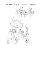
- FIGS. 3 and 4 illustrates an embodiment of the present invention wherein certain of the hydraulically actuated elements of the embodiment of FIGS. 1 and 2 have been replaced by electrically actuated components.
- FIG. 3 replaces the blocking valve 36 of FIGS. 1 and 2 with a first solenoid actuated valve 36a and a second solenoid actuated valve 36b.
- These two solenoid actuated valves together comprise blocking valve means 34' of the embodiment of FIGS. 3 and 4.
- FIG. 3 shows the valves 36a and 36b in their first or open position and FIG. 4 shows these valves in their second or blocked positions.
- a pressure switch 46 is positioned to close a circuit from a battery 48 through the solenoids which actuate each of the valves 36a and 36b to ground. Flow then proceeds from the pump 12 (rather than from a cooler bypass pump 32 as in FIGS. 1 and 2) via a conduit 50, through first solenoid actuated valve 36a, into first flowing means 28', through circulating means 20, out of second flowing means 30' and through valve 36b to the sump 25.
- conduit 42' delivers pressurized fluid which forces a piston 52 downwardly, whereby the contacts of the pressure switch 46, which are attached to the piston 52, are likewise carried downwardly and out of contact with the electrical lines which serve to actuate the solenoids of the valves 36a and 36b.
- a temperature actuated switch 54 also forms a part of this embodiment of the invention.
- the switch 54 is normally biased, as by biasing means 56, to complete the circuit between the battery 48 and ground via the solenoids of the valves 36a and 36b.
- the switch 54 breaks the circuit between the battery and ground, thereby cutting off power to the solenoids of the valves 36a and 36b.
- the valves 36a and 36b assume the position shown in FIG. 4, irrespective of the setting of the control valve 16. This assures that in warm weather, fluid will not be constantly circulated through the circulating means 20. This serves to conserve hydraulic fluid that would otherwise be passed from the system to tank for no added benefit.
- FIGS. 5 and 6 are useful in systems which employ an open centered valve 16" rather than a closed centered valve 16 as shown in FIGS. 1-4.
- the valve 16" When the valve 16" is in its first or centered position as shown in FIG. 5, flow proceeds from the conduit 18 through the valve 16" and through the circulating means 20", which includes a conduit 22" and a conduit 24" (as illustrated in FIGS. 5 and 6), and flow continues through first flowing means 28" and second flowing means 30", and through a blocking valve 36" to the sump 25.
- valve 16" When the valve 16" is shifted to the position shown in FIG. 6, flow proceeds inwardly via the conduit 24" and outwardly via the conduit 22" to the sump 25. It will be noted that a conduit 42" then delivers a signal which is determined by the pressure level in the circulating means 20" in opposition to the force of biasing means 38" to force the blocking valve 36" into its blocked position.
- the invention as set out above is particularly useful when the directional control valve 16 or 16" is a steering valve and wherein the fluid actuator 14 is the steering motor of a vehicle such as a wheel tractor.
- the system provides circulation of fluid through the circulating means 20, which normally consists of relatively long conduits 22 and 24, connecting the control valve 16 to the fluid actuator 14.
- This is particularly important in cold weather and serves to prevent the viscosity of the fluid from getting too great within these conduits thus providing good system response.
- cooling means 44 can be utilized to keep the fluid relatively cool in warm weather whereby a single relatively low weight fluid can be utilized throughout the year.
- the system can be electrically actuated rather than actuated by hydraulic fluid. Also in accordance with the embodiment of FIGS.
- thermosensitive switch 54 can be included to stop circulation through the circulating means 20 when the temperature of the fluid therein, and in flowing means 26', is above a selected temperature.
- the present invention is useful with open centered control valve 16" as well as with the closed centered control valve 16 shown in the embodiments of FIGS. 1-4.
Landscapes
- Engineering & Computer Science (AREA)
- Chemical & Material Sciences (AREA)
- Mechanical Engineering (AREA)
- Analytical Chemistry (AREA)
- Physics & Mathematics (AREA)
- Fluid Mechanics (AREA)
- General Engineering & Computer Science (AREA)
- Combustion & Propulsion (AREA)
- Transportation (AREA)
- Fluid-Pressure Circuits (AREA)
Abstract
Description
Claims (5)
Priority Applications (2)
| Application Number | Priority Date | Filing Date | Title |
|---|---|---|---|
| US06/250,754 US4354351A (en) | 1980-09-29 | 1980-09-29 | Load sensing steering |
| CA000376971A CA1168131A (en) | 1980-09-29 | 1981-05-06 | Load sensing steering |
Applications Claiming Priority (1)
| Application Number | Priority Date | Filing Date | Title |
|---|---|---|---|
| US06/250,754 US4354351A (en) | 1980-09-29 | 1980-09-29 | Load sensing steering |
Publications (1)
| Publication Number | Publication Date |
|---|---|
| US4354351A true US4354351A (en) | 1982-10-19 |
Family
ID=22948999
Family Applications (1)
| Application Number | Title | Priority Date | Filing Date |
|---|---|---|---|
| US06/250,754 Expired - Lifetime US4354351A (en) | 1980-09-29 | 1980-09-29 | Load sensing steering |
Country Status (1)
| Country | Link |
|---|---|
| US (1) | US4354351A (en) |
Cited By (20)
| Publication number | Priority date | Publication date | Assignee | Title |
|---|---|---|---|---|
| US4627239A (en) * | 1980-06-06 | 1986-12-09 | Kawasaki Jukogyo Kabushiki Kaisha | Hydraulic circuit arrangement |
| US4757685A (en) * | 1987-08-24 | 1988-07-19 | Caterpillar Inc. | Pressure responsive hydraulic control circuit |
| US5197283A (en) * | 1989-12-04 | 1993-03-30 | Hitachi Construction Machinery Co., Ltd. | Hydraulic-motor drive circuit system with anti-cavitation control |
| US5316038A (en) * | 1993-03-26 | 1994-05-31 | Segura Salvador Silvia B | Fluid distribution device |
| US5351601A (en) * | 1992-05-04 | 1994-10-04 | Control Concepts, Inc. | Hydraulic control system |
| GB2292188A (en) * | 1994-08-12 | 1996-02-14 | Caterpillar Inc | Method of purging a hydraulic system |
| US5669280A (en) * | 1995-01-05 | 1997-09-23 | Honda Giken Kogyo Kabushiki Kaisha | Hydraulic control apparatus |
| ES2136519A1 (en) * | 1996-10-28 | 1999-11-16 | Conos Segura P S L | System for braking in the unwinding of reels of paper and the like |
| WO2001096748A1 (en) * | 2000-06-14 | 2001-12-20 | Shin Caterpillar Mitsubishi Ltd. | Hydraulic circuit for working machines |
| US6352016B1 (en) * | 1996-12-05 | 2002-03-05 | Daimlerchrysler Ag | Hydraulic power-assisted steering |
| FR2846386A1 (en) * | 2002-10-28 | 2004-04-30 | Poclain Hydraulics Ind | EXCHANGE AND / OR SCANNING DEVICE FOR A CIRCUIT COMPRISING AT LEAST ONE HYDRAULIC MOTOR |
| WO2006125873A1 (en) * | 2005-05-27 | 2006-11-30 | Volvo Compact Equipment Sas | Hydraulic circuit for a public works vehicle and vehicle comprising one such circuit |
| US20080047423A1 (en) * | 2006-08-25 | 2008-02-28 | Joshua Dean Graeve | Fluid system with signal-mimicking device and associated method |
| US20130026431A1 (en) * | 2010-12-21 | 2013-01-31 | Komatsu Ltd. | Pipe layer and warm-up method for pipe layer |
| US20140230425A1 (en) * | 2011-04-18 | 2014-08-21 | U-Tec Co., Ltd. | Hydraulic circuit for ram cylinder |
| JP2014185696A (en) * | 2013-03-22 | 2014-10-02 | Sumitomo Heavy Ind Ltd | Hydraulic circuit, hydraulic cylinder, processor including hydraulic cylinder, and control method of hydraulic circuit |
| US20140338317A1 (en) * | 2013-05-20 | 2014-11-20 | Komatsu Ltd. | Pipelayer |
| US20150082784A1 (en) * | 2012-03-22 | 2015-03-26 | U-Tec Co., Ltd. | Flushing circuit for hydraulic cylinder drive circuit |
| US20170218952A1 (en) * | 2014-08-07 | 2017-08-03 | Robert Bosch Gmbh | Device and system for the pressurization of a fluid, and corresponding use |
| CN108644166A (en) * | 2018-04-24 | 2018-10-12 | 河南机电职业学院 | A kind of electromagnetic hydraulic valve |
Citations (7)
| Publication number | Priority date | Publication date | Assignee | Title |
|---|---|---|---|---|
| US2688313A (en) * | 1950-03-21 | 1954-09-07 | Us Navy | Fluid pressure reciprocating motor and control valve apparatus |
| US2742878A (en) * | 1951-09-11 | 1956-04-24 | Sperry Gyroscope Co Ltd | Flushing device for hydraulic servomotors |
| US3401605A (en) * | 1966-09-13 | 1968-09-17 | Abex Corp | Temperature responsive hydraulic system and valve means therefor |
| US3865514A (en) * | 1973-07-25 | 1975-02-11 | Sperry Rand Corp | Power transmission |
| US4043419A (en) * | 1976-06-04 | 1977-08-23 | Eaton Corporation | Load sensing power steering system |
| US4059042A (en) * | 1976-10-04 | 1977-11-22 | Caterpillar Tractor Co. | Hydraulic system for extremely cold environments |
| US4179981A (en) * | 1975-10-30 | 1979-12-25 | Poclain | Device for sequentially supplying several hydraulic motors |
-
1980
- 1980-09-29 US US06/250,754 patent/US4354351A/en not_active Expired - Lifetime
Patent Citations (7)
| Publication number | Priority date | Publication date | Assignee | Title |
|---|---|---|---|---|
| US2688313A (en) * | 1950-03-21 | 1954-09-07 | Us Navy | Fluid pressure reciprocating motor and control valve apparatus |
| US2742878A (en) * | 1951-09-11 | 1956-04-24 | Sperry Gyroscope Co Ltd | Flushing device for hydraulic servomotors |
| US3401605A (en) * | 1966-09-13 | 1968-09-17 | Abex Corp | Temperature responsive hydraulic system and valve means therefor |
| US3865514A (en) * | 1973-07-25 | 1975-02-11 | Sperry Rand Corp | Power transmission |
| US4179981A (en) * | 1975-10-30 | 1979-12-25 | Poclain | Device for sequentially supplying several hydraulic motors |
| US4043419A (en) * | 1976-06-04 | 1977-08-23 | Eaton Corporation | Load sensing power steering system |
| US4059042A (en) * | 1976-10-04 | 1977-11-22 | Caterpillar Tractor Co. | Hydraulic system for extremely cold environments |
Cited By (31)
| Publication number | Priority date | Publication date | Assignee | Title |
|---|---|---|---|---|
| US4627239A (en) * | 1980-06-06 | 1986-12-09 | Kawasaki Jukogyo Kabushiki Kaisha | Hydraulic circuit arrangement |
| US4757685A (en) * | 1987-08-24 | 1988-07-19 | Caterpillar Inc. | Pressure responsive hydraulic control circuit |
| US5197283A (en) * | 1989-12-04 | 1993-03-30 | Hitachi Construction Machinery Co., Ltd. | Hydraulic-motor drive circuit system with anti-cavitation control |
| US5351601A (en) * | 1992-05-04 | 1994-10-04 | Control Concepts, Inc. | Hydraulic control system |
| US5316038A (en) * | 1993-03-26 | 1994-05-31 | Segura Salvador Silvia B | Fluid distribution device |
| GB2292188B (en) * | 1994-08-12 | 1997-06-25 | Caterpillar Inc | Method of purging a hydraulic system |
| GB2292188A (en) * | 1994-08-12 | 1996-02-14 | Caterpillar Inc | Method of purging a hydraulic system |
| US5669280A (en) * | 1995-01-05 | 1997-09-23 | Honda Giken Kogyo Kabushiki Kaisha | Hydraulic control apparatus |
| ES2136519A1 (en) * | 1996-10-28 | 1999-11-16 | Conos Segura P S L | System for braking in the unwinding of reels of paper and the like |
| US6352016B1 (en) * | 1996-12-05 | 2002-03-05 | Daimlerchrysler Ag | Hydraulic power-assisted steering |
| WO2001096748A1 (en) * | 2000-06-14 | 2001-12-20 | Shin Caterpillar Mitsubishi Ltd. | Hydraulic circuit for working machines |
| US7231764B2 (en) | 2002-10-28 | 2007-06-19 | Poclain Hydraulics Industrie | Exchange and/or scavenging device for a circuit comprising at least one hydraulic motor |
| FR2846386A1 (en) * | 2002-10-28 | 2004-04-30 | Poclain Hydraulics Ind | EXCHANGE AND / OR SCANNING DEVICE FOR A CIRCUIT COMPRISING AT LEAST ONE HYDRAULIC MOTOR |
| WO2004040147A1 (en) * | 2002-10-28 | 2004-05-13 | Poclain Hydraulics Industrie | Exchange and/or scavenging device for a circuit comprising at least one hydraulic motor |
| US20060053784A1 (en) * | 2002-10-28 | 2006-03-16 | Poclain Hydraulics Industrie | Exchange and/or scavenging device for a circuit comprising at least one hydraulic motor |
| WO2006125873A1 (en) * | 2005-05-27 | 2006-11-30 | Volvo Compact Equipment Sas | Hydraulic circuit for a public works vehicle and vehicle comprising one such circuit |
| US20080196949A1 (en) * | 2005-05-27 | 2008-08-21 | Jean-Marc Chirpaz | Hydraulic Circuit for a Public Works Vehicle and Vehicle Comprising One Such Circuit |
| US7856819B2 (en) | 2005-05-27 | 2010-12-28 | Volvo Compact Equipment Sas | Hydraulic circuit for a public works vehicle and vehicle comprising one such circuit |
| US7451686B2 (en) | 2006-08-25 | 2008-11-18 | Deere & Company | Fluid system with signal-mimicking device and associated method |
| US20080047423A1 (en) * | 2006-08-25 | 2008-02-28 | Joshua Dean Graeve | Fluid system with signal-mimicking device and associated method |
| US8910473B2 (en) * | 2010-12-21 | 2014-12-16 | Komatsu Ltd. | Pipe layer and warm-up method for pipe layer |
| US20130026431A1 (en) * | 2010-12-21 | 2013-01-31 | Komatsu Ltd. | Pipe layer and warm-up method for pipe layer |
| US20140230425A1 (en) * | 2011-04-18 | 2014-08-21 | U-Tec Co., Ltd. | Hydraulic circuit for ram cylinder |
| US20150082784A1 (en) * | 2012-03-22 | 2015-03-26 | U-Tec Co., Ltd. | Flushing circuit for hydraulic cylinder drive circuit |
| US9429231B2 (en) * | 2012-03-22 | 2016-08-30 | U-Tec Co., Ltd. | Flushing circuit for hydraulic cylinder drive circuit |
| JP2014185696A (en) * | 2013-03-22 | 2014-10-02 | Sumitomo Heavy Ind Ltd | Hydraulic circuit, hydraulic cylinder, processor including hydraulic cylinder, and control method of hydraulic circuit |
| US20140338317A1 (en) * | 2013-05-20 | 2014-11-20 | Komatsu Ltd. | Pipelayer |
| US9021796B2 (en) * | 2013-05-20 | 2015-05-05 | Komatsu Ltd. | Pipelayer |
| US20170218952A1 (en) * | 2014-08-07 | 2017-08-03 | Robert Bosch Gmbh | Device and system for the pressurization of a fluid, and corresponding use |
| CN108644166A (en) * | 2018-04-24 | 2018-10-12 | 河南机电职业学院 | A kind of electromagnetic hydraulic valve |
| CN108644166B (en) * | 2018-04-24 | 2019-12-27 | 河南机电职业学院 | Electromagnetic hydraulic valve |
Similar Documents
| Publication | Publication Date | Title |
|---|---|---|
| US4354351A (en) | Load sensing steering | |
| US4164119A (en) | Hydraulic pump unloading system | |
| US4083469A (en) | Brake cooling circuit | |
| US3952510A (en) | Flow sensing and control apparatus | |
| US4597410A (en) | Cross line relief valve mechanism | |
| US4745747A (en) | Hydraulic system for the supplying of hydrostatic steering system | |
| US4540078A (en) | Clutch lube control | |
| US7111458B2 (en) | Electrical loop flushing system | |
| US3854559A (en) | Control system for a hydraulically-operable brake and transmission | |
| US4354527A (en) | Control system for pilot operated valve | |
| KR20020072223A (en) | Cooling system for working fluid used in automatic transmission of automotive vehicle | |
| US4517800A (en) | Hydraulic control system for off-highway self-propelled work machines | |
| GB2114271A (en) | Hydraulic control system for hydrostatic transmission and brake | |
| CA1047360A (en) | Winch control | |
| US4088208A (en) | Transmission disconnect system | |
| US5020324A (en) | Charge flow priority circuit | |
| GB1598487A (en) | Control valves for fluid pumps | |
| US4059042A (en) | Hydraulic system for extremely cold environments | |
| US5507360A (en) | Hydraulic system for dynamic braking and secondary steering system supply | |
| US4567971A (en) | Hydraulic circuit for activating a clutch and a throttle valve used in the circuit | |
| GB2288641A (en) | Pneumatic control of hydraulic pump systems | |
| US3976158A (en) | Power steering system for electric-drive lift truck | |
| WO1982001226A1 (en) | Fluid viscosity control for actuator circuit | |
| CA2163179A1 (en) | Thermally activated two-way valve | |
| US4125234A (en) | Emergency circulating system for an aircraft hydraulic brake system |
Legal Events
| Date | Code | Title | Description |
|---|---|---|---|
| AS | Assignment |
Owner name: CATERPILLAR TRACTOR CO., A CORP. OF CA., ILLINOIS Free format text: ASSIGNMENT OF ASSIGNORS INTEREST;ASSIGNOR:DEZELAN JOSEPH E.;REEL/FRAME:003880/0699 Effective date: 19800925 |
|
| STCF | Information on status: patent grant |
Free format text: PATENTED CASE |
|
| AS | Assignment |
Owner name: CATERPILLAR INC., 100 N.E. ADAMS STREET, PEORIA, I Free format text: ASSIGNMENT OF ASSIGNORS INTEREST.;ASSIGNOR:CATERPILLAR TRACTOR CO., A CORP. OF CALIF.;REEL/FRAME:004669/0905 Effective date: 19860515 Owner name: CATERPILLAR INC., A CORP. OF DE.,ILLINOIS Free format text: ASSIGNMENT OF ASSIGNORS INTEREST;ASSIGNOR:CATERPILLAR TRACTOR CO., A CORP. OF CALIF.;REEL/FRAME:004669/0905 Effective date: 19860515 |