US4345122A - Detachable cord - Google Patents
Detachable cord Download PDFInfo
- Publication number
- US4345122A US4345122A US06/258,063 US25806381A US4345122A US 4345122 A US4345122 A US 4345122A US 25806381 A US25806381 A US 25806381A US 4345122 A US4345122 A US 4345122A
- Authority
- US
- United States
- Prior art keywords
- socket
- plug
- switch
- control member
- sliding control
- Prior art date
- Legal status (The legal status is an assumption and is not a legal conclusion. Google has not performed a legal analysis and makes no representation as to the accuracy of the status listed.)
- Expired - Lifetime
Links
- 239000002184 metal Substances 0.000 claims description 10
- 238000009413 insulation Methods 0.000 claims description 4
- 210000003813 thumb Anatomy 0.000 description 4
- 238000007373 indentation Methods 0.000 description 2
- 235000000396 iron Nutrition 0.000 description 2
- 230000037431 insertion Effects 0.000 description 1
- 238000003780 insertion Methods 0.000 description 1
Images
Classifications
-
- H—ELECTRICITY
- H01—ELECTRIC ELEMENTS
- H01R—ELECTRICALLY-CONDUCTIVE CONNECTIONS; STRUCTURAL ASSOCIATIONS OF A PLURALITY OF MUTUALLY-INSULATED ELECTRICAL CONNECTING ELEMENTS; COUPLING DEVICES; CURRENT COLLECTORS
- H01R13/00—Details of coupling devices of the kinds covered by groups H01R12/70 or H01R24/00 - H01R33/00
- H01R13/66—Structural association with built-in electrical component
- H01R13/70—Structural association with built-in electrical component with built-in switch
- H01R13/707—Structural association with built-in electrical component with built-in switch interlocked with contact members or counterpart
Definitions
- This invention relates to a mechanical interlock system used in conjunction with a detachable alternating current (AC) cord which is capable of handling high current needed for electric powered appliances such as drills, saws, irons, hair curling irons, heaters, and the like.
- the mechanical interlock system prevents arcing between contacts.
- Arcing can occur between contacts of a plug and socket of an electric appliance when the plug is removed from the socket while the appliance is turned on. This arcing tends to burn the terminals. In addition, arcing can be a fire hazard.
- Knickerboker U.S. Pat. No. 1,727,347, issued Sept. 10, 1929 discloses a plug which incorporates a switch that must be in the "off" position before the plug can be connected to or disconnected from an appliance.
- a locking pin which is part of the switch and plug combination engages an aperture in the wall of the socket.
- Hartwig, U.S. Pat. No. 1,731,417, issued Oct. 15, 1929 discloses a unit in which a flexible arm with a pin for engaging the cord plug is actuated by a switch through a bell crank lever and a pin or rod having a spring.
- U.S. Pat. No. 1,818,290 issued Aug. 11, 1931 discloses a unit having a rocker latch operating through a linkage to a rotary switch.
- the connecting rod of the linkage abuts a cam type locking surface such that when the switch is on, the rod is retracted allowing the latch to engage a recess in the plug, preventing removal of the plug.
- Knecht U.S. Pat. No. 4,054,762, issued Oct. 18, 1977 discloses a mechanism which locks a plug into a socket when a switch is on.
- a rotating sleeve around the socket for a grounding pin of the plug contains an L-shaped slot into which a key lug on the grounding pin will fit when the sleeve is properly aligned. Only when the switch is off will the slot in the sleeve and a corresponding slot in the receptacle allow removal or insertion of the plug into the socket by securing the key lug in the L position of the slot.
- None of the references disclose a simple, economically constructed plug and switch mechanism as provided by this invention which prevents arcing wherein a flexible bar with a pin on it is displaced by an on-off switch extension so that when the switch is in the off position, a plug with a recess in it for receiving the pin can be inserted or removed and when the switch is in the on position, the plug cannot be removed or inserted because the pin either holds the plug or blocks it.
- This invention provides a detachable AC cord mechanical interlock system which insures that an electric powered device is turned off before the cord is inserted or removed, thus preventing arcing.
- the system is comprised of two essential parts, the male plug on an AC cord and the on-off switch in the appliance electrically connected to the female socket in the appliance.
- the female socket contains an electrical contact for receiving and electrically contacting the male plug contact element.
- an on-off switch with a sliding control such as a thumb button.
- the switch has an "on" position and an "off" position and can have any number of intermediate positions. Illustrated for purposes of simplicity is a switch with a low power position and a high power position. Extending across the top of the switch is a cover plate having stops between which the on-off control can slide longitudinally relative to the female socket. The sliding motion is controlled by a thumb button.
- An extension of the cover plate is in the female socket, on the inner surface of the socket.
- a flexible bar with a pin projecting toward the center of the socket is on the surface of the extension which faces away from the inner surface of the socket.
- the sliding member has an extension with a wedge shaped end reaching into the socket longitudinally in the direction of the flexible bar.
- the switch When the switch is turned off, the extension is displaced toward the flexible bar and the wedge end lifts the flexible bar, moving the pin in a radial direction away from the center of the socket. This allows the plug on the power cord to be inserted into the socket.
- the switch When the switch is moved to an "on" position, the extension is moved longitudinally toward the rear of the socket and away from the flexible bar releasing it and allowing it to return to its original position, causing the pin to drop into an indentation in the insulation of the plug, locking the plug into the socket.
- the plug on the power cord is comprised of insulation around electric contact members attached to power carrying wires.
- the contact members protrude from the plug and when inserted into the socket of the appliance, contact the female electrical contacts therein.
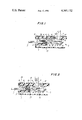
- FIG. 1 is a sketch of a side view of the plug and mechanical interlock system of this invention in an "on" position.
- FIG. 2 is a sketch of a side view of the plug and mechanical interlock system of this invention in the "off" position.
- FIGS. 1 and 2 The embodiment of the invention as illustrated by FIGS. 1 and 2 has a female socket 12 which is part of the appliance housing 18 and contains electric contacts 13 which are electrically attached by conventional wiring, not shown, to a three position power switch 3 in the housing, said power switch 3 has a sliding control member 16 attached thereto which extends longitudinally into the female socket 12.
- a cover plate 5 on the power switch 3 has an extension 8 which extends longitudinally into the socket 12.
- the extension 8 has on its surface toward the inside longitudinal axis of the socket 12 a strip of spring metal 9 biased radially toward the center of the socket 12.
- At the end of the spring metal strip 9 toward the back of the socket 12 is a pin 10 on the face of the strip 9 which faces the longitudinal axis of the socket 12.
- the switch cover plate 5 has a longitudinal opening 15 for accommodating the thumb button control 7 which is attached to the top of the sliding control member 16.
- bosses 6 on the underside of the switch cover plate 5 at each control position in the cover plate 5 which act as stops to stop the thumb button 7 from moving too far when it is pushed longitudinally toward or away from the socket 12 and thus control the current.
- FIGS. 1 and 2 there is a boss 6 at position A, the "off" position, position B, the "low” position, and position C, the "high” position; the bosses 6 for position B are shown in dotted lines since they are at the side of the opening 15.
- the sliding control member 16 is slidably attached to the switch 3 by a boss 19 projecting from the switch 3 into a longitudinal groove or track on the underside of the sliding control member.
- An extension 4 of the sliding control member 16 extends longitudinally toward the socket 12, and has a wedge shaped end 20.
- the end 20 of the extension 4 slides under and radially lifts the spring metal strip 9 with the pin 10 toward the inside surface of the socket 12 away from the longitudinal axis thereof. This enables a male plug to either be inserted or removed.
- the male plug 1 which is used in this invention comprises electrical contacts 17 connected to an alternating current power cord 2.
- the connection is insulated with elastomeric insulation formed to have an indentation 11 situated so that it can receive the pin 10 of the spring metal bar 9 when inserted into the socket 12.
- the electrical contacts 17 protrude from the insulated plug 1 and contact the electrical contacts 13 in the socket 12 when inserted therein.
- the plug 1 can receive the pin 10 only when the sliding control member 16 is in an "on” position, since it is in the "on” position that the spring metal bar 9 is released from the lifting pressure of the slide extension 4 and can lock the plug into position.
- the plug 1 can only be inserted into or removed from the socket 12 when the sliding control member 16 is in the "off" position.
- the pin 10 When in an "on” position, the pin 10 will block the plug 1 from entering the socket 12 or from being removed from the socket 12. Since it is possible to remove or insert the plug into the socket 12 only when the appliance is off, no arcing can occur as happens when a plug can be removed when an appliance is turned on.
Landscapes
- Details Of Connecting Devices For Male And Female Coupling (AREA)
Abstract
Description
Claims (2)
Priority Applications (1)
| Application Number | Priority Date | Filing Date | Title |
|---|---|---|---|
| US06/258,063 US4345122A (en) | 1981-04-27 | 1981-04-27 | Detachable cord |
Applications Claiming Priority (1)
| Application Number | Priority Date | Filing Date | Title |
|---|---|---|---|
| US06/258,063 US4345122A (en) | 1981-04-27 | 1981-04-27 | Detachable cord |
Publications (1)
| Publication Number | Publication Date |
|---|---|
| US4345122A true US4345122A (en) | 1982-08-17 |
Family
ID=22978947
Family Applications (1)
| Application Number | Title | Priority Date | Filing Date |
|---|---|---|---|
| US06/258,063 Expired - Lifetime US4345122A (en) | 1981-04-27 | 1981-04-27 | Detachable cord |
Country Status (1)
| Country | Link |
|---|---|
| US (1) | US4345122A (en) |
Cited By (16)
| Publication number | Priority date | Publication date | Assignee | Title |
|---|---|---|---|---|
| US5198627A (en) * | 1991-08-09 | 1993-03-30 | Tandem Computers Incorporated | Electronic module switch and power and interlock system |
| US6280211B1 (en) * | 2000-06-08 | 2001-08-28 | Art K. Tateishi | Wall mounted heater fan with electrical outlet |
| US6554646B1 (en) | 1998-12-14 | 2003-04-29 | Berg Electronics Group, Inc. | Electrical connector assembly |
| US20100144187A1 (en) * | 2007-03-14 | 2010-06-10 | Zonit Structured Solutions, Llc | Locking electrical receptacle |
| US20100210130A1 (en) * | 2009-02-19 | 2010-08-19 | Japan Aviation Electronics Industry, Limited | Connector assembly |
| US20110177711A1 (en) * | 2008-09-30 | 2011-07-21 | Inp. Co., Ltd. | Arc-preventing apparatus for separate cord-type hair dryer |
| US20110312207A1 (en) * | 2008-03-14 | 2011-12-22 | Zonit Structured Solutions, Llc | Locking electrical receptacle |
| US20120034807A1 (en) * | 2010-08-04 | 2012-02-09 | Powertech Industrial Co., Ltd. | Detachment-preventing plug |
| WO2012125207A1 (en) * | 2011-03-15 | 2012-09-20 | Tyco Electronics Corporation | High voltage connector assembly |
| US9853400B1 (en) | 2016-11-01 | 2017-12-26 | International Business Machines Corporation | Electrical arc protection using a trip jumper |
| US9893455B1 (en) | 2016-11-01 | 2018-02-13 | International Business Machines Corporation | Electrical arc protection using a trip contact |
| US10122123B1 (en) | 2017-07-07 | 2018-11-06 | International Business Machines Corporation | Electrical arc protection using a rotational shield |
| US10256571B2 (en) | 2008-03-14 | 2019-04-09 | Zonit Structured Solutions, Llc | Locking electrical receptacle |
| US10944212B1 (en) * | 2019-12-27 | 2021-03-09 | Liang Light Chen | Power connector with anti-disengaging mechanism |
| US20210166898A1 (en) * | 2018-11-20 | 2021-06-03 | Leviton Manufacturing Co., Inc. | Mechanical interlock with enhanced features |
| US11581682B2 (en) | 2013-03-15 | 2023-02-14 | Zonit Structured Solutions, Llc | Frictional locking receptacle with programmable release |
Citations (4)
| Publication number | Priority date | Publication date | Assignee | Title |
|---|---|---|---|---|
| US621860A (en) * | 1899-03-28 | Looping-in switch | ||
| US1612711A (en) * | 1923-04-28 | 1926-12-28 | Hugo Tillquist | Electrical switch |
| US1924691A (en) * | 1931-01-02 | 1933-08-29 | Ralco Mfg Company | Safety switch |
| US2015543A (en) * | 1933-07-21 | 1935-09-24 | Crouse Hinds Co | Interlocked explosionproof switch housing and plug receptacle |
-
1981
- 1981-04-27 US US06/258,063 patent/US4345122A/en not_active Expired - Lifetime
Patent Citations (4)
| Publication number | Priority date | Publication date | Assignee | Title |
|---|---|---|---|---|
| US621860A (en) * | 1899-03-28 | Looping-in switch | ||
| US1612711A (en) * | 1923-04-28 | 1926-12-28 | Hugo Tillquist | Electrical switch |
| US1924691A (en) * | 1931-01-02 | 1933-08-29 | Ralco Mfg Company | Safety switch |
| US2015543A (en) * | 1933-07-21 | 1935-09-24 | Crouse Hinds Co | Interlocked explosionproof switch housing and plug receptacle |
Cited By (30)
| Publication number | Priority date | Publication date | Assignee | Title |
|---|---|---|---|---|
| US5198627A (en) * | 1991-08-09 | 1993-03-30 | Tandem Computers Incorporated | Electronic module switch and power and interlock system |
| US6733339B2 (en) * | 1997-03-07 | 2004-05-11 | Berg Technology, Inc. | Shielded connector with integral latching and ground structure |
| US6554646B1 (en) | 1998-12-14 | 2003-04-29 | Berg Electronics Group, Inc. | Electrical connector assembly |
| US6280211B1 (en) * | 2000-06-08 | 2001-08-28 | Art K. Tateishi | Wall mounted heater fan with electrical outlet |
| US8152554B2 (en) * | 2007-03-14 | 2012-04-10 | Zonit Structured Solutions, Llc | Locking electrical receptacle |
| US20100144187A1 (en) * | 2007-03-14 | 2010-06-10 | Zonit Structured Solutions, Llc | Locking electrical receptacle |
| US20110312207A1 (en) * | 2008-03-14 | 2011-12-22 | Zonit Structured Solutions, Llc | Locking electrical receptacle |
| US10256571B2 (en) | 2008-03-14 | 2019-04-09 | Zonit Structured Solutions, Llc | Locking electrical receptacle |
| US9065207B2 (en) * | 2008-03-14 | 2015-06-23 | Zonit Structured Solutions, Llc | Locking electrical receptacle |
| US20110177711A1 (en) * | 2008-09-30 | 2011-07-21 | Inp. Co., Ltd. | Arc-preventing apparatus for separate cord-type hair dryer |
| US8382505B2 (en) * | 2008-09-30 | 2013-02-26 | Inp. Co., Ltd. | Arc-preventing apparatus for separate cord-type hair dryer |
| US8075324B2 (en) * | 2009-02-19 | 2011-12-13 | Japan Aviation Electronics Industry, Limited | Connector assembly having a detection switch which is closed or opened by operation of a locking member |
| US20100210130A1 (en) * | 2009-02-19 | 2010-08-19 | Japan Aviation Electronics Industry, Limited | Connector assembly |
| US10998676B2 (en) | 2010-04-15 | 2021-05-04 | Zonit Structured Solutions Llc | Frictional locking receptacle with programmable release |
| US10326240B2 (en) | 2010-04-15 | 2019-06-18 | Zonit Structured Solutions, Llc | Frictional locking receptacle with programmable release |
| US20120034807A1 (en) * | 2010-08-04 | 2012-02-09 | Powertech Industrial Co., Ltd. | Detachment-preventing plug |
| US8287298B2 (en) * | 2010-08-04 | 2012-10-16 | Powertech Industrial Co., Ltd. | Detachment-preventing plug |
| US8597043B2 (en) | 2011-03-15 | 2013-12-03 | Tyco Electronics Corporation | High voltage connector assembly |
| CN103430396A (en) * | 2011-03-15 | 2013-12-04 | 泰科电子公司 | High Voltage Connector Assembly |
| WO2012125207A1 (en) * | 2011-03-15 | 2012-09-20 | Tyco Electronics Corporation | High voltage connector assembly |
| US11581682B2 (en) | 2013-03-15 | 2023-02-14 | Zonit Structured Solutions, Llc | Frictional locking receptacle with programmable release |
| US12374831B2 (en) | 2013-03-15 | 2025-07-29 | Zonit Structured Solutions Llc | Frictional locking receptacle with programmable release |
| US9893455B1 (en) | 2016-11-01 | 2018-02-13 | International Business Machines Corporation | Electrical arc protection using a trip contact |
| US10230193B2 (en) | 2016-11-01 | 2019-03-12 | International Business Machines Corporation | Electrical arc protection using a trip contact |
| US10229806B2 (en) | 2016-11-01 | 2019-03-12 | International Business Machines Corporation | Electrical arc protection using a trip jumper |
| US9853400B1 (en) | 2016-11-01 | 2017-12-26 | International Business Machines Corporation | Electrical arc protection using a trip jumper |
| US10122123B1 (en) | 2017-07-07 | 2018-11-06 | International Business Machines Corporation | Electrical arc protection using a rotational shield |
| US20210166898A1 (en) * | 2018-11-20 | 2021-06-03 | Leviton Manufacturing Co., Inc. | Mechanical interlock with enhanced features |
| US11842863B2 (en) * | 2018-11-20 | 2023-12-12 | Leviton Manufacturing Co., Inc. | Mechanical interlock with enhanced features |
| US10944212B1 (en) * | 2019-12-27 | 2021-03-09 | Liang Light Chen | Power connector with anti-disengaging mechanism |
Similar Documents
| Publication | Publication Date | Title |
|---|---|---|
| US4345122A (en) | Detachable cord | |
| EP0156076B1 (en) | Adaptor comprising sliding pin carriers | |
| US3025486A (en) | Three way electric plug | |
| US5320545A (en) | Household safety receptacle | |
| US5893772A (en) | Locking mechanism for an electrical connector | |
| US5108301A (en) | Locking electrical cord connector | |
| US2735906A (en) | Avrunin | |
| JPS61183882A (en) | Electric socket apparatus | |
| GB1332982A (en) | Electrical lighting installations | |
| US4201431A (en) | Universal adaptable three-prong electrical plug | |
| EP0379259A1 (en) | Electric iron arrangement | |
| US3588411A (en) | Power tool switch and speed control with control elements mounted in recesses in the tool handle | |
| US4481388A (en) | Electrical plug with automatic shut-off feature | |
| CA1059591A (en) | Safety plug-in jack base | |
| US5244411A (en) | Electrical appliance | |
| GB2126805A (en) | Electrical plug | |
| US3691327A (en) | Circuit-closing adapter | |
| US2846530A (en) | Electrical drop cord switch operated by removable key | |
| US3168624A (en) | Explosion proof dead front electrical receptacle having microswitch means | |
| US3977751A (en) | Release mechanism for plug in-type terminals | |
| US2450336A (en) | Electrical coupling device particularly for electric heating appliance stands | |
| US4329555A (en) | Trigger operated tool handle switch | |
| US4256942A (en) | Trigger operated tool handle switch | |
| JPH07320827A (en) | Power adapter equipment | |
| US3057975A (en) | Plug connector with switch for auxiliary starting circuit |
Legal Events
| Date | Code | Title | Description |
|---|---|---|---|
| AS | Assignment |
Owner name: CLAIROL INCORPORATED, 345 PARK AVE., NEW YORK, NY Free format text: ASSIGNMENT OF ASSIGNORS INTEREST.;ASSIGNOR:JANNIELLO FRANK;REEL/FRAME:003881/0640 Effective date: 19810420 Owner name: CLAIROL INCORPORATED, A CORP. OF DE, NEW YORK Free format text: ASSIGNMENT OF ASSIGNORS INTEREST;ASSIGNOR:JANNIELLO FRANK;REEL/FRAME:003881/0640 Effective date: 19810420 |
|
| STCF | Information on status: patent grant |
Free format text: PATENTED CASE |
|
| FEPP | Fee payment procedure |
Free format text: PAYOR NUMBER ASSIGNED (ORIGINAL EVENT CODE: ASPN); ENTITY STATUS OF PATENT OWNER: LARGE ENTITY |
|
| MAFP | Maintenance fee payment |
Free format text: PAYMENT OF MAINTENANCE FEE, 4TH YEAR, PL 96-517 (ORIGINAL EVENT CODE: M170); ENTITY STATUS OF PATENT OWNER: LARGE ENTITY Year of fee payment: 4 |
|
| MAFP | Maintenance fee payment |
Free format text: PAYMENT OF MAINTENANCE FEE, 8TH YEAR, PL 96-517 (ORIGINAL EVENT CODE: M171); ENTITY STATUS OF PATENT OWNER: LARGE ENTITY Year of fee payment: 8 |
|
| MAFP | Maintenance fee payment |
Free format text: PAYMENT OF MAINTENANCE FEE, 12TH YEAR, LARGE ENTITY (ORIGINAL EVENT CODE: M185); ENTITY STATUS OF PATENT OWNER: LARGE ENTITY Year of fee payment: 12 |
|
| AS | Assignment |
Owner name: PROVIDENT BANK, AGENT, THE, OHIO Free format text: SECURITY INTEREST;ASSIGNOR:REMINGTON PRODUCTS COMPANY;REEL/FRAME:006842/0702 Effective date: 19931224 Owner name: REMINGTON PRODUCTS COMPANY, CONNECTICUT Free format text: ASSIGNMENT OF ASSIGNORS INTEREST;ASSIGNOR:CLAIROL INCORPORATED;REEL/FRAME:006842/0900 Effective date: 19931224 |
|
| AS | Assignment |
Owner name: CHEMICAL BANK, NEW YORK Free format text: SECURITY AGREEMENT;ASSIGNOR:REMINGTON CORPORATION, L.L.C.;REEL/FRAME:007991/0259 Effective date: 19960523 |
|
| AS | Assignment |
Owner name: REMINGTON PRODUCTS COMPANY, CONNECTICUT Free format text: RELEASE BY SECURED PARTY;ASSIGNOR:PROVIDENT BANK, THE;REEL/FRAME:007991/0223 Effective date: 19960523 Owner name: REMINGTON CORPORATION, LLC, CONNECTICUT Free format text: ASSIGNMENT OF ASSIGNORS INTEREST;ASSIGNOR:REMINGTON PRODUCTS COMPANY;REEL/FRAME:007991/0367 Effective date: 19960523 |
|
| AS | Assignment |
Owner name: REMINGTON CORPORATION, L.L.C., CONNECTICUT Free format text: RELEASE;ASSIGNOR:CHASE MANHATTAN BANK, AS AGENT, THE;REEL/FRAME:012090/0794 Effective date: 20010821 |