US4338077A - Method for controlling temperature of multi-zone heating furnace - Google Patents
Method for controlling temperature of multi-zone heating furnace Download PDFInfo
- Publication number
- US4338077A US4338077A US06/210,830 US21083080A US4338077A US 4338077 A US4338077 A US 4338077A US 21083080 A US21083080 A US 21083080A US 4338077 A US4338077 A US 4338077A
- Authority
- US
- United States
- Prior art keywords
- furnace
- temperature
- heated
- controlling
- zones
- Prior art date
- Legal status (The legal status is an assumption and is not a legal conclusion. Google has not performed a legal analysis and makes no representation as to the accuracy of the status listed.)
- Expired - Lifetime
Links
Images


Classifications
-
- C—CHEMISTRY; METALLURGY
- C21—METALLURGY OF IRON
- C21D—MODIFYING THE PHYSICAL STRUCTURE OF FERROUS METALS; GENERAL DEVICES FOR HEAT TREATMENT OF FERROUS OR NON-FERROUS METALS OR ALLOYS; MAKING METAL MALLEABLE, e.g. BY DECARBURISATION OR TEMPERING
- C21D11/00—Process control or regulation for heat treatments
-
- C—CHEMISTRY; METALLURGY
- C21—METALLURGY OF IRON
- C21D—MODIFYING THE PHYSICAL STRUCTURE OF FERROUS METALS; GENERAL DEVICES FOR HEAT TREATMENT OF FERROUS OR NON-FERROUS METALS OR ALLOYS; MAKING METAL MALLEABLE, e.g. BY DECARBURISATION OR TEMPERING
- C21D9/00—Heat treatment, e.g. annealing, hardening, quenching or tempering, adapted for particular articles; Furnaces therefor
- C21D9/0081—Heat treatment, e.g. annealing, hardening, quenching or tempering, adapted for particular articles; Furnaces therefor for slabs; for billets
-
- F—MECHANICAL ENGINEERING; LIGHTING; HEATING; WEAPONS; BLASTING
- F27—FURNACES; KILNS; OVENS; RETORTS
- F27B—FURNACES, KILNS, OVENS OR RETORTS IN GENERAL; OPEN SINTERING OR LIKE APPARATUS
- F27B9/00—Furnaces through which the charge is moved mechanically, e.g. of tunnel type; Similar furnaces in which the charge moves by gravity
- F27B9/30—Details, accessories or equipment specially adapted for furnaces of these types
- F27B9/40—Arrangements of controlling or monitoring devices
-
- G—PHYSICS
- G05—CONTROLLING; REGULATING
- G05D—SYSTEMS FOR CONTROLLING OR REGULATING NON-ELECTRIC VARIABLES
- G05D23/00—Control of temperature
- G05D23/19—Control of temperature characterised by the use of electric means
- G05D23/1917—Control of temperature characterised by the use of electric means using digital means
-
- G—PHYSICS
- G05—CONTROLLING; REGULATING
- G05D—SYSTEMS FOR CONTROLLING OR REGULATING NON-ELECTRIC VARIABLES
- G05D23/00—Control of temperature
- G05D23/19—Control of temperature characterised by the use of electric means
- G05D23/1927—Control of temperature characterised by the use of electric means using a plurality of sensors
- G05D23/193—Control of temperature characterised by the use of electric means using a plurality of sensors sensing the temperaure in different places in thermal relationship with one or more spaces
- G05D23/1932—Control of temperature characterised by the use of electric means using a plurality of sensors sensing the temperaure in different places in thermal relationship with one or more spaces to control the temperature of a plurality of spaces
- G05D23/1934—Control of temperature characterised by the use of electric means using a plurality of sensors sensing the temperaure in different places in thermal relationship with one or more spaces to control the temperature of a plurality of spaces each space being provided with one sensor acting on one or more control means
-
- F—MECHANICAL ENGINEERING; LIGHTING; HEATING; WEAPONS; BLASTING
- F27—FURNACES; KILNS; OVENS; RETORTS
- F27D—DETAILS OR ACCESSORIES OF FURNACES, KILNS, OVENS OR RETORTS, IN SO FAR AS THEY ARE OF KINDS OCCURRING IN MORE THAN ONE KIND OF FURNACE
- F27D19/00—Arrangements of controlling devices
- F27D2019/0006—Monitoring the characteristics (composition, quantities, temperature, pressure) of at least one of the gases of the kiln atmosphere and using it as a controlling value
- F27D2019/0018—Monitoring the temperature of the atmosphere of the kiln
-
- F—MECHANICAL ENGINEERING; LIGHTING; HEATING; WEAPONS; BLASTING
- F27—FURNACES; KILNS; OVENS; RETORTS
- F27D—DETAILS OR ACCESSORIES OF FURNACES, KILNS, OVENS OR RETORTS, IN SO FAR AS THEY ARE OF KINDS OCCURRING IN MORE THAN ONE KIND OF FURNACE
- F27D19/00—Arrangements of controlling devices
- F27D2019/0028—Regulation
- F27D2019/0034—Regulation through control of a heating quantity such as fuel, oxidant or intensity of current
- F27D2019/004—Fuel quantity
Definitions
- This invention relates to temperature control of a furnace and more particularly, to a method of controlling a temperature of a heating furnace used for slabs prior to a hot rolling mill when the slabs having different temperature elevation patterns are continuously carried into the furnace.
- control of the furnace temperature is effected generally in such a manner that the slabs carried into the furnace attain a target temperature before they are withdrawn from the furnace.
- temperature control methods there is a method which determines a temperature elevation pattern to the slabs with respect to their positions inside the furnace, and which performs heating of the slabs in accordance with this temperature elevation pattern it is surmised that this temperature elevation pattern varies with the charging temperature of the slabs, the target withdrawing temperature, the target withdrawing temperature, the residence time of the slabs in the furnace and their materials (kind of steel).
- the initial temperature of the slabs for example, varies markedly, as will be described next.
- semi-finished metal products e.g., slabs or thick plates
- a storage zone called a steel bay until it is necessary to roll them.
- the slab temperature is substantially equal to the ambient temperature.
- cold slabs unavoidably mix with the hot slabs for rolling when the slabs are carried to the furnace after their surface correction or when the requested kinds of products are different from the kinds of slabs supplied from the continuous casting line.
- the temperature elevation pattern to the target temperature for heating the hot materials is different from that for heating the cold materials.
- the present invention relates to a method of controlling the furnace temperature of a furnace when the materials having different temperature elevation patterns such as the abovementioned hot and cold materials are continuously carried into the heating furnace.
- a primary object of the present invention is to provide a novel method of controlling the temperature of a heating furnace into which slabs having different temperature elevation patterns are being carried.
- the present invention is charcterized in that when introduction of slabs having a different temperature elevation pattern is detected during introduction of slabs into a heating furnace, the set temperature of the heating furnace is changed over afresh to a value suited for the slabs introduced subsequently.
- the set value for each zone of the furnace is changed over at a timing corresponding to the movement of a leading slab of a group of slabs having a different temperature elevation pattern.
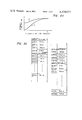
- FIG. 1 is a block diagram of the construction of the heating furnace and the control system
- FIG. 2A shows an example of the temperature elevation pattern for the hot materials and FIG. 2B shows the block diagram of the set temperature calculation apparatus for the furnace in accordance with the present invention
- FIG. 3A shows an example of the tracking file memory
- FIG. 3B shows an example of the data structure per slab of the file memory
- FIG. 3C shows an example of the set value memory
- FIG. 4 shows an example of the temperature elevation patterns for the hot material and the cold material
- FIG. 5 shows an example of the response time of the furnace zone
- FIGS. 6A and 6C show the timings for changing the set values with respect to the slab positions
- FIG. 7 shows examples of the set values corresponding to each zone for the hot material and for the cold material
- FIG. 8(a) shows the furnace zones
- FIGS. 8(b) through 8(e) show the positions of the corresponding slabs
- FIGS. 8(f) through 8(j) show the timing for the set temperatures
- FIGS. 8(k) and 8(l) show the timings for releasing the lock on the set values
- FIG. 9 shows the flow chart for practising the method of the present invention by use of a computer.
- FIG. 1 shows diagrammatically the construction of a heating furnace and the control system in accordance with the present invention.
- Reference numeral 1 represents the heating furnace as a whole.
- the heating furnace is a 4-zone type heating furnace in which I represents a preheating zone, II and III represent heating zones and IV a soaking zone.
- Reference numerals 3-1 through 3-4 represent furnace zone temperature detectors that are provided in the respective zones.
- Reference numerals 4-1 through 4-4 represent fuel burners provided in the respective zones and 5-1 through 5-4 represent minor furnace temperature controllers.
- Reference numerals 6-1 through 6-4 represent operational devices for determining the difference between the furnace temperatures detected by the detectors 3-1 through 3-4 and furnace temperature set values T P (Tp-1 through Tp-4), respectively.
- Reference numerals 7-1 through 7-4 represent fuel flow controllers that control the fuel flow F, respectively.
- Reference numeral 200 represents a furnace temperature control system while reference numeral 9 represents an exhaust stack.
- Reference numeral 2 represents a slab to be heated.
- FIG. 1 shows a 4-zone type heating furnace in which the temperature control for each zone I through IV is independently carried out.
- the fuel control is effected by the fuel flow controllers (7-1 through 7-4) in such a fashion that the actual furnace temperature in each zone coincides with the output (Tp-1 through Tp-4) from the control system for setting the furnace temperature 200.
- Symbol F represents a fuel and F 1 through F 4 represent fuel flow in the zones I through IV, respectively.
- the conventional apparatus for setting the furnace temperature calculates the value of the slab temperature in the furnace using the temperature detection values T1-T4 in the zones and adjusts the setting value of the furnace temperature so that the difference between the target value determined by the temperature elevation pattern of the slab and the slab temperature is minimized.
- the response speed of the furnace temperature control is affected by the change speed of the slab temperature.
- the time constant of this slab temperature is frequently in the order of scores of minutes so that the furnace temperature control is effected slowly in accordance with the constant.
- the system is suited for stable control when materials having substantially the same heating conditions ("steady states”) are to be heated, but when materials having remarkably different heating conditions (“unsteady states”) are to be heated, the control accuracy of the slab temperature is markedly deteriorated due to the response delay.
- FIG. 2A shows examples of the temperature elevation patterns of such hot and cold materials.
- the atmosphere inside the furnace is controlled at first in such a manner as to heat the hot material along the curve H in FIG. 2A because the great majority of the steel plates in the furnace are the hot materials at the beginning.
- the temperature of the atmosphere inside the furnace so as to be suitable for heating the cold materials.
- heating along the curve C in FIG. 2A becomes necessary.
- a critical problem here is that the control accuracy of the slabs before and after the boundary slab drops when the temperature atmosphere inside the furnace is thus changed.
- the hot charge materials are heated with the temperature pattern for the cold materials, they are over-heated while if the cold charge materials are heated with the temperature elevation pattern for the hot charge materials, they are heated insufficient heating, it is necessary to bring the furnace temperature close to the optimum value of each material as rapidly as possible.
- the furnace temperature correction is effected by means of the time constant of change of the slab temperature as described above, over-heating or insufficient heating of the slab unavoidably occurs.
- FIG. 2B is a block diagram of the control system 200 for setting the furnace temperature for explaining the present invention.
- reference numeral 3(3-1 through 3-4) represents a furnace temperature detector
- 4(4-1 through 4-4) is a burner for supplying an air-fuel mixture
- 5(5-1 through 5-4) is a minor controller, as in FIG. 1.
- Reference 202 represents a memory for tracking the slabs inside the furnace and forms a data file in accordance with each slab position. It is a memory file which detects the movement of a walking beam (or pusher) by an operation pitch detector S and shifts the memory content in the direction represented by arrow D such as shown in FIG. 3A, for example.
- This memory file enables an operator of the furnace to ascertain which slab is now located at which position inside the furnace.
- the data for a slab or slabs withdrawn from the furnace is deleted from the file but this data can be used for other tracking purposes on rolling lines subsequent to the furnace output.
- FIG. 3A diagrammatically shows the case where hot materials H are first charged and then cold materials C are charged, followed by another group of hot materials H.
- Symbols C and H represent the leading cold and hot materials, respectively, and they are hereinafter called "boundary slabs". Even when slabs are carried into the furnace while the furnace is empty, the leading slabs are called the "boundary slabs".
- a catalog to the tracking file is made as the operator instructs the catalog to the file when the slabs are carried into the furnace.
- automatic registration may be made including distinction of the hot materials from the cold materials by means of slab temperature detectors disposed at the furnace inlet.
- Reference numeral 204 represents a slab position calculator which manages the slabs by means of the slab position data of the aforementioned tracking file, charge classification data and sitrinction data between the hot materials and the cold materials. These slab data are memorized by alloting each bit to the data as shown in FIG. 3B, for example. Namely, FIG. 3B shows case where 16 bits are alloted to each slab, and the tracking file data are also the abovementioned three kinds. If necessary, however, other data may also be added.
- the slab position calculator 204 manages the slabs inside the furnace on the basis of the file data.
- the aforementioned boundary slabs are C and H shown in FIG. 3A, and tracking of these boundary slabs is indispensable for correcting the temperature elevation patterns of the slab groups.
- the slab position calculator 204 calculates the distance X DC of the boundary slab C from the furnace inlet, for example, on the basis of the tracking file data, ordinarily, the number of the boundary slabs that are simultaneously present in the furnace is two at the most.
- the slab position calculator 204 further determines to which furnace zone K D the boundary slabs belong. Generally, judgement is made from the distance X D from the furnace inlet. In FIG. 3A, for example, the judgement is made in the following manner;
- L represents the entire length of the heating furnace and L 1 through L 3 represent the distances from the furnace inlet to each zone outlet, respectively.
- the slab position calculator recognizes whether the boundary slab exists or doesn't in any heating zone, and sends the information to controllers 208 and 208'. If the boundary slab doesn't exist in any zone, the set temperature of that zone is determined in the controller 208. On the other hand, if exist, it is determined in the controller 208'.
- the signal 210 represents this control selection and K D .
- the memory 206 memorizes the temperature elevation pattern of the slab.
- the target slab temperatures at 20 furnace positions in the furnace are memorized in the form such as shown in FIG. 3C.
- the values Tpc1-1 through Tpc1-20 are represented by the 20 values of the pattern C 1 .
- the memory values of these patterns are sent to the temperature controller 208 as the signal 205.
- the pattern C 1 in FIG. 3C corresponds to the temperature elevation pattern C 1 of the cold materials in FIG. 4, for example. This also holds true of the patterns C 2 , C 3 and H 1 through H 3 .
- the controller 208 is used in the steady state.
- the conventional control method can be applied to the controller 208, which is represented in commonly assigned U.S. patent application Ser. No. 28,705 (filed Apr. 10, 1979) entitled “METHOD FOR CONTROLLING FURNACE TEMPERATURE OF MULTI-ZONE HEATING FURNACE", now U.S. Pat. No. 4,255,133 (issued Mar. 10, 1981), for instance.
- optimum temperature elevation pattern which corresponds to any curve in FIG. 4, is chose from the memorized patterns in 206.
- the set temperatures of the heating zones are determined so as to make the slab temperature follow the chosen pattern.
- the output signal Tp1-4, C,H of the block 208 in FIG. 2B represents the set values of each zone temperature and they are given to the minor controller 5(1 ⁇ 4).
- the controller 208' is used in unsteady state. In other words, 208' is used, when the boundary slab exist in any heating zone.
- the memory 206 memorizes setting value of the zone temperature in the form such as shown in FIG. 3C.
- ADRC 10 , ADRC 11 . . . represent memory addresses while [Tp1]C1, [Tp2]C2 . . . represent the set temperatures in the zones corresponding to the slab elevation patterns.
- an index signal which represent the pattern, is send to the controller 208' as a signal 209.
- the controller 208' is select the setting temperature of the unsteady zone from the memory 206 according to the index signal 209. This selection is represented as 205' in FIG. 2B.
- the furnace temperature setting timing in each zone in 208' will be explained.
- the timing for setting the furnace set temperature is determined using the boundary slab position X D calculated by the aforementioned slab position calculator 204 and the furnace zone number K D to which the boundary slab belongs.
- FIG. 5 shows an example of the response of the furnace zone temperature when the set temperature TpI of the furnace zone I, is changed step-wisely by ⁇ TpI.
- the response of the furnace zone temperature T I can be regarded as a response characteristic of the first order delay including the dead time.
- the time until 90% of the change ⁇ TpI, that is, ⁇ R(I) in FIG. 5 is defined as the response time of the zone I. It is necessary to determine the timing for setting the zone temperature in consideration of this response time.
- FIG. 6B shows the timing for correcting the set temperature Tp(k+1) of the (k+1)th zone.
- FIG. 6B shows the case where Tp(k+1) is to be corrected earlier by ⁇ p(k+1) than the timing when the boundary slab arrives at the inlet of the (k+1)th zone by ⁇ p(k+1)
- FIG. 6C shows the case where Tp(k+1) is to be corrected in advance by p(k+1)/2.
- FIG. 7 shows an example of the set temperature values of the furnace zones, respectively.
- [Tp1]C through [Tp4]C represent the set temperatures for the zone 1 through 4 for the cold material and [Tp1]h through [Tp4]h likewise represent the set temperatures for the hot material.
- FIG. 8(b) shows the distribution of the slabs inside the furnace where C represents the cold material, H does the hot materials and H does the leading slab of the hot materials, that is, the boundary slab.
- FIG. 8(b) shows the state where the boundary slab enters the first zone I
- FIG. 8(f) shows the set temperature in the case where only the cold materials are present inside the furnace.
- FIG. 8(d) shows the timing for correcting the set temperature of third zone while FIG. 8(e) shows that of fourth zone.
- tracking inside the furnace is effected on the basis of the detected data and the correction of the furnace temperature is effected in advance of the slab movement in consideration of the heat response characteristic of each furnace zone at the timing shown in FIG. 8.
- t 2 represents the timing that satisfies the abovementioned relation ⁇ T1 ⁇ 1 and at this timing, the lock is released and the set value Tp1 is determined by the steady state algorithm.
- the set value for the second zone II is corrected to [Tp2]h.
- the lock release holds true also for the second through the fourth zones II-IV. They are expressed by the following general formulas, respectively: ##EQU1## Namely, the lock release is made at each of the above-mentioned timings. (In the same way as in FIG. 5, 63% response or 90% response may also be employed). The lock may be released sequentially from the first zone to the fourth zone.
- FIG. 9 A flow chart for practising the furnace zone temperature set control using a computer is shown in FIG. 9.
- the response time of the furnace temperature is defined as the 90% response, but the response time may be a 63% response. Selection of these values is determined in conjunction with the furnace operation schedule and the like. More generally, ⁇ Di of the ith zone is determined in accordance with the response of the (i+1)th zone. The optimum value should be selected in accordance with the furnace characteristics. At times, a constant value may be selected irrespective of the furnace characteristics.
Landscapes
- Engineering & Computer Science (AREA)
- Chemical & Material Sciences (AREA)
- Physics & Mathematics (AREA)
- Mechanical Engineering (AREA)
- Materials Engineering (AREA)
- Crystallography & Structural Chemistry (AREA)
- Thermal Sciences (AREA)
- Metallurgy (AREA)
- Organic Chemistry (AREA)
- General Physics & Mathematics (AREA)
- Automation & Control Theory (AREA)
- Remote Sensing (AREA)
- General Engineering & Computer Science (AREA)
- Control Of Heat Treatment Processes (AREA)
- Control Of Temperature (AREA)
Abstract
Description
when L.sub.1 <X.sub.DH <L.sub.2 →K.sub.D =II
when L.sub.2 <C.sub.DC <L.sub.3 →K.sub.D =III.
Claims (11)
Applications Claiming Priority (2)
| Application Number | Priority Date | Filing Date | Title |
|---|---|---|---|
| JP54152098A JPS5848009B2 (en) | 1979-11-26 | 1979-11-26 | Temperature control method for multi-zone heating furnace |
| JP54/152098 | 1979-11-26 |
Publications (1)
| Publication Number | Publication Date |
|---|---|
| US4338077A true US4338077A (en) | 1982-07-06 |
Family
ID=15532998
Family Applications (1)
| Application Number | Title | Priority Date | Filing Date |
|---|---|---|---|
| US06/210,830 Expired - Lifetime US4338077A (en) | 1979-11-26 | 1980-11-26 | Method for controlling temperature of multi-zone heating furnace |
Country Status (3)
| Country | Link |
|---|---|
| US (1) | US4338077A (en) |
| JP (1) | JPS5848009B2 (en) |
| DE (1) | DE3044562C2 (en) |
Cited By (19)
| Publication number | Priority date | Publication date | Assignee | Title |
|---|---|---|---|---|
| US4577278A (en) * | 1983-07-18 | 1986-03-18 | North American Manufacturing Company | Method and system for controlling a selected zone in a fuel fired furnace |
| US4606006A (en) * | 1981-10-05 | 1986-08-12 | Mitsubishi Denki K.K. | Method of controlling the rolling efficiency in hot rolling |
| US5006061A (en) * | 1987-11-11 | 1991-04-09 | Hoogovens Groep B.V. | Method for bringing a plurality of steel slabs to rolling temperature in a furnace |
| US5708678A (en) * | 1995-09-13 | 1998-01-13 | Danieli & C. Officine Meccaniche Spa | Method to equalize the temperature in a heating furnace with a controlled-oxidization ambient and heating furnace carrying out the method |
| US6332492B1 (en) * | 1997-11-11 | 2001-12-25 | Danieli & Officine Meccaniche Spa | Method to control the axial position of slabs emerging from continuous casting and relative device |
| US6336809B1 (en) | 1998-12-15 | 2002-01-08 | Consolidated Engineering Company, Inc. | Combination conduction/convection furnace |
| US20040108092A1 (en) * | 2002-07-18 | 2004-06-10 | Robert Howard | Method and system for processing castings |
| US20040259047A1 (en) * | 2001-09-06 | 2004-12-23 | Gerard Le Gouefflec | Method of improving the temperature profile of a furnace |
| US20050072549A1 (en) * | 1999-07-29 | 2005-04-07 | Crafton Scott P. | Methods and apparatus for heat treatment and sand removal for castings |
| US20050257858A1 (en) * | 2001-02-02 | 2005-11-24 | Consolidated Engineering Company, Inc. | Integrated metal processing facility |
| US20050269751A1 (en) * | 2001-02-02 | 2005-12-08 | Crafton Scott P | Integrated metal processing facility |
| US20060054294A1 (en) * | 2004-09-15 | 2006-03-16 | Crafton Scott P | Short cycle casting processing |
| US20060103059A1 (en) * | 2004-10-29 | 2006-05-18 | Crafton Scott P | High pressure heat treatment system |
| US20070082311A1 (en) * | 2005-09-16 | 2007-04-12 | Tamura Corporation | Method for controlling heating apparatus |
| US20080236779A1 (en) * | 2007-03-29 | 2008-10-02 | Crafton Scott P | Vertical heat treatment system |
| US20090269713A1 (en) * | 2007-02-28 | 2009-10-29 | Byung Gil Choi | Heat treatment equipment |
| CN112461010A (en) * | 2020-10-12 | 2021-03-09 | 首钢京唐钢铁联合有限责任公司 | Method, device and medium for reducing energy consumption of heating furnace to be rolled |
| US11408062B2 (en) | 2015-04-28 | 2022-08-09 | Consolidated Engineering Company, Inc. | System and method for heat treating aluminum alloy castings |
| EP4696967A1 (en) * | 2024-08-16 | 2026-02-18 | ThyssenKrupp Steel Europe AG | Method for heat treating a steel product |
Families Citing this family (3)
| Publication number | Priority date | Publication date | Assignee | Title |
|---|---|---|---|---|
| JPH0398798U (en) * | 1990-01-26 | 1991-10-15 | ||
| JP6035817B2 (en) * | 2012-03-30 | 2016-11-30 | Jfeスチール株式会社 | Automatic combustion control method and apparatus for continuous heating furnace |
| CN104110962B (en) * | 2014-06-23 | 2016-03-23 | 中国矿业大学(北京) | An experimental furnace for blasting equipment |
Citations (4)
| Publication number | Priority date | Publication date | Assignee | Title |
|---|---|---|---|---|
| US3604695A (en) * | 1969-12-15 | 1971-09-14 | Gen Electric | Method and apparatus for controlling a slab reheat furnace |
| US3695594A (en) * | 1969-08-13 | 1972-10-03 | Koninklijke Nederlandsche Hoogovens En Staalfabrieken Nv | Method and apparatus for operating a pusher type furnace |
| US4255133A (en) * | 1978-04-10 | 1981-03-10 | Hitachi, Ltd. | Method for controlling furnace temperature of multi-zone heating furnace |
| US4257767A (en) * | 1979-04-30 | 1981-03-24 | General Electric Company | Furnace temperature control |
-
1979
- 1979-11-26 JP JP54152098A patent/JPS5848009B2/en not_active Expired
-
1980
- 1980-11-26 US US06/210,830 patent/US4338077A/en not_active Expired - Lifetime
- 1980-11-26 DE DE3044562A patent/DE3044562C2/en not_active Expired - Lifetime
Patent Citations (4)
| Publication number | Priority date | Publication date | Assignee | Title |
|---|---|---|---|---|
| US3695594A (en) * | 1969-08-13 | 1972-10-03 | Koninklijke Nederlandsche Hoogovens En Staalfabrieken Nv | Method and apparatus for operating a pusher type furnace |
| US3604695A (en) * | 1969-12-15 | 1971-09-14 | Gen Electric | Method and apparatus for controlling a slab reheat furnace |
| US4255133A (en) * | 1978-04-10 | 1981-03-10 | Hitachi, Ltd. | Method for controlling furnace temperature of multi-zone heating furnace |
| US4257767A (en) * | 1979-04-30 | 1981-03-24 | General Electric Company | Furnace temperature control |
Cited By (32)
| Publication number | Priority date | Publication date | Assignee | Title |
|---|---|---|---|---|
| US4606006A (en) * | 1981-10-05 | 1986-08-12 | Mitsubishi Denki K.K. | Method of controlling the rolling efficiency in hot rolling |
| US4577278A (en) * | 1983-07-18 | 1986-03-18 | North American Manufacturing Company | Method and system for controlling a selected zone in a fuel fired furnace |
| US5006061A (en) * | 1987-11-11 | 1991-04-09 | Hoogovens Groep B.V. | Method for bringing a plurality of steel slabs to rolling temperature in a furnace |
| US5708678A (en) * | 1995-09-13 | 1998-01-13 | Danieli & C. Officine Meccaniche Spa | Method to equalize the temperature in a heating furnace with a controlled-oxidization ambient and heating furnace carrying out the method |
| US6332492B1 (en) * | 1997-11-11 | 2001-12-25 | Danieli & Officine Meccaniche Spa | Method to control the axial position of slabs emerging from continuous casting and relative device |
| US6336809B1 (en) | 1998-12-15 | 2002-01-08 | Consolidated Engineering Company, Inc. | Combination conduction/convection furnace |
| US6547556B2 (en) | 1998-12-15 | 2003-04-15 | Consolidated Engineering Company, Inc. | Combination conduction/convection furnace |
| US7275582B2 (en) | 1999-07-29 | 2007-10-02 | Consolidated Engineering Company, Inc. | Methods and apparatus for heat treatment and sand removal for castings |
| US20070289715A1 (en) * | 1999-07-29 | 2007-12-20 | Crafton Scott P | Methods and apparatus for heat treatment and sand removal for castings |
| US20050072549A1 (en) * | 1999-07-29 | 2005-04-07 | Crafton Scott P. | Methods and apparatus for heat treatment and sand removal for castings |
| US7338629B2 (en) | 2001-02-02 | 2008-03-04 | Consolidated Engineering Company, Inc. | Integrated metal processing facility |
| US7258755B2 (en) | 2001-02-02 | 2007-08-21 | Consolidated Engineering Company, Inc. | Integrated metal processing facility |
| US20050257858A1 (en) * | 2001-02-02 | 2005-11-24 | Consolidated Engineering Company, Inc. | Integrated metal processing facility |
| US20050269751A1 (en) * | 2001-02-02 | 2005-12-08 | Crafton Scott P | Integrated metal processing facility |
| US20080264527A1 (en) * | 2001-02-02 | 2008-10-30 | Crafton Scott P | Integrated metal processing facility |
| US7641746B2 (en) | 2001-02-02 | 2010-01-05 | Consolidated Engineering Company, Inc. | Integrated metal processing facility |
| US20040259047A1 (en) * | 2001-09-06 | 2004-12-23 | Gerard Le Gouefflec | Method of improving the temperature profile of a furnace |
| US6935856B2 (en) * | 2001-09-06 | 2005-08-30 | L'Air Liquide, Société Anonyme à Directoire et Conseil de Surveillance pour l'Etude et l'Exploitation des Procédés Georges Claude | Method of improving the temperature profile of a furnace |
| US20040108092A1 (en) * | 2002-07-18 | 2004-06-10 | Robert Howard | Method and system for processing castings |
| US6901990B2 (en) | 2002-07-18 | 2005-06-07 | Consolidated Engineering Company, Inc. | Method and system for processing castings |
| US20060054294A1 (en) * | 2004-09-15 | 2006-03-16 | Crafton Scott P | Short cycle casting processing |
| US20060103059A1 (en) * | 2004-10-29 | 2006-05-18 | Crafton Scott P | High pressure heat treatment system |
| US8663547B2 (en) | 2004-10-29 | 2014-03-04 | Consolidated Engineering Company, Inc. | High pressure heat treatment system |
| US20090206527A1 (en) * | 2004-10-29 | 2009-08-20 | Crafton Scott P | High pressure heat treatment system |
| US20070082311A1 (en) * | 2005-09-16 | 2007-04-12 | Tamura Corporation | Method for controlling heating apparatus |
| US20090269713A1 (en) * | 2007-02-28 | 2009-10-29 | Byung Gil Choi | Heat treatment equipment |
| US8182263B2 (en) * | 2007-02-28 | 2012-05-22 | Byung Gil Choi | Heat treatment equipment |
| US20080236779A1 (en) * | 2007-03-29 | 2008-10-02 | Crafton Scott P | Vertical heat treatment system |
| US11408062B2 (en) | 2015-04-28 | 2022-08-09 | Consolidated Engineering Company, Inc. | System and method for heat treating aluminum alloy castings |
| CN112461010A (en) * | 2020-10-12 | 2021-03-09 | 首钢京唐钢铁联合有限责任公司 | Method, device and medium for reducing energy consumption of heating furnace to be rolled |
| CN112461010B (en) * | 2020-10-12 | 2022-06-14 | 首钢京唐钢铁联合有限责任公司 | Method, device and medium for reducing energy consumption of heating furnace to be rolled |
| EP4696967A1 (en) * | 2024-08-16 | 2026-02-18 | ThyssenKrupp Steel Europe AG | Method for heat treating a steel product |
Also Published As
| Publication number | Publication date |
|---|---|
| DE3044562A1 (en) | 1981-09-10 |
| JPS5675529A (en) | 1981-06-22 |
| JPS5848009B2 (en) | 1983-10-26 |
| DE3044562C2 (en) | 1990-06-21 |
Similar Documents
| Publication | Publication Date | Title |
|---|---|---|
| US4338077A (en) | Method for controlling temperature of multi-zone heating furnace | |
| US4257767A (en) | Furnace temperature control | |
| US4255133A (en) | Method for controlling furnace temperature of multi-zone heating furnace | |
| US4373364A (en) | Method of controlling the temperature of a heating furnace | |
| US4239483A (en) | Method of controlling steel strip temperature in continuous heating equipment | |
| US4087238A (en) | Method for enhancing the heating efficiency of continuous slab reheating furnaces | |
| US3628358A (en) | Method of revising workpiece temperature estimates or measurements using workpiece deformation behavior | |
| JP2809925B2 (en) | Sheet temperature control method for continuous annealing furnace | |
| JPH0160530B2 (en) | ||
| JP3982042B2 (en) | Combustion control method for continuous heating furnace | |
| US4709570A (en) | Method for setting steel stock discharge temperature of heating furnace in hot rolling line | |
| JPH076001B2 (en) | Furnace temperature setting device for continuous heating furnace | |
| JPH08246058A (en) | Automatic combustion control method in continuous heating furnace | |
| JPS5812325B2 (en) | Control method for continuous heating furnace | |
| JP4815837B2 (en) | Combustion control method for continuous heating furnace | |
| JPS6345454B2 (en) | ||
| Andreev et al. | Obtaining reliable information on energy-saving regimes for the heating of continuous-cast semifinished products prior to rolling | |
| JPH032213B2 (en) | ||
| JPH06306453A (en) | Skid mark erasing method in continuous heating furnace | |
| Kamata et al. | Computer control system for continuous reheating furnace | |
| JPH08283860A (en) | Slab heating furnace distribution schedule creation method and apparatus | |
| JPH0684867B2 (en) | Furnace temperature setting device for continuous heating furnace | |
| JPS6051534B2 (en) | Method for controlling the conveyance speed of objects to be heated in a continuous heating furnace | |
| JPS582247B2 (en) | Continuous heating furnace control method | |
| JPH0361726B2 (en) |
Legal Events
| Date | Code | Title | Description |
|---|---|---|---|
| AS | Assignment |
Owner name: NIPPON KOKAN KABUSHIKI KAISHA, 1-2, MARUNOUCHI 1-C Free format text: ASSIGNMENT OF ASSIGNORS INTEREST.;ASSIGNORS:SHIBAYAMA, HIROSHI;TANIFUJI, SHINYA;MOROOKA, YASUO;AND OTHERS;REEL/FRAME:003948/0151 Effective date: 19801107 Owner name: HITACHI, LTD., 5-1, MARUNOUCHI 1-CHOME, CHIYODA-KU Free format text: ASSIGNMENT OF ASSIGNORS INTEREST.;ASSIGNORS:SHIBAYAMA, HIROSHI;TANIFUJI, SHINYA;MOROOKA, YASUO;AND OTHERS;REEL/FRAME:003948/0151 Effective date: 19801107 Owner name: NIPPON KOKAN KABUSHIKI KAISHA, A CORP. OF JAPAN,JA Free format text: ASSIGNMENT OF ASSIGNORS INTEREST;ASSIGNORS:SHIBAYAMA, HIROSHI;TANIFUJI, SHINYA;MOROOKA, YASUO;AND OTHERS;REEL/FRAME:003948/0151 Effective date: 19801107 Owner name: HITACHI, LTD., A CORP. OF JAPAN,JAPAN Free format text: ASSIGNMENT OF ASSIGNORS INTEREST;ASSIGNORS:SHIBAYAMA, HIROSHI;TANIFUJI, SHINYA;MOROOKA, YASUO;AND OTHERS;REEL/FRAME:003948/0151 Effective date: 19801107 Owner name: HITACHI, LTD., A CORP. OF JAPAN, JAPAN Free format text: ASSIGNMENT OF ASSIGNORS INTEREST;ASSIGNORS:SHIBAYAMA, HIROSHI;TANIFUJI, SHINYA;MOROOKA, YASUO;AND OTHERS;REEL/FRAME:003948/0151 Effective date: 19801107 |
|
| STCF | Information on status: patent grant |
Free format text: PATENTED CASE |