US433147A - System of temperature-regulation - Google Patents
System of temperature-regulation Download PDFInfo
- Publication number
- US433147A US433147A US433147DA US433147A US 433147 A US433147 A US 433147A US 433147D A US433147D A US 433147DA US 433147 A US433147 A US 433147A
- Authority
- US
- United States
- Prior art keywords
- valve
- steam
- pipe
- trap
- radiator
- Prior art date
- Legal status (The legal status is an assumption and is not a legal conclusion. Google has not performed a legal analysis and makes no representation as to the accuracy of the status listed.)
- Expired - Lifetime
Links
- XLYOFNOQVPJJNP-UHFFFAOYSA-N water Substances O XLYOFNOQVPJJNP-UHFFFAOYSA-N 0.000 description 16
- 238000004891 communication Methods 0.000 description 15
- 230000006854 communication Effects 0.000 description 15
- 230000005494 condensation Effects 0.000 description 8
- 238000009833 condensation Methods 0.000 description 8
- 238000010276 construction Methods 0.000 description 4
- 230000001276 controlling effect Effects 0.000 description 3
- 230000001105 regulatory effect Effects 0.000 description 3
- 210000002445 nipple Anatomy 0.000 description 2
- 230000001174 ascending effect Effects 0.000 description 1
- 150000001875 compounds Chemical class 0.000 description 1
- 239000012809 cooling fluid Substances 0.000 description 1
- 230000002349 favourable effect Effects 0.000 description 1
- 238000010438 heat treatment Methods 0.000 description 1
- 230000002452 interceptive effect Effects 0.000 description 1
- JEIPFZHSYJVQDO-UHFFFAOYSA-N iron(III) oxide Inorganic materials O=[Fe]O[Fe]=O JEIPFZHSYJVQDO-UHFFFAOYSA-N 0.000 description 1
- 238000004519 manufacturing process Methods 0.000 description 1
- 239000002245 particle Substances 0.000 description 1
Images


Classifications
-
- F—MECHANICAL ENGINEERING; LIGHTING; HEATING; WEAPONS; BLASTING
- F24—HEATING; RANGES; VENTILATING
- F24D—DOMESTIC- OR SPACE-HEATING SYSTEMS, e.g. CENTRAL HEATING SYSTEMS; DOMESTIC HOT-WATER SUPPLY SYSTEMS; ELEMENTS OR COMPONENTS THEREFOR
- F24D1/00—Steam central heating systems
Definitions
- My invention relates to certain new and useful improvements in systems of regulating temperature by the circulation of a heating or cooling fluid, and is particularly designed for the distribution of heat by means of steam or the like from a central point in a building to a series of distant apartments.
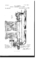
- Figure 1 represents the general arrangement of a system of radiators, supply and return pipes, steam-generator, and accessories embodying my invention.
- Fig. 2 represents, ona larger scale, one of the radiators with its regulatingvalve and pipe-connections.
- Fig. 3 represents in detail, partly in section, my preferred construction of steam-trap for returning the water of condensation to the boiler.
- Fig. ere presents in detail elevation the hot watenwell steam-trap
- Fig. 5 represents a cross-see tion of the same on a plane indicated by the line 5 5 of Fig. 1.
- the steam-supply is derived from a generator of any convenient construction adapted for the ready production of a sufficient quantity of steam under the requisite pressure to meet the needs of the distributing system employed.
- the steam-boiler dome 2 as provided with an exit-pipe 3, surmounted by the usual safety-valve 4, and communicating by a T-connection with a cross-pipe 6, said cross-pipe having the usual shut-off globevalve 7, and supplying the main distributingpipe 8 of the system.
- a pressure regulating or reducing valve 9 which valve, as will hereinafter appear, discharges important functions in the general system.
- a descending branch 10 having a globe-valve or shut-off 11, connects with the steam-trap 12, suitably mounted, as shown, and provided with the water-level gage 13 and the airvalve let.
- the branch 10 is provided with an automatic cut-ofi 15, (preferably of the kind illustrated in Fig. 1 of the joint application of Joseph Robison and myself for improvements in valves, filed August 31, 1888,
- a pipe 18 From the upper portion of the trap 12 extends a pipe 18, provided with a check-valve 19, and entering the hot-water-well steamtrap 20 to near the bottom thereof, as indicated in dotted lines in Fig. 1.
- a pipe 21 From the upper portion of said trap 20 a pipe 21 communicates with the main steam-pipe e.
- the pipe 21 communicates also with the return or drip piping from the various radiators, said communication taking place through the intermediacy of a two-way valve 22, preferably of the kind illustrated in Fig. 2 of the joint application of Robison and Pratt, hereinbefore referred to.
- valve-stem in this instance is so connected with the float in the trap 20 that except when the float 77 is in its highest position communication between the pipe 21 and trap 20 will be cut off, while between the return-piping and trap 20 it will be open. ⁇ Vhen the float '77, however, is in its highest position, these conditions will be reversed, so that communication between the return-piping and trap 20 will be cut off and between the pipe 21 and trap 20 will be open.
- the main distributing-pipe 8 above the reducing-valve 9 extends to the radiators lo cated in the Various apartments to be heated by means of an ascending pipe, which may, as shown, extend directly to a bank of coils or radiator 25 in the uppermost apartment, which radiator connects by return -piping with a series of radiators 26, 35, and 36, and finally with the trap 20.
- a branch 37 from the main distributing-pipe 8 leads to the uppermost radiator of a second series, as 38 39, which by a return-pipe 40 finally communicates with the return-pipe of the first series, so that bothreturn-pipes have a common outlet into the trap 20 through the valve 22.
- each radiator is located one of the twoway Robison-Pratt valves, as indicated by the numerals 28, 32, 33, 34, 41, and 42 in Fig. 1.
- the function of each of these valves is to direct the steam either through the particular radiator to which it is attached, so as to heat the same, or through a by-pass pipe, so as not to enter said radiator, the arrangement being such that in either event the steam will pass on freely to the next radiator in the series.
- Fig. 2 I have shown, on an enlarged scale and in partial section, the application of the said valve to one of the radiators, as 39, and said view will serve as an illustration of the similar application of the said valve to each of the other radiators.
- the valve consists of a steam-pipe fitting, as 42, having screw-threaded coupling-extensions 43 44 4,5 for the reception of the threaded ends of steam-conveying pipes.
- the steam-supply pipe enters the extension 43, and the extension 45 connects with a by-pass pipe 46, having a dip or inclination sufficient to insure the fiow of the water of condensation toward the trap 20.
- the flow of steam from the supply-pipe to the radiator or by-pass pipe is regulated by means of a compound valve having a guide-stem 47, provided with the conical valves 48 49, having corresponding seats, as shown, in the interior of the fitting.
- the valve-stem At itsouter end the valve-stem isprovided with a piston-head 50, of larger area than either valve and working within a chamber 51, forming a portion of the fitting, said piston being suitably packed and the valve-stem passing through a stuffing-box 52. All communication is thus cutoff between the chamber 51 and the steam-supply pipe,.except through ports 53 54, commnnicatin-gwith the chamber 55, which opens freely into the steam-supply pipe-by means of the passage 56, formed in the wall of the fitting.
- the chamber 55 is located a piston slide-valve havinga longitudinal opening 57 and governing'the ports 53 54.
- The-said piston slidevalve is provided with a stem 58 passing through asuitable stuffing-box 59.
- the valve as-thus constructed I- prefer to operate by means of an el'ectro-magnet, as 60, governed by a double-contact thermostat located in the apartment containing the radiator, the
- valve-stem 58 could be operated by other mechanism than that referred to, or even manually, if desired, and as such operating means forms no part of the claims of this applicat ion I do not consider it necessary herein to further describe them.
- the discharge-leg of the radiator consists, preferably, of an elbow-piece 64, connected at its lower end to the by-pass pipe by means of a T-piece 66.
- the other end of the elbow-piece is externally threaded to receive the internally screw-threaded collar or clamping-nut 67 of a union, the other member 68 of said union being screwed upon a nipple 69,
- the elbow-piece contains a check- Evalve 7 0, seated at an angle, as shown, which permits the employment of a short elbowpiece, and accessible through the cap-nut 71 at the summit of the elbow.
- the function of this check-valve is to prevent the'steam from backing up into the radiator from the by-pass pipe when the supply from the twoway valve to the radiator through the extension 44 is cut off.
- a wire screen or strainer 72 whose function is to prevent particles of rust and dirt from the radiator and pipes from gaining access to the check-valve and lodging on the check-valve seat, so as to prevent the check-valve from fully closing.
- This screen is clamped in place by the union, and may be readily removed and cleaned should it become clogged.
- valve 15 will be closed, and the valve 22 will establish communication between the trap20 and the return-pipin g from the radiator system and will close communication between the trap 20 and the pipe 21.
- the steam passes through the various radiators or their by-pass pipes (according to the adjustment of the two-way valves at the entrance of the radiators) and by the retu rn-pipin g to the trap and trap 12, driving before it the air in the entire system, which air passes out finally through the air-valve 14 of the trap, 12, whereupon the air-valve is closed.
- the steam in passing upward to the bank of coils or radiator enters the two-way Robison Pratt valve 28,1ocated thereat, said valve, as before explained, being of the construction shown in Fig. 2.
- the piston slide-valve may be in one of two positions within its chamber.
- the port 51 in communication with the exhaust-pipe 63 and the port 53 in communication with the steamsupplypipe.
- the steam entering the chamber 55 through the channel 56 will pass through the hollow interior 57 of the piston slide-valve and entering the port 53 will force the piston 50 downward, carrying with it the valve-stem 47, thereby seating the valve 48 and opening the valve 40.
- the area of the piston 50 being greater than that of the valve 48, said valve is held firmly to its seat by pre ponderance of pressure.
- the steam is therefore shut off from the radiator 25, and instead of passing through the up-take leg 27 into the bank of coils 25 it is shunted through the bypass pipe 29 to the pipe 31, leading to the nextradiator 26, all backflow of steam into the bank of coils 25 being prevented by the check- Valve in the elbow 30.
- the piston s1idevalve is in such adjustment as to place the port 53in communication with the exhaust-pipe 63 and the port 54in commun ication with the steam-supply pipe, the steam will pass through the port 54, forcing the valve 50 upward, thereby seating the valve 40 and opening the valve 48, the exhaust taking place through the port 53 and as before through the exhaust-pipe 63 to any convenient receptacle.
- the steam will pass into the radiator and through the elbow 30 to the pipe 31, the opening-into the by-pass pipebeing entirely cutoff.
- the. steam as it reaches the two-way valves 32, 33, 34, 11, and 42, will either pass into the corresponding radiator or through its by-pass pipe, according to the adjustment of the piston slide-valve in each instance; and this adjustment may, as hereinbefore described, be effected automatically by thermostatic or other mechanism, or by hand.
- the system permits, by the simple movement of the piston slide-valve, any particular radiator or number of radiators to be either supplied with steam or cut out without interfering with the circulation of the steam to the remaining radiators of the system.
- the water of condensation flows by the return-piping to the valve 22 and through said valve into the trap 20.
- the float 77 rises with it, sliding upon the float guide-rod until, having attained its highest position said float actuates the link-col'inections attached to the stem of the two-way coc 22, which is accordingly operated so as to close communication with the return-piping and open communication with the pipe 21.
- said pipe 21 is connected with the steam-supply at a point between the generator and reducingvalve 9
- full steam-pressure is at once exerted upon the surface of the water in the trap 20, and accordingly the water of condensation is at once forced up at full pressure through the pipe 18 and check-valve 19 into the trap 12.
- a system of temperature-regulation consisting of a steam-generator, radiators supplied therefrom, said radiators being provided with return-piping, a trap intoflwhich said return-piping empties, a reducing-valve located in the steain'supply at a point between the generator and radiators, a second trap communicating with the first trap and with the generator, and branch pipes leading from the first and second traps, respectively, to the steam-supply at points between the generator and reducing-valve, the return-pipe and first trap branch being united by a two-Way valve connected with the float in said first trap, whereby when the return-pipe is open the branch from the first trap is automatically closed, and Vice versa, thereby enabling the water of condensation to be raised to the sec ond trap under full pressure of steam with- 5.
- a system of temperature-regulation consisting of a generator, distributing-pipes, radiators located in shunts or by-pat-hs with respect to said pipes, two-way cocks for directingthe steam either through the radiators or past them, and check-valves at the exit of the radiators for preventing backfiow of steam into them, substantially as described.
- the combination in a system of temperature-regulation, the combination, with a radiator, of a returnpipe therefrom, and an elbow connecting the radiator and return-pipe, said elbow being provided with a check-valve set at an angle and accessible from the bend of the elbow, substantially as described.
Landscapes
- Engineering & Computer Science (AREA)
- Physics & Mathematics (AREA)
- Thermal Sciences (AREA)
- Chemical & Material Sciences (AREA)
- Combustion & Propulsion (AREA)
- Mechanical Engineering (AREA)
- General Engineering & Computer Science (AREA)
- Steam Or Hot-Water Central Heating Systems (AREA)
Description
(No Model.) 3 Sheets-Sheet 1.
R. J. PRATT.
SYSTEM OF TEMPERATURE REGULATION.
No. 433,147 Patented July 29, 1890.
amen Wot Web 1 @000 a n4: NORRIS r-n-cas cm, FNUYO-LITHO., WASNIVGTON, nv c,
(No Model.) 3 Sheets-Sheet 2. R. J. PRATT. SYSTEM OF TEMPERATURE REGULATION.
Patented July 29, 1890.
7 W L. U U A h Ju A t U. 7% M Jaw/ 3 Sheets-Sheet 3.
(No Model.)
B. J. PRATT. SYSTEM 01-" TEMPERATURE REGULATION. No. 483,147.
Patented July 29, 1890.
Smwwlbz L/ mm %M UNITED STATES PATENT OFFICE.
ROBERT J. PRATT, OF GREENBUSH, NEIV YORK.
SYSTEM OF TEMPERATURE-REGULATION.
SPECIFICATION forming part of Letters Patent No. 433,147, dated July 29, 1890.
Application filed September 12, 1888. Renewed December 30, 1889. Serial No. 335,323. (No model.)
T0 at whom it may concern:
Be it known that I, ROBERT J. PRATT, a citizen of the United States, residing at Greenbush, in the county of Rensselaer and State of New York,have invented certain new and useful Improvements in Systems of Temperattire-Regulation; and I do hereby declare the following to be a full, clear, and exact description of the invention, such as will enable others skilled in the art to which it appertains to make and use the same.
My invention relates to certain new and useful improvements in systems of regulating temperature by the circulation of a heating or cooling fluid, and is particularly designed for the distribution of heat by means of steam or the like from a central point in a building to a series of distant apartments.
In the accompanying drawings, Figure 1 represents the general arrangement of a system of radiators, supply and return pipes, steam-generator, and accessories embodying my invention. Fig. 2 represents, ona larger scale, one of the radiators with its regulatingvalve and pipe-connections. Fig. 3 represents in detail, partly in section, my preferred construction of steam-trap for returning the water of condensation to the boiler. Fig. erepresents in detail elevation the hot watenwell steam-trap, and Fig. 5 represents a cross-see tion of the same on a plane indicated by the line 5 5 of Fig. 1.
Similarnu merals of reference indicate similar parts throughout the several views.
The steam-supply is derived from a generator of any convenient construction adapted for the ready production of a sufficient quantity of steam under the requisite pressure to meet the needs of the distributing system employed. In the form illustrated in the drawings I have shown the steam-boiler dome 2 as provided with an exit-pipe 3, surmounted by the usual safety-valve 4, and communicating by a T-connection with a cross-pipe 6, said cross-pipe having the usual shut-off globevalve 7, and supplying the main distributingpipe 8 of the system. At a point in said main distributing-pipe, intermediate of the pipe 6 and the first radiator supplied, is interposed a pressure regulating or reducing valve 9, which valve, as will hereinafter appear, discharges important functions in the general system. A descending branch 10, having a globe-valve or shut-off 11, connects with the steam-trap 12, suitably mounted, as shown, and provided with the water-level gage 13 and the airvalve let. The branch 10 is provided with an automatic cut-ofi 15, (preferably of the kind illustrated in Fig. 1 of the joint application of Joseph Robison and myself for improvements in valves, filed August 31, 1888,
Serial No. 284,219,) the actuating-stem of said cut-off being connected by suitable links or the like, as shown, with the float 21 in the interior of the trap 12, the arrangement being such that when the float is at its highest point the cut-off will be thrown open, thereby establishing steam communication between the branch 10 and the trap 12, so as to force the water of condensation contained within the trap 12 past the check-valve 16, through the pipe 17, and into the boilerbelow the level of the water therein.
From the upper portion of the trap 12 extends a pipe 18, provided with a check-valve 19, and entering the hot-water-well steamtrap 20 to near the bottom thereof, as indicated in dotted lines in Fig. 1. From the upper portion of said trap 20 a pipe 21 communicates with the main steam-pipe e. The pipe 21 communicates also with the return or drip piping from the various radiators, said communication taking place through the intermediacy of a two-way valve 22, preferably of the kind illustrated in Fig. 2 of the joint application of Robison and Pratt, hereinbefore referred to. The valve-stem in this instance is so connected with the float in the trap 20 that except when the float 77 is in its highest position communication between the pipe 21 and trap 20 will be cut off, while between the return-piping and trap 20 it will be open. \Vhen the float '77, however, is in its highest position, these conditions will be reversed, so that communication between the return-piping and trap 20 will be cut off and between the pipe 21 and trap 20 will be open. The advantage of this general arrangement of the trap 20, trap 12, and their connections, in their relation to the remaining features of the general system will be hereinafter more fully described.
The main distributing-pipe 8 above the reducing-valve 9 extends to the radiators lo cated in the Various apartments to be heated by means of an ascending pipe, which may, as shown, extend directly to a bank of coils or radiator 25 in the uppermost apartment, which radiator connects by return -piping with a series of radiators 26, 35, and 36, and finally with the trap 20. A branch 37 from the main distributing-pipe 8 leads to the uppermost radiator of a second series, as 38 39, which by a return-pipe 40 finally communicates with the return-pipe of the first series, so that bothreturn-pipes have a common outlet into the trap 20 through the valve 22. It
will be noted that at the pointof entrance into each radiator is located one of the twoway Robison-Pratt valves, as indicated by the numerals 28, 32, 33, 34, 41, and 42 in Fig. 1. The function of each of these valves (whose particular construction is shown in Fig. 2) is to direct the steam either through the particular radiator to which it is attached, so as to heat the same, or through a by-pass pipe, so as not to enter said radiator, the arrangement being such that in either event the steam will pass on freely to the next radiator in the series.
' In Fig. 2 I have shown, on an enlarged scale and in partial section, the application of the said valve to one of the radiators, as 39, and said view will serve as an illustration of the similar application of the said valve to each of the other radiators. The valve consists of a steam-pipe fitting, as 42, having screw-threaded coupling-extensions 43 44 4,5 for the reception of the threaded ends of steam-conveying pipes. The steam-supply pipe enters the extension 43, and the extension 45 connects with a by-pass pipe 46, having a dip or inclination sufficient to insure the fiow of the water of condensation toward the trap 20. The flow of steam from the supply-pipe to the radiator or by-pass pipe is regulated by means of a compound valve having a guide-stem 47, provided with the conical valves 48 49, having corresponding seats, as shown, in the interior of the fitting. At itsouter end the valve-stem isprovided with a piston-head 50, of larger area than either valve and working within a chamber 51, forming a portion of the fitting, said piston being suitably packed and the valve-stem passing through a stuffing-box 52. All communication is thus cutoff between the chamber 51 and the steam-supply pipe,.except through ports 53 54, commnnicatin-gwith the chamber 55, which opens freely into the steam-supply pipe-by means of the passage 56, formed in the wall of the fitting. WVithin the chamber 55 is located a piston slide-valve havinga longitudinal opening 57 and governing'the ports 53 54. The-said piston slidevalve is provided with a stem 58 passing through asuitable stuffing-box 59. The valve as-thus constructed I- prefer to operate by means of an el'ectro-magnet, as 60, governed by a double-contact thermostat located in the apartment containing the radiator, the
I of the operation.
armature 61 of said magnet, being connected to the stem 58 by means of a pivoted lever 62. The details of this means for automatically operating the series of valves I will set forth in a subsequent application for'Letters Patent. It is of course evident that the valve-stem 58 could be operated by other mechanism than that referred to, or even manually, if desired, and as such operating means forms no part of the claims of this applicat ion I do not consider it necessary herein to further describe them.
The discharge-leg of the radiator consists, preferably, of an elbow-piece 64, connected at its lower end to the by-pass pipe by means of a T-piece 66. The other end of the elbow-piece is externally threaded to receive the internally screw-threaded collar or clamping-nut 67 of a union, the other member 68 of said union being screwed upon a nipple 69,
.projecting from the base of the radiator and :communicating with its interior. @struction enables me to connect and disconnect the T-piece 66Iand nipple 69 with great This confacility. The elbow-piece contains a check- Evalve 7 0, seated at an angle, as shown, which permits the employment of a short elbowpiece, and accessible through the cap-nut 71 at the summit of the elbow. The function of this check-valve is to prevent the'steam from backing up into the radiator from the by-pass pipe when the supply from the twoway valve to the radiator through the extension 44 is cut off.
Between. the adjacent edges of the elbowpiece and the member 68 of the union is interposed a wire screen or strainer 72, whose function is to prevent particles of rust and dirt from the radiator and pipes from gaining access to the check-valve and lodging on the check-valve seat, so as to prevent the check-valve from fully closing. This screen is clamped in place by the union, and may be readily removed and cleaned should it become clogged.
To compensate for the obstruction opposed to the passage of the steam by the presence of the screen, it will be especially noted that I have enlarged the cross-section of the elbow and of the part 68 at the point where the screen is located, the purpose being to have the total space between the meshes of the screen sufficiently great to equal the normal cross-section of the steam-pipe, so that the said screen shall not interfere with the free passage of the steam.
The parts of my invention being constructed and arranged as described, theoperation thereof is as follows: We will assume that the trap 20-and the trap 12 are empty at the beginning Consequently their floats will be at the lower limit of their play, the
;valve 15 will be closed, and the valve 22 will establish communication between the trap20 and the return-pipin g from the radiator system and will close communication between the trap 20 and the pipe 21. Steam being-now IlO formed in the generator 1, all of the globevalves 7, 11, 73, 71, and 75 are opened. The steam passes upward through the reducingvalve 9 and enters the main distributing-pipe 8 under a predetermined low pressure suitable to the needs of the system. The steam passes through the various radiators or their by-pass pipes (according to the adjustment of the two-way valves at the entrance of the radiators) and by the retu rn-pipin g to the trap and trap 12, driving before it the air in the entire system, which air passes out finally through the air-valve 14 of the trap, 12, whereupon the air-valve is closed. The steam in passing upward to the bank of coils or radiator enters the two-way Robison Pratt valve 28,1ocated thereat, said valve, as before explained, being of the construction shown in Fig. 2. At the time of entrance of the steam into said valve 28 the piston slide-valve may be in one of two positions within its chamber. Thus, as illustrated in Fig. 2, it may be in such adjustment as to place the port 51 in communication with the exhaust-pipe 63 and the port 53 in communication with the steamsupplypipe. In this case the steam entering the chamber 55 through the channel 56 will pass through the hollow interior 57 of the piston slide-valve and entering the port 53 will force the piston 50 downward, carrying with it the valve-stem 47, thereby seating the valve 48 and opening the valve 40. The area of the piston 50 being greater than that of the valve 48, said valve is held firmly to its seat by pre ponderance of pressure. The steam is therefore shut off from the radiator 25, and instead of passing through the up-take leg 27 into the bank of coils 25 it is shunted through the bypass pipe 29 to the pipe 31, leading to the nextradiator 26, all backflow of steam into the bank of coils 25 being prevented by the check- Valve in the elbow 30. If, however, at the time of entrance of the steam into the valve 28 the piston s1idevalve is in such adjustment as to place the port 53in communication with the exhaust-pipe 63 and the port 54in commun ication with the steam-supply pipe, the steam will pass through the port 54, forcing the valve 50 upward, thereby seating the valve 40 and opening the valve 48, the exhaust taking place through the port 53 and as before through the exhaust-pipe 63 to any convenient receptacle. In this case, therefore, the steam will pass into the radiator and through the elbow 30 to the pipe 31, the opening-into the by-pass pipebeing entirely cutoff. In like manner, throughout the system, the. steam, as it reaches the two- way valves 32, 33, 34, 11, and 42, will either pass into the corresponding radiator or through its by-pass pipe, according to the adjustment of the piston slide-valve in each instance; and this adjustment may, as hereinbefore described, be effected automatically by thermostatic or other mechanism, or by hand. In any case the system permits, by the simple movement of the piston slide-valve, any particular radiator or number of radiators to be either supplied with steam or cut out without interfering with the circulation of the steam to the remaining radiators of the system. The water of condensation flows by the return-piping to the valve 22 and through said valve into the trap 20. As the level of the water rises in said trap 20, the float 77 rises with it, sliding upon the float guide-rod until, having attained its highest position said float actuates the link-col'inections attached to the stem of the two-way coc 22, which is accordingly operated so as to close communication with the return-piping and open communication with the pipe 21. As said pipe 21 is connected with the steam-supply at a point between the generator and reducingvalve 9, full steam-pressure is at once exerted upon the surface of the water in the trap 20, and accordingly the water of condensation is at once forced up at full pressure through the pipe 18 and check-valve 19 into the trap 12. Thereupon the float 77 drops to its normal position, closing communication with the steanrpipe 21 and opening communication with the return-piping from the radiators, as before. In a similar manner the water of condensation forced up into the trap 12 will cause the float therein to slide up upon its guide-rod until it attains its highest point, whereupon it will actuate the link-con nections to open the valve 15. The full pressure of steam from the boiler will therefore be communicated through the equalizing-pipe 10 to the surface of the water in the steamtrap, and therefore the said water will pass down past the check-valve 16 and through the pipe 17 into the boiler, the descent of the float again closing the cut-off 15. The return of the Water of condensation from the trap 20 to the boiler will thus be continued intermitt-ently and automatically under the most favorable conditions by full pressure of steam, while at the same time the required reduced pressure is maintained in the distributing system.
Having thus described my invention, what I claim is- 1. The combination, with a steam-generator, of a circulating system, a trap communicating with a source of steam and with the return-pipe of the system, a single valve controlling the flow of water from the returnpipe and also the flow of steam to the trap, and a float in the trap connected to said valve, substantially as and for the purposes set forth.
2. The combination, with a steam-generator, of a circulating system, a reducing-valve between said generator and circulating system, a trap communicating with a source of steam and with the return-pipe of the system, a single valve controlling the flow of water from the return-pipe and also the flow of steam to the trap, and a float in the trap con- IIO nected to said valve, substantially as and for 3 the purposes set forth.
3. The combination, with a steam-genera tor, of a circulating system, a reducing-Valve between said generator and circulating system, a trap connected with the return-pipe of the system, a second trap located above the generator and connected therewith and with the feed-pipe of the circulating system, a Valve for controlling the entrance of steam to the said second trap, and a float in said second trap connected with the valve, substantially as and for the purposes set forth.
4. A system of temperature-regulation consisting of a steam-generator, radiators supplied therefrom, said radiators being provided with return-piping, a trap intoflwhich said return-piping empties, a reducing-valve located in the steain'supply at a point between the generator and radiators, a second trap communicating with the first trap and with the generator, and branch pipes leading from the first and second traps, respectively, to the steam-supply at points between the generator and reducing-valve, the return-pipe and first trap branch being united by a two-Way valve connected with the float in said first trap, whereby when the return-pipe is open the branch from the first trap is automatically closed, and Vice versa, thereby enabling the water of condensation to be raised to the sec ond trap under full pressure of steam with- 5. A system of temperature-regulation consisting of a generator, distributing-pipes, radiators located in shunts or by-pat-hs with respect to said pipes, two-way cocks for directingthe steam either through the radiators or past them, and check-valves at the exit of the radiators for preventing backfiow of steam into them, substantially as described.
'6. In a system of temperature-regulation, the combination, with a radiator, of a returnpipe therefrom, and an elbow connecting the radiator and return-pipe, said elbow being provided with a check-valve set at an angle and accessible from the bend of the elbow, substantially as described.
'7. In a system of temperattire-regulation, the combination, with a radiator, of a returnpipe therefrom, an elbow containing a checkvalve, a union for connecting said elbow to the radiator, and a strainer clamped in place at the union-joint; substantially as described.
In testimony whereof I aflix my signature in presence of two Witnesses.
ROBERT J. PRATT. \Vitnesses: 7
JOHN C. PENNIE, SCHUYLER DURYEE.
Publications (1)
| Publication Number | Publication Date |
|---|---|
| US433147A true US433147A (en) | 1890-07-29 |
Family
ID=2502050
Family Applications (1)
| Application Number | Title | Priority Date | Filing Date |
|---|---|---|---|
| US433147D Expired - Lifetime US433147A (en) | System of temperature-regulation |
Country Status (1)
| Country | Link |
|---|---|
| US (1) | US433147A (en) |
-
0
- US US433147D patent/US433147A/en not_active Expired - Lifetime
Similar Documents
| Publication | Publication Date | Title |
|---|---|---|
| US291818A (en) | Steam-heating apparatus | |
| US2800117A (en) | Feed water control means for steam generating systems | |
| US1047622A (en) | Steam-heating apparatus. | |
| US791811A (en) | Pressure-valve for steam-heating systems. | |
| US1908042A (en) | Hot water heating device | |
| US920244A (en) | Steam-heating system. | |
| US890138A (en) | Heating system. | |
| US359561A (en) | Heating apparatus for buildings | |
| US735563A (en) | Hot-water heating system. | |
| US974245A (en) | Steam-heating apparatus. | |
| US1214656A (en) | Automatically-controlled water-heater. | |
| US758437A (en) | Automatic supply-regulator | |
| US705969A (en) | Steam-heating system. | |
| US473593A (en) | Feed-water heater for fire-engines | |
| USRE10768E (en) | issfi | |
| US771628A (en) | Adjustable low-pressure heating system. | |
| US962550A (en) | Steam-heating system. | |
| US331406A (en) | X x - x -x x | |
| US933937A (en) | System of washing and filling locomotive-boilers. | |
| US887513A (en) | Steam-heating system. | |
| US454285A (en) | Steam-heating apparatus | |
| US512682A (en) | Apparatus for feeding boilers | |
| US1491533A (en) | Valve mechanism for steam radiators | |
| US868772A (en) | Low-pressure fluid-heating system. | |
| US1285262A (en) | Heating system. |