US4331024A - Octane number measuring system - Google Patents
Octane number measuring system Download PDFInfo
- Publication number
- US4331024A US4331024A US06/147,888 US14788880A US4331024A US 4331024 A US4331024 A US 4331024A US 14788880 A US14788880 A US 14788880A US 4331024 A US4331024 A US 4331024A
- Authority
- US
- United States
- Prior art keywords
- fuel
- engine
- inlet
- reference fuel
- test
- Prior art date
- Legal status (The legal status is an assumption and is not a legal conclusion. Google has not performed a legal analysis and makes no representation as to the accuracy of the status listed.)
- Expired - Lifetime
Links
- TVMXDCGIABBOFY-UHFFFAOYSA-N octane Chemical compound CCCCCCCC TVMXDCGIABBOFY-UHFFFAOYSA-N 0.000 title claims abstract description 100
- 239000000446 fuel Substances 0.000 claims abstract description 336
- 238000012360 testing method Methods 0.000 claims abstract description 85
- 230000008859 change Effects 0.000 claims abstract description 16
- 238000005086 pumping Methods 0.000 claims description 49
- 238000000034 method Methods 0.000 claims description 35
- 239000012530 fluid Substances 0.000 claims description 28
- 230000004044 response Effects 0.000 claims description 11
- 238000002485 combustion reaction Methods 0.000 claims description 9
- 238000012935 Averaging Methods 0.000 claims description 4
- 238000001914 filtration Methods 0.000 claims description 4
- 238000003491 array Methods 0.000 claims 11
- 238000004891 communication Methods 0.000 claims 7
- 238000005259 measurement Methods 0.000 abstract description 5
- 238000010561 standard procedure Methods 0.000 description 5
- 238000001739 density measurement Methods 0.000 description 4
- 238000012545 processing Methods 0.000 description 3
- 238000011160 research Methods 0.000 description 3
- 238000005474 detonation Methods 0.000 description 2
- 230000008569 process Effects 0.000 description 2
- 239000004215 Carbon black (E152) Substances 0.000 description 1
- 101001022148 Homo sapiens Furin Proteins 0.000 description 1
- 101000701936 Homo sapiens Signal peptidase complex subunit 1 Proteins 0.000 description 1
- 241001469893 Oxyzygonectes dovii Species 0.000 description 1
- 102100030313 Signal peptidase complex subunit 1 Human genes 0.000 description 1
- 239000003990 capacitor Substances 0.000 description 1
- 230000003197 catalytic effect Effects 0.000 description 1
- 238000004587 chromatography analysis Methods 0.000 description 1
- 230000006835 compression Effects 0.000 description 1
- 238000007906 compression Methods 0.000 description 1
- 238000004590 computer program Methods 0.000 description 1
- 230000005484 gravity Effects 0.000 description 1
- 229930195733 hydrocarbon Natural products 0.000 description 1
- 150000002430 hydrocarbons Chemical class 0.000 description 1
- 238000012986 modification Methods 0.000 description 1
- 230000004048 modification Effects 0.000 description 1
- 230000001960 triggered effect Effects 0.000 description 1
- 238000005303 weighing Methods 0.000 description 1
Images


Classifications
-
- G—PHYSICS
- G01—MEASURING; TESTING
- G01N—INVESTIGATING OR ANALYSING MATERIALS BY DETERMINING THEIR CHEMICAL OR PHYSICAL PROPERTIES
- G01N33/00—Investigating or analysing materials by specific methods not covered by groups G01N1/00 - G01N31/00
- G01N33/26—Oils; Viscous liquids; Paints; Inks
- G01N33/28—Oils, i.e. hydrocarbon liquids
- G01N33/2817—Oils, i.e. hydrocarbon liquids using a test engine
-
- Y—GENERAL TAGGING OF NEW TECHNOLOGICAL DEVELOPMENTS; GENERAL TAGGING OF CROSS-SECTIONAL TECHNOLOGIES SPANNING OVER SEVERAL SECTIONS OF THE IPC; TECHNICAL SUBJECTS COVERED BY FORMER USPC CROSS-REFERENCE ART COLLECTIONS [XRACs] AND DIGESTS
- Y02—TECHNOLOGIES OR APPLICATIONS FOR MITIGATION OR ADAPTATION AGAINST CLIMATE CHANGE
- Y02T—CLIMATE CHANGE MITIGATION TECHNOLOGIES RELATED TO TRANSPORTATION
- Y02T10/00—Road transport of goods or passengers
- Y02T10/10—Internal combustion engine [ICE] based vehicles
- Y02T10/30—Use of alternative fuels, e.g. biofuels
Definitions
- This invention relates to method and apparatus for determining the octane number of a fuel.
- this invention relates to method and apparatus for increasing the speed at which the octane number of a fuel can be determined and for reducing the quantity of fuel required to determine the octane number of the fuel.
- ASTM Method D-2699-79 for the research octane number of gasoline
- ASTM Method D-2700-79 for the motor octane number of gasoline.
- ASTM-CFR engine is operated with the test fuel and with at least two reference fuels under conditions that will cause maximum knock.
- a pressure transducer is utilized to monitor the cylinder pressure and produce a voltage signal that is proportional to the rate of change in that pressure.
- a detonation meter is utilized to filter, integrate and amplify the output of the pressure transducer to produce a voltage signal that is proportional to the knock intensity. This signal is utilized to drive a knock meter which gives a scale reading relating to knock intensity.
- a comparison of the knock meter readings produced by the combustion of the reference fuels with the knock meter reading produced by the combustion of the test fuel is utilized to estimate the octane number of the test fuel.
- the ASTM methods and most other standard methods require that the engine must be operated under maximum knocking conditions for each fuel being provided to the engine.
- the air/fuel ratio that results in maximum knock is found by a successive approximation method.
- the fuel level in a carburetor float bowl is moved up and down while the knock meter response is noted. This takes considerable time and fuel.
- method and apparatus are provided in which the fuel flow rate to the engine which gives maximum knock is set directly by providing both the reference fuels and the test fuel to the engine at the same substantially constant mass flow rate which results in maximum knock.
- the direct setting of the fuel flow rate to the flow rate which will produce maximum knock results in a substantial increase in the speed at which the octane number of a fuel can be determined and also substantially reduces the quantity of fuel required to determine the octane number of the fuel because the successive approximations of the ASTM methods and other standard methods are not required.
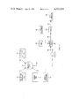
- FIG. 1 is a simplified diagrammatic illustration of apparatus for determining the octane number of a fuel in accordance with the present invention
- FIG. 2 is a simplified diagrammatic illustration of an embodiment of the invention which can be utilized where only a very small sample of the test fuel is available;
- FIG. 3 is a diagrammatic illustration of the preferred computer controlled apparatus configuration for determining the octane number of a fuel in accordance with the present invention.
- FIG. 4 is a flow chart illustrating the preferred method for determining the octane number of a fuel in accordance with the present invention.
- a warm-up fuel is provided from the supply 11 through conduit means 12 to the selector valve 13; a high octane reference fuel is provided from the supply 15 through conduit means 16 to the selector valve 13; a low octane reference fuel is provided from the supply 18 through conduit means 19 to the selector valve 13; and a test fuel is provided from the supply 21 through conduit means 22 to the selector valve 13.
- the supplies for the various fuels may be under pressure if desired or gravity flow may be utilized.
- a particular fuel is selected through use of the selector valve 13 and is provided through conduit means 24 to the pump 25.
- the fuel flowing through conduit means 24 is provided from the pump 25 through conduit means 28 to the engine 29.
- the pumping rate of the pump 25 is manipulated in such a manner that the fuel flowing through conduit means 28 flows at the mass flow rate which results in maximum knock.
- the mass flow rate of the fuel which gives maximum knock is substantially constant for a particular engine operating at a particular speed.
- the research octane number is determined in accordance with ASTM Method D-2699-79 by operating a standard ASTM-CFR engine at 600 RPM. Under these conditions the mass flow rate of each fuel which results in maximum knock is about 13 grams per minute. The required mass flow rate will vary with engine type and engine speed but once the mass flow rate that results in maximum knock for a particular engine operating at a particular speed is determined, this mass flow rate can be used for both the test fuel and the reference fuel.
- the volume flow rate of whatever fuel is flowing through conduit means 28 will be known. Any suitable method may be utilized to determine the actual mass flow rate based on the known volume flow rate. Preferably, the density measurement of whatever fuel is flowing through conduit means 24 by the density measuring device 31 is utilized to determine the actual mass flow rate.
- a suitable density measuring device is a Metler-Parr Density measuring device manufactured by Metler. The density of the fuel is multiplied by the volume flow rate to give the actual mass flow rate. Other techniques such as weighing a known volume of the fuel and multiplying the weight of the known volume of fuel by the volume flow rate can be utilized.
- the flow rate of the fuel flowing through conduit means 28 can be set directly to the mass flow rate which results in maximum knock by adjusting the volume flow rate until the desired mass flow rate is achieved.
- the successive approximation technique required by the ASTM methods is not required to find the flow rate of the fuel which will result in maximum knock.
- a pressure transducer associated with the engine 29 monitors the cylinder pressure in the engine 29 and produces a voltage signal 33 which is proportional to the rate of change of the cylinder pressure.
- Signal 33 is processed by the data processing equipment 35 to derive the knock intensity for the particular fuel being provided to the engine 29. Since the octane number of the high octane reference fuel and low octane reference fuel are known, and it is known that the engine is operating at conditions which give maximum knock for each of the fuels which are provided to the engine 29, the octane number of the test fuel can be derived directly by comparing the knock intensity of the test fuel to the knock intensity of the high octane reference fuel and the low octane reference fuel.
- Signal 33 may be processed by the standard ASTM methods which utilize a detonation meter and a knock meter or may be processed by other data processing techniques which may involve a computer as will be described hereinafter in conjunction with the description of FIG. 3.
- the warm-up fuel flowing from the supply 11 is utilized simply to warm up the engine 29 and may be utilized for any calibrations required.
- One of the reference fuels can be used for warm up purposes if desired.
- the high octane reference fuel, low octane reference fuel and test fuel are then provided sequentially to the engine 29.
- the high octane reference fuel, low octane reference fuel and test fuel may be provided to the engine 29 in any order but preferably the high octane reference fuel is provided to the engine 29, then the low octane reference fuel and then the test fuel.
- the two most generally used sets of reference fuels are 90/94 and 96/100.
- the 90/94 pair of reference fuels is preferably used to rate test fuels in the range of about 88 to about 95 octane and the 96/100 pair of reference fuels is preferably used to rate test fuels in the range of about 95 to about 100 octane.
- the high octane reference fuel and the low octane reference fuel should conform to the fuel requirements of ASTM Method D-2699-79 and D-2700-79 as outlined in sections 1, 3, 5, 6, and 8, and annexes 1-7 if the research octane number or motor octane number of a gasoline is being determined.
- selector valve 13 Any suitable apparatus for providing the different fuels sequentially to the pump 25 can be utilized.
- the use of the selector valve 13 is presently preferred but individual cutoff valves could be utilized with each of the fuel supplies being connected directly to the pump 25 if desired.
- a suitable selector valve 13 is a Whitey Selector valve, Model B-43ZF52.
- a suitable fuel pump 25 is a FMI Lab Pump Model RP-P-SSY-0. Since the FMI pump provides volumetric flow rate, it is necessary to convert the volumetric flow rate to a mass flow rate. As has been previously stated, this is preferably done utilizing a density measurement of the various fuels flowing through the pump 25 but can be accomplished by utilizing any suitable apparatus which results in the fuels flowing to the engine 29 at the same substantially constant mass flow rate.
- the engine 29 is preferably the ASTM-CFR engine which is required in the standard ASTM method for determining octane number.
- the ASTM-CFR engine is a one cylinder, four cycle engine which conforms to the requirements of ASTM Standard D-2699-79 and also includes a D-1 pressure transducer. Other engines may be required by other standard tests.
- FIG. 2 A variation of the present invention which results in the use of only a very small sample of the test fuel is illustrated in FIG. 2.
- Operation of the octane measuring system is essentially the same as that described in conjunction with FIG. 1 except for the use of the sample valve 42 which may be a model X valve manufactured by Applied Automation, Inc.
- Fuel flows from the pumping means 25 through conduit means 41 to the carrier fluid inlet of the sample valve 42 which is a well known device commonly utilized in chromatography.
- a test fuel is provided from the reservoir 46 through conduit means 43 to the sample inlet of the sample valve 42 to fill the sample loop of the sample valve 42.
- the fuel flowing through conduit means 41 is utilized as a carrier fluid.
- a measurement of the density of the test fuel in the reservoir 46 is provided by the density measuring device 45.
- the warm-up fuel, high octane reference fuel and low octane reference fuel are provided directly through the sample valve 42 to the engine 29 and the knock intensity for the high octane reference fuel and low octane reference fuel are determined as has been previously described.
- the pump 25 is first set to the flow rate which will provide maximum knock when the test fuel is flowing to the engine 29 based on the density measurement of the test fuel.
- the sample valve 42 is then switched such that the test fuel in the sample loop of the sample valve is provided to the engine 29 through conduit means 44.
- the fuel flowing through conduit means 41 acts as a carrier fluid and essentially a slug of test fuel is injected into the engine 29 with the carrier fluid preceding and following the slug.
- the knock intensity when the test fuel is flowing to the engine 29 is determined and the octane number of the test fuel is derived as has been previously described.
- FIG. 3 A preferred embodiment of the present invention in which the octane measuring system illustrated in FIG. 1 is under computer control is illustrated in FIG. 3.
- the engine 29 is preferably an ASTM-CFR engine as has been previously stated.
- the pump 25 is driven by a half-speed shaft 47 of the engine 29.
- a suitable shaft encoder 48 is a Disc Rotaswitch Shaft Encoder, Model X-701-360-T-C-L-TTL-SS manufactured by Disc Instruments.
- the shaft encoder 48 is operably connected to the half-speed shaft 47.
- the shaft encoder provides an output signal 51 which is a single transistor transistor logic (TTL) level pulse which is delivered once per engine cycle.
- Signal 51 is provided to the trigger input of the computer 50 and is utilized to provide timing information to the computer 50 which is preferably a Norland 3001 Processing Digital Oscilloscope manufactured by Norland Corporation.
- Signal 33 which is representative of the rate of change of the engine cylinder pressure as has been previously described, is provided to the channel 4 data input of the computer 50. Signal 33 is utilized to derive the octane number of the test fuel as will be described more fully hereinafter.
- the digital-to-analog converter outputs of the computer 50 are electrically connected to opposite poles of the potentiometer 61 (5KL).
- the wiper arm 62 of the potentiometer 61 is electrically connected to the non-inverting input of the operational amplifier 64 (Model 967 supplied by Analog Device Co.).
- the output signal 66 from the operational amplifier 64 is provided to the motor 67 which is associated with the pump setter 68 and is utilized to supply power to the motor 67.
- the drive shaft 69 of the motor 67 is utilized to set the pumping rate of the pump 25.
- the potentiometer 71 is utilized to provide feedback information concerning the pumping rate of the pump 25.
- the wiper arm 73 of the potentiometer 71 moves in response to the position of the shaft 69 to indicate the pump flow rate.
- the wiper arm 73 is electrically connected through the parallel combination of resistors 74 (100KL) and 75 (10KL) and capacitor 77 (0.33 mf) to the inverting input of the operational amplifier 64.
- a suitable pump setter 68 is a Motor Controlled Multi-turn Potentiometer No. 522-9505 distributed by Allied Electric. The manner in which the pump setter 68 and the circuitry associated with the pump setter 68 which interfaces the pump setter 68 to the computer 50 is utilized to manipulate the pumping rate of the pump 25 will be described more fully hereinafter.
- a +5 volt power supply 81 supplies power to the RLY-2 relay 82 associated with the computer 50.
- the relay 82 When the relay 82 is closed, power is supplied from the +5 volt power supply 81 to the relay 84.
- the relay 84 supplies power to the motor 85 which is associated with the valve driver 86.
- the shaft 88 associated with the motor 85 is utilized to manipulate the position of the selector valve 13.
- a suitable valve driver 86 is a Hoke Operator part No. 0112,L2P manufactured by Hoke.
- the switches 89 associated with the valve driver 86 provide information regarding the position of the shaft 88 to the computer 50.
- the switches 89 are electrically connected to the DIN 4-DIN 7 inputs of the computer 50. The manner in which the valve driver 86 in conjunction with the computer 50 is utilized to control the position of the selector valve 13 will be described more fully hereinafter.
- the digital-to-analog converter of the computer 50 establishes the pump flow rate required for the warm-up fuel to produce maximum knock from previously loaded density data.
- the high octane reference fuel, low octane reference fuel and warm-up fuel are chosen to have the same density; thus, the same flow setting provides maximum knock for each of these fuels.
- the engine 29 is then warmed up and the compression of the engine 29 is set based on the low octane reference fuel by the standard procedure set forth in ASTM 2699-79.
- the output of the digital-to-analog converter of the computer 50 determines the voltage applied to the non-inverting input of the operational amplifier 64.
- the operational amplifier 64 compares the signal supplied by the Norland digital-to-analog converter through the potentiometer 61 to the voltage which is provided from the potentiometer 71 to the inverting input of the operational amplifier 64.
- the voltage applied to the inverting input of the operational amplifier 64 is proportional to the pumping rate of pump 25.
- the difference between the values of the signals applied to the inverting and non-inverting inputs of the operational amplifier 64 determines the magnitude of the signal which is provided from the output of the operational amplifier 64 to the motor 67.
- the pumping rate of the pump 25 is changed by the output of the operational amplifier 64 until the signals applied to the inverting and non-inverting inputs of the operational amplifier 64 are balanced. In this manner, the pumping rate of the pump 25 is controlled directly from the computer 50 by the digital-to-analog converter output of the computer 50.
- the computer 50 is supplied with the density of the test fuel, the octane number of the high octane reference fuel and the octane number of the low octane reference fuel if different from the warm-up fuel.
- the computer is then allowed to run the high octane reference fuel, low octane reference fuel and test fuel through the engine 29. Data is acquired and the octane number of the test fuel is determined.
- the Norland computer 50 closes the relay 82 which supplies 5 volts to the relay 84.
- the relay 84 is turned on and power is supplied to the motor 85.
- the motor 85 rotates the selector valve 13 so that various fuel ports are connected singularly to the suction inlet of the pump 25.
- a cam on the drive shaft 88 energizes the switches 89 which are connected to the binary input lines of the Norland computer 50.
- the computer 50 automatically changes the position of the selector valve 13 as required to provide the different fuels to the engine 29.
- the pumping rate of the pump 25 is automatically set and adjusted to the pumping rate that provides a flow rate of fuel to the engine 29 resulting in a maximum knock condition for each particular fuel.
- Data acquisition by the computer 50 consists of utilizing the shaft encoder 48 to trigger the computer 50.
- 1,024 data points 20 microseconds apart are acquired.
- This array of data is 20.48 milliseconds in length and centered about the combustion part of the engine cycle. This procedure is repeated 128 times and the results are averaged.
- Similar data are acquired for the low octane reference fuel and the test fuel.
- the thus acquired data is then processed to remove the low frequency normal combustion portion of the data and leave the higher frequency portion of the trace that is due to knocking combustion.
- the area of each of the traces that is due to knocking is then measured and stored in a register in the computer 50.
- the thus stored areas are directly related to the knock intensity and over a range of several octane numbers a plot of knock intensity versus octane number is a straight line.
- the reference fuel knock intensities are used to construct a calibration equation which is utilized to calculate the octane number of the test fuel.
- the data acquired by the computer 50 is Fourier transformed after averaging. This converts the data to the frequency domain and provides an easy means for filtering the low frequency terms. An inverse Fourier transform is then performed on the filtered data and the area of each trace is determined as has been previously described. Many other techniques could be utilized to process the data.
- FIG. 4 A brief flow chart of the method of the present invention is illustrated in FIG. 4.
- the invention has been described with particular reference to the standard ASTM methods for determining the octane number of gasoline.
- the ASTM methods require the use of the ASTM-CFR engine. It is again noted that the present invention is applicable to any octane measurement using any suitable engine. Once the mass flow rate which results in maximum knock is determined for one fuel for a particular engine operating at a particular RPM, all the fuels required for the octane measurement are provided to the engine at that same mass flow rate with maximum knock resulting for all the fuels. This results in savings in time and fuel as has been previously stated.
Landscapes
- Chemical & Material Sciences (AREA)
- Health & Medical Sciences (AREA)
- Engineering & Computer Science (AREA)
- Life Sciences & Earth Sciences (AREA)
- Medicinal Chemistry (AREA)
- Biochemistry (AREA)
- General Chemical & Material Sciences (AREA)
- Food Science & Technology (AREA)
- Chemical Kinetics & Catalysis (AREA)
- Physics & Mathematics (AREA)
- Analytical Chemistry (AREA)
- Oil, Petroleum & Natural Gas (AREA)
- General Health & Medical Sciences (AREA)
- General Physics & Mathematics (AREA)
- Immunology (AREA)
- Pathology (AREA)
- Combined Controls Of Internal Combustion Engines (AREA)
- Electrical Control Of Air Or Fuel Supplied To Internal-Combustion Engine (AREA)
- Investigating Or Analysing Materials By Optical Means (AREA)
Priority Applications (8)
| Application Number | Priority Date | Filing Date | Title |
|---|---|---|---|
| US06/147,888 US4331024A (en) | 1980-05-08 | 1980-05-08 | Octane number measuring system |
| CA000376740A CA1163370A (en) | 1980-05-08 | 1981-05-01 | Octane number measuring system |
| DE8181103388T DE3173602D1 (en) | 1980-05-08 | 1981-05-05 | Apparatus and method for determining the octane number of test fuels |
| EP81103388A EP0039881B1 (en) | 1980-05-08 | 1981-05-05 | Apparatus and method for determining the octane number of test fuels |
| DK203881A DK203881A (da) | 1980-05-08 | 1981-05-07 | Anlaeg til maaling af octantallet |
| AU70234/81A AU545625B2 (en) | 1980-05-08 | 1981-05-07 | Determining octane ratings of fuels |
| JP6925581A JPS576359A (en) | 1980-05-08 | 1981-05-08 | Method of and apparatus for measuring fuel octane number |
| NO811564A NO811564L (no) | 1980-05-08 | 1981-05-08 | Fremgangsmaate og apparat til bestemmelse av oktantall |
Applications Claiming Priority (1)
| Application Number | Priority Date | Filing Date | Title |
|---|---|---|---|
| US06/147,888 US4331024A (en) | 1980-05-08 | 1980-05-08 | Octane number measuring system |
Publications (1)
| Publication Number | Publication Date |
|---|---|
| US4331024A true US4331024A (en) | 1982-05-25 |
Family
ID=22523338
Family Applications (1)
| Application Number | Title | Priority Date | Filing Date |
|---|---|---|---|
| US06/147,888 Expired - Lifetime US4331024A (en) | 1980-05-08 | 1980-05-08 | Octane number measuring system |
Country Status (8)
| Country | Link |
|---|---|
| US (1) | US4331024A (da) |
| EP (1) | EP0039881B1 (da) |
| JP (1) | JPS576359A (da) |
| AU (1) | AU545625B2 (da) |
| CA (1) | CA1163370A (da) |
| DE (1) | DE3173602D1 (da) |
| DK (1) | DK203881A (da) |
| NO (1) | NO811564L (da) |
Cited By (14)
| Publication number | Priority date | Publication date | Assignee | Title |
|---|---|---|---|---|
| US5457985A (en) * | 1993-02-01 | 1995-10-17 | Elf Antar France | Process for measuring the cetane number of supply fuels for diesel engines and apparatus for performing this process |
| US5633798A (en) * | 1995-04-13 | 1997-05-27 | Phillips Petroleum Company | Method and apparatus for measuring octane number |
| US6006587A (en) * | 1994-09-05 | 1999-12-28 | Aktsionernoe Obschestvo Zakrytogo Tipa Biotekhinvest | Method and device for determining the knock rating of motor fuels |
| US6155101A (en) * | 1996-04-15 | 2000-12-05 | Total Raffinage Distribution S.A. | Method and device for preparing a fuel, particularly for diesel engines, by on-line mixture of its components |
| US20090099754A1 (en) * | 2007-10-10 | 2009-04-16 | Audi Ag | Method and Device for Optimizing Combustion of Diesel Fuels with Different Cetane Numbers in a Diesel Internal Combustion Engine |
| US20110036147A1 (en) * | 2008-04-22 | 2011-02-17 | Rofa Laboratory & Process Analyzers | Method for characterising the knock-resistance of fuels |
| US8628594B1 (en) | 2009-12-01 | 2014-01-14 | George W. Braly | High octane unleaded aviation fuel |
| WO2015061581A1 (en) * | 2013-10-25 | 2015-04-30 | Michaelis Chad Alan | Determining the knock rating of liquid spark-ignition engine fuels |
| US10260016B2 (en) | 2009-12-01 | 2019-04-16 | George W. Braly | High octane unleaded aviation gasoline |
| US10364399B2 (en) | 2017-08-28 | 2019-07-30 | General Aviation Modifications, Inc. | High octane unleaded aviation fuel |
| US10377959B2 (en) | 2017-08-28 | 2019-08-13 | General Aviation Modifications, Inc. | High octane unleaded aviation fuel |
| US10550347B2 (en) | 2009-12-01 | 2020-02-04 | General Aviation Modifications, Inc. | High octane unleaded aviation gasoline |
| CN112627929A (zh) * | 2020-12-30 | 2021-04-09 | 上海神开石油仪器有限公司 | 一种汽油辛烷值测定机预热方法和装置 |
| US20220220915A1 (en) * | 2020-02-05 | 2022-07-14 | ExxonMobil Technology and Engineering Company | Method of assigning an octane number to a fuel |
Families Citing this family (4)
| Publication number | Priority date | Publication date | Assignee | Title |
|---|---|---|---|---|
| FR2611911B1 (fr) * | 1987-02-27 | 1989-06-23 | Bp France | Procede de determination directe d'un indice d'octane |
| DE202015000544U1 (de) | 2015-01-27 | 2015-06-19 | Asg Analytik-Service Gesellschaft Mbh | Apparatur zur automatisierten Oktanzahlbestimmung von Ottokraftstoffen |
| EP3051289A1 (de) | 2015-01-27 | 2016-08-03 | ASG Analytik-Service Gesellschaft mbH | Apparatur und Verfahren zur automatisierten Oktanzahlbestimmung von Ottokraftstoffen |
| US20260002486A1 (en) * | 2024-06-28 | 2026-01-01 | Cfr Engines Inc. | Systems and methods for octane number rating with electronic fuel injection |
Citations (7)
| Publication number | Priority date | Publication date | Assignee | Title |
|---|---|---|---|---|
| US2936609A (en) * | 1957-11-20 | 1960-05-17 | Waukesha Motor Co | Art of knock-rating gasolines under supercharged operating conditions |
| US3183708A (en) * | 1961-10-12 | 1965-05-18 | Shell Oil Co | Method and apparatus for metering pressure phenomena in internal combustion engines |
| US3318136A (en) * | 1964-06-09 | 1967-05-09 | Mobil Oil Corp | Method and apparatus for testing fuels |
| US3469954A (en) * | 1964-11-10 | 1969-09-30 | Du Pont | Apparatus for controlling octane value in gasoline |
| US3503722A (en) * | 1968-08-13 | 1970-03-31 | Mobil Oil Corp | Blending system |
| US3969922A (en) * | 1975-06-19 | 1976-07-20 | E. I. Du Pont De Nemours And Company | Apparatus for feeding fuel to an engine |
| US4010358A (en) * | 1975-06-19 | 1977-03-01 | E. I. Du Pont De Nemours And Company | Apparatus and process for measuring fuel octane numbers |
-
1980
- 1980-05-08 US US06/147,888 patent/US4331024A/en not_active Expired - Lifetime
-
1981
- 1981-05-01 CA CA000376740A patent/CA1163370A/en not_active Expired
- 1981-05-05 EP EP81103388A patent/EP0039881B1/en not_active Expired
- 1981-05-05 DE DE8181103388T patent/DE3173602D1/de not_active Expired
- 1981-05-07 AU AU70234/81A patent/AU545625B2/en not_active Ceased
- 1981-05-07 DK DK203881A patent/DK203881A/da not_active Application Discontinuation
- 1981-05-08 NO NO811564A patent/NO811564L/no unknown
- 1981-05-08 JP JP6925581A patent/JPS576359A/ja active Pending
Patent Citations (7)
| Publication number | Priority date | Publication date | Assignee | Title |
|---|---|---|---|---|
| US2936609A (en) * | 1957-11-20 | 1960-05-17 | Waukesha Motor Co | Art of knock-rating gasolines under supercharged operating conditions |
| US3183708A (en) * | 1961-10-12 | 1965-05-18 | Shell Oil Co | Method and apparatus for metering pressure phenomena in internal combustion engines |
| US3318136A (en) * | 1964-06-09 | 1967-05-09 | Mobil Oil Corp | Method and apparatus for testing fuels |
| US3469954A (en) * | 1964-11-10 | 1969-09-30 | Du Pont | Apparatus for controlling octane value in gasoline |
| US3503722A (en) * | 1968-08-13 | 1970-03-31 | Mobil Oil Corp | Blending system |
| US3969922A (en) * | 1975-06-19 | 1976-07-20 | E. I. Du Pont De Nemours And Company | Apparatus for feeding fuel to an engine |
| US4010358A (en) * | 1975-06-19 | 1977-03-01 | E. I. Du Pont De Nemours And Company | Apparatus and process for measuring fuel octane numbers |
Non-Patent Citations (1)
| Title |
|---|
| "Mercedes-Benz 280E", Car and Driver Magazine, pp. 62-68, 3/77. |
Cited By (24)
| Publication number | Priority date | Publication date | Assignee | Title |
|---|---|---|---|---|
| US5457985A (en) * | 1993-02-01 | 1995-10-17 | Elf Antar France | Process for measuring the cetane number of supply fuels for diesel engines and apparatus for performing this process |
| US6006587A (en) * | 1994-09-05 | 1999-12-28 | Aktsionernoe Obschestvo Zakrytogo Tipa Biotekhinvest | Method and device for determining the knock rating of motor fuels |
| US5633798A (en) * | 1995-04-13 | 1997-05-27 | Phillips Petroleum Company | Method and apparatus for measuring octane number |
| AU685358B2 (en) * | 1995-04-13 | 1998-01-15 | Phillips Petroleum Company | Method and apparatus for determining the octane number of a testfuel |
| EP0737862A3 (en) * | 1995-04-13 | 1998-08-19 | Phillips Petroleum Company | Method and apparatus for measuring octane number |
| US6155101A (en) * | 1996-04-15 | 2000-12-05 | Total Raffinage Distribution S.A. | Method and device for preparing a fuel, particularly for diesel engines, by on-line mixture of its components |
| US20090099754A1 (en) * | 2007-10-10 | 2009-04-16 | Audi Ag | Method and Device for Optimizing Combustion of Diesel Fuels with Different Cetane Numbers in a Diesel Internal Combustion Engine |
| US8402939B2 (en) * | 2007-10-10 | 2013-03-26 | Audi Ag | Method and device for optimizing combustion of diesel fuels with different cetane numbers in a diesel internal combustion engine |
| US20110036147A1 (en) * | 2008-04-22 | 2011-02-17 | Rofa Laboratory & Process Analyzers | Method for characterising the knock-resistance of fuels |
| US8468873B2 (en) | 2008-04-22 | 2013-06-25 | Rofa Laboratory & Process Analyzers | Method for characterising the knock-resistance of fuels |
| US11098259B2 (en) | 2009-12-01 | 2021-08-24 | General Aviation Modifications, Inc. | High octane unleaded aviation gasoline |
| US11674100B2 (en) | 2009-12-01 | 2023-06-13 | General Aviation Modifications, Inc. | High octane unleaded aviation gasoline |
| US10260016B2 (en) | 2009-12-01 | 2019-04-16 | George W. Braly | High octane unleaded aviation gasoline |
| US12305135B2 (en) | 2009-12-01 | 2025-05-20 | General Aviation Modifications, Inc. | High octane unleaded aviation gasoline |
| US10550347B2 (en) | 2009-12-01 | 2020-02-04 | General Aviation Modifications, Inc. | High octane unleaded aviation gasoline |
| US12157864B2 (en) | 2009-12-01 | 2024-12-03 | General Aviation Modifications, Inc. | Unleaded avgas composition |
| US8628594B1 (en) | 2009-12-01 | 2014-01-14 | George W. Braly | High octane unleaded aviation fuel |
| US9823233B2 (en) | 2013-10-25 | 2017-11-21 | Chad Alan Michaelis | Determining the knock rating of liquid spark-ignition engine fuels |
| WO2015061581A1 (en) * | 2013-10-25 | 2015-04-30 | Michaelis Chad Alan | Determining the knock rating of liquid spark-ignition engine fuels |
| US10364399B2 (en) | 2017-08-28 | 2019-07-30 | General Aviation Modifications, Inc. | High octane unleaded aviation fuel |
| US10377959B2 (en) | 2017-08-28 | 2019-08-13 | General Aviation Modifications, Inc. | High octane unleaded aviation fuel |
| US20220220915A1 (en) * | 2020-02-05 | 2022-07-14 | ExxonMobil Technology and Engineering Company | Method of assigning an octane number to a fuel |
| US11821381B2 (en) * | 2020-02-05 | 2023-11-21 | ExxonMobil Technology and Engineering Company | Method of assigning an octane number to a fuel |
| CN112627929A (zh) * | 2020-12-30 | 2021-04-09 | 上海神开石油仪器有限公司 | 一种汽油辛烷值测定机预热方法和装置 |
Also Published As
| Publication number | Publication date |
|---|---|
| NO811564L (no) | 1981-11-09 |
| DE3173602D1 (en) | 1986-03-13 |
| JPS576359A (en) | 1982-01-13 |
| AU7023481A (en) | 1981-11-12 |
| AU545625B2 (en) | 1985-07-25 |
| EP0039881A3 (en) | 1982-08-25 |
| EP0039881B1 (en) | 1986-01-29 |
| CA1163370A (en) | 1984-03-06 |
| EP0039881A2 (en) | 1981-11-18 |
| DK203881A (da) | 1981-11-09 |
Similar Documents
| Publication | Publication Date | Title |
|---|---|---|
| US4402212A (en) | Octane number measuring system | |
| US4331024A (en) | Octane number measuring system | |
| US5457985A (en) | Process for measuring the cetane number of supply fuels for diesel engines and apparatus for performing this process | |
| US4129034A (en) | Method and apparatus for checking engine performance | |
| US5633798A (en) | Method and apparatus for measuring octane number | |
| EP0165402B1 (en) | Method of measuring leak rates | |
| US5641891A (en) | Method for setting and checking the flow in valves | |
| JPH07286541A (ja) | 燃料管路圧力調整器機能不全検出用車上診断装置を有する内燃機関 | |
| JPH03179257A (ja) | 液体クロマトグラフィ用装置及び方法 | |
| GB2089441A (en) | A method of determining the start of the delivery in injection pumps | |
| CN101004161A (zh) | 发动机共轨用电控高压油泵性能试验装置和试验方法 | |
| EP1114244A1 (de) | Vorrichtung zur erfassung einer pulsierenden grösse | |
| JPS5872673A (ja) | 内燃機関の噴射ポンプからの燃料噴射量の測定装置 | |
| US4879662A (en) | Fluid flow self calibration scheme | |
| EP0611962B1 (en) | Method and apparatus for extracting particulate from the exhaust gases of diesel engines | |
| US6155101A (en) | Method and device for preparing a fuel, particularly for diesel engines, by on-line mixture of its components | |
| US20040154384A1 (en) | Method and apparatus for defining water content of a liquid | |
| GB1514443A (en) | Automatic analytical measurements | |
| Capobianco et al. | Effect of inlet pulsating pressure characteristics on turbine performance of an automotive wastegated turbocharger | |
| RU2648175C1 (ru) | Устройство для испытания топливных насосов высокого давления | |
| SU1513196A1 (ru) | Способ диагностировани технического состо ни насоса | |
| US3511980A (en) | Delta road octane computer for controlling the octane quality of a gasoline blend | |
| Godburn et al. | Computer–controlled non–steady–state engine testing | |
| IZVOREAN et al. | LOW-COST HIGH PRECISION FUEL CONSUMTION MEASUREMENT SISTEM | |
| SU1000855A1 (ru) | Устройство автоматического измерени параметров водонефт ных эмульсий |
Legal Events
| Date | Code | Title | Description |
|---|---|---|---|
| STCF | Information on status: patent grant |
Free format text: PATENTED CASE |