US4302955A - Bicycle lock - Google Patents
Bicycle lock Download PDFInfo
- Publication number
- US4302955A US4302955A US06/111,334 US11133480A US4302955A US 4302955 A US4302955 A US 4302955A US 11133480 A US11133480 A US 11133480A US 4302955 A US4302955 A US 4302955A
- Authority
- US
- United States
- Prior art keywords
- pair
- knob
- casing
- shaft
- wheel
- Prior art date
- Legal status (The legal status is an assumption and is not a legal conclusion. Google has not performed a legal analysis and makes no representation as to the accuracy of the status listed.)
- Expired - Lifetime
Links
- 230000002093 peripheral effect Effects 0.000 claims abstract description 6
- 229910000831 Steel Inorganic materials 0.000 abstract description 4
- 239000010959 steel Substances 0.000 abstract description 4
- 238000010276 construction Methods 0.000 description 1
- 238000005192 partition Methods 0.000 description 1
Images

Classifications
-
- E—FIXED CONSTRUCTIONS
- E05—LOCKS; KEYS; WINDOW OR DOOR FITTINGS; SAFES
- E05B—LOCKS; ACCESSORIES THEREFOR; HANDCUFFS
- E05B67/00—Padlocks; Details thereof
- E05B67/003—Chain, wire or cable locks
-
- E—FIXED CONSTRUCTIONS
- E05—LOCKS; KEYS; WINDOW OR DOOR FITTINGS; SAFES
- E05B—LOCKS; ACCESSORIES THEREFOR; HANDCUFFS
- E05B37/00—Permutation or combination locks; Puzzle locks
- E05B37/08—Permutation or combination locks; Puzzle locks with tumbler discs on a single axis, all the discs being adjustable by a rotary knob which is not shifted for adjusting the discs
-
- Y—GENERAL TAGGING OF NEW TECHNOLOGICAL DEVELOPMENTS; GENERAL TAGGING OF CROSS-SECTIONAL TECHNOLOGIES SPANNING OVER SEVERAL SECTIONS OF THE IPC; TECHNICAL SUBJECTS COVERED BY FORMER USPC CROSS-REFERENCE ART COLLECTIONS [XRACs] AND DIGESTS
- Y10—TECHNICAL SUBJECTS COVERED BY FORMER USPC
- Y10T—TECHNICAL SUBJECTS COVERED BY FORMER US CLASSIFICATION
- Y10T70/00—Locks
- Y10T70/40—Portable
- Y10T70/413—Padlocks
- Y10T70/417—Combination-controlled
- Y10T70/435—Flexible shackle
-
- Y—GENERAL TAGGING OF NEW TECHNOLOGICAL DEVELOPMENTS; GENERAL TAGGING OF CROSS-SECTIONAL TECHNOLOGIES SPANNING OVER SEVERAL SECTIONS OF THE IPC; TECHNICAL SUBJECTS COVERED BY FORMER USPC CROSS-REFERENCE ART COLLECTIONS [XRACs] AND DIGESTS
- Y10—TECHNICAL SUBJECTS COVERED BY FORMER USPC
- Y10T—TECHNICAL SUBJECTS COVERED BY FORMER US CLASSIFICATION
- Y10T70/00—Locks
- Y10T70/70—Operating mechanism
- Y10T70/7153—Combination
- Y10T70/7181—Tumbler type
- Y10T70/7198—Single tumbler set
- Y10T70/7237—Rotary or swinging tumblers
- Y10T70/7243—Interset tumblers
- Y10T70/7249—Tumblers released
Definitions
- This invention relates to a bicycle lock consisting of a combination lock and a length of steel cable or chain connected with the ends of said lock.
- the combination lock employed herein is novel in its construction.
- a shaft is unrotatively arranged within the casing of the lock. Adjacent to one end of the shaft, a knob is rotatably mounted. Between the knob and the shaft, a well known click mechanism consisting of a ball and a spring is placed.
- step wheels each having a recess in its periphery, are loosely mounted on the shaft.
- a retaining wheel Adjacent to the first step wheel which is farthest from the knob, a retaining wheel having a recess in its periphery, is loosely mounted on the shaft and is rotatable with the first step wheel.
- a retainer of an inverted "C" form is mounted slidably across the shaft. The retainer is provided with laterally extended ends. The outer end of thereof juts from the casing.
- the lock bolt inserted in the casing is provided with three notches each corresponding to one of the step wheels. In the locking position, all the step wheels engage with notches and the inner end of the retainer engages with the recess provided in the periphery of the retaining wheel so that the knob can rotate no more and the outer end of the retainer projects fully from the casing.
- the knob is first turned clockwise until the number of click sounds coinciding the first numeral of the code number are heard, whereby the first step wheel which is farthest from the knob is brought to the release position wherein its peripheral recess lies just above the corresponding notch of the locking bolt.
- the knob is turned counter-clockwise until click sounds coinciding with the second numeral of the code number are heard whereby the second step wheel is brought to the release position wherein its peripheral recess lies just above the corresponding notch of the locking bolt.
- the knob is turned again clockwise until click sounds coinciding with the final numeral of the code number are heard whereby the third step wheel adjacent to the knob is brought to the release position wherein its peripheral recess lies just above the corresponding notch of the bolt.
- the bolt may be withdrawn from the casing.
- FIG. 1 is a perspective view of the bicycle lock of the present invention
- FIG. 2 is a longitudinal sectional view thereof in the locked state
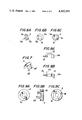
- FIG. 3A is a side view of the retaining wheel
- FIG. 3B is a front view of the retaining wheel
- FIG. 4A is a side view of the first step wheel
- FIG. 4B is a front view of the first step wheel
- FIG. 4C is a rear view of the first step wheel
- FIG. 5A is a side view of the second step wheel
- FIG. 5B is a front view of the second step wheel
- FIG. 5C is a rear view of the second step wheel
- FIG. 6A is a side view of the third step wheel
- FIG. 6B is a front view of the third step wheel.
- FIG. 6C is a rear view of the third step wheel
- FIG. 7 illustrates a double clip
- FIG. 8A is a side view of the retainer
- FIG. 8B is a plan view of the retainer
- FIG. 9A is a front view of the knob
- FIG. 9B is a side view of the knob.
- FIG. 9C is a rear view of the knob.
- the lock of the invention comprises a tubular casing 9 having an end provided with a rotatable knob 2, while the other end of the casing is provided with a detachable cap 10.
- the knob is rotatably mounted on one end of the shaft 1 which is unrotatably supported in the casing 9.
- a ball 16 and a spring 17 arranged between the knob 2 and the shaft 1 constitute a well known click mechanism to assure each rotating position of the knob 2.
- step wheels On the shaft 1, three step wheels, namely first step wheel 3a, second step wheel 4a and third step wheel 5a are loosely mounted. Each step wheel is provided with a recess in its periphery.
- the first step wheel 3a as shown in FIGS. 4A-4C, which is farthest from the knob 2 is provided with a recess 6 at its periphery and its flange member 3 is provided with a projection 3c. Further, its front is provided with five recesses 3b.
- the second step wheel 4a as shown in FIGS. 5A-5C is provided with a recess 7 in its periphery and its flange member 4 as well as one side of the step wheel are provided with projections 4c and 4d respectively.
- the third step wheel 5a as shown in FIGS. 6A-6C, which is adjacent to the knob 2, is provided with a recess 8 in its periphery, and its flange member 5 and one side of the step wheel is provided with projections 5c and 5d respectively.
- the retaining wheel 19, as shown in FIGS. 3A-3B, is loosely or slidably mounted on the shaft 1 adjacent to the first step wheel 3a.
- the retaining wheel 19 is provided with a recess 21 in its periphery and a projection 2a at one side.
- the projection 2a is inserted into either one of the five recesses 3b of the first step wheel 3a so as to obtain five different code numbers without changing any of the step wheels.
- the knob 2 as shown in FIGS. 9A-9C, is provided with a projection 2a at one side and six recesses 18 arranged circularly at the other side.
- the movement of the knob 2 is transmitted to the third step wheel 4a through the engagement of the projection 2a of the knob 2 and the projection 5c of the third step wheel 5a.
- the movement of the third step wheel 5a is transmitted to the second step wheel 4a through the engagement of the projection 5d of the third step wheel 5a and the projection 4c of the second step wheel 4a.
- the movement of the second step wheel 4a is transmitted to the first step wheel 3a and the retaining wheel 19 through the engagement of the projection 4d of the second step wheel 4a and the projection 3c of the first step wheel 3a.
- a retainer 12 of an inverted "C" form Adjacent to the retaining wheel, 19 a retainer 12 of an inverted "C" form, as shown in FIGS. 8A-8B, is slidably placed across the shaft 1 between partition walls 22 and 23.
- the retainer 12 is provided with laterally extended end portions 12a and 12b.
- the outer end portion 12b partially juts from the casing 9 as shown in FIG. 1.
- the retainer 12 tends to slide outward by the action of a spring 13.
- the inner end portion 12a engages with the recess 21 of the retaining wheel 19 at the locked state of the lock.
- a double clip as shown in FIG. 7, is employed to prevent unwanted movements of the first and the second step wheels 3a and 4a respectively.
- the double clip is composed of two clip members 14' and 14". The joint of the double clip is inserted in a longitudinal groove formed in the inner surface of the casing 9.
- the clip members 14' and 14 resiliently and frictionally engage with the flange members 3 and 4 respectively of the first and the second step wheels 3a and 4a respectively.
- the cap 10 is secured to, or integral with, one end of a bolt 11. As shown in FIG. 2, the bolt 11 is provided with three notches 11a, 11b and 11c which engage with portions of the peripheries of the step wheels 3a, 4a and 5a, respectively, in the locking position.
- a length of steel cable or chain 15 is connected to connecting members 1' and 10' whereby the cable or chain and the lock form a loop when said lock is in the locked position.
- the connecting members 1' and 10' are formed on one body with the shaft 1 and cap 10, respectively.
- the knob 2 is turned in a counter-clockwise direction until six click sounds are heard whereby the movement of the knob 2 is transmitted to the second step wheel 4a through the cooperation of the projections 2a, 5c, 5d and 4c so as to bring the second step wheel 4a to the position wherein its recess 7 lies just above the notch 11b provided on the bolt 11.
- the knob 2 is turned in a clockwise direction again until four click sounds are heard whereby the movement of the knob 2 is transmitted to the third step wheel 5a through the engagement of the projections 2a and 5c and the third step wheel 5a is brought to the position wherein its recess 8 lies just above the notch 11c provided on the bolt 11.
- all the recesses provided in the peripheries of three step wheels are brought one by one above the corresponding notches of the bolt 11, whereby the bolt is released from the grips of the step wheels and may be withdrawn from the casing 9.
- the bolt 11 is inserted in the casing 9 and the knob 2 is turned clockwise until the end portion 12b projects fully from the casing 9 so as immobilize the knob 2.
- the bicycle lock of this invention can be unlocked by turning the knob 2 first in one direction, next in an opposite direction and finally in the same direction as the first and simultaneously listening number of click sounds coinciding with the code number.
- this lock can be unlocked in the dark.
Landscapes
- Mechanical Control Devices (AREA)
Abstract
A combination lock and a length of steel cable of chain connected with the ends of said lock is disclosed. The lock comprises a bolt inserted in a casing having a shaft unrotatably disposed therein. Adjacent to one end of the shaft, a knob is mounted. Three step wheels, each having a peripheral recess, are also loosely mounted on the shaft. The step wheels are provided with a projection or projections on one or both sides for transmitting the movements of the knob. Adjacent to the first step wheel which is farthest from the knob, a retaining wheel is mounted on the shaft. The retaining wheel is provided with a recess at its periphery and a projection at one side. The projection is inserted in either one of five recesses provided at one side of the first step wheel whereby five different code numbers will be obtained without changing the step wheels. A click mechanism is arranged between the shaft and the knob. Adjacent to the retaining wheel, a retainer of an inverted "C" form having laterally extending end portions is slidably mounted across the shaft. In the locked state, the inner end portion of the retainer engages with the recess of the retaining wheel while the outer end portion protrudes from the casing by the action of a spring whereby the knob can not be turned. This lock has no numeral indicating means and is unlocked by listening to clicking sounds.
Description
This invention relates to a bicycle lock consisting of a combination lock and a length of steel cable or chain connected with the ends of said lock.
The combination lock employed herein is novel in its construction. A shaft is unrotatively arranged within the casing of the lock. Adjacent to one end of the shaft, a knob is rotatably mounted. Between the knob and the shaft, a well known click mechanism consisting of a ball and a spring is placed.
Three step wheels, each having a recess in its periphery, are loosely mounted on the shaft. Adjacent to the first step wheel which is farthest from the knob, a retaining wheel having a recess in its periphery, is loosely mounted on the shaft and is rotatable with the first step wheel. Further, adjacent to said retaining wheel, a retainer of an inverted "C" form is mounted slidably across the shaft. The retainer is provided with laterally extended ends. The outer end of thereof juts from the casing.
The lock bolt inserted in the casing is provided with three notches each corresponding to one of the step wheels. In the locking position, all the step wheels engage with notches and the inner end of the retainer engages with the recess provided in the periphery of the retaining wheel so that the knob can rotate no more and the outer end of the retainer projects fully from the casing.
To unlock, one must first push the outer end of the retainer projecting from the casing inward so as to release the retaining wheel, then the knob is first turned clockwise until the number of click sounds coinciding the first numeral of the code number are heard, whereby the first step wheel which is farthest from the knob is brought to the release position wherein its peripheral recess lies just above the corresponding notch of the locking bolt. Next, the knob is turned counter-clockwise until click sounds coinciding with the second numeral of the code number are heard whereby the second step wheel is brought to the release position wherein its peripheral recess lies just above the corresponding notch of the locking bolt. Finally the knob is turned again clockwise until click sounds coinciding with the final numeral of the code number are heard whereby the third step wheel adjacent to the knob is brought to the release position wherein its peripheral recess lies just above the corresponding notch of the bolt. The as all step wheels disengage from the notches of the bolt, the bolt may be withdrawn from the casing.
As is clear from the above, numerals of the code number are indicated by number of click sounds, the lock of this invention can be unlocked in the dark by listening click sounds.
The diverse purposes and advantages of the invention and a better understanding thereof may be had by reference to the following description, taken in conjunction with the accompanying drawing, in which:
FIG. 1 is a perspective view of the bicycle lock of the present invention;
FIG. 2 is a longitudinal sectional view thereof in the locked state;
FIG. 3A is a side view of the retaining wheel; and
FIG. 3B is a front view of the retaining wheel;
FIG. 4A is a side view of the first step wheel;
FIG. 4B is a front view of the first step wheel; and
FIG. 4C is a rear view of the first step wheel;
FIG. 5A is a side view of the second step wheel;
FIG. 5B is a front view of the second step wheel; and
FIG. 5C is a rear view of the second step wheel;
FIG. 6A is a side view of the third step wheel;
FIG. 6B is a front view of the third step wheel; and
FIG. 6C is a rear view of the third step wheel;
FIG. 7 illustrates a double clip;
FIG. 8A is a side view of the retainer; and
FIG. 8B is a plan view of the retainer; and
FIG. 9A is a front view of the knob;
FIG. 9B is a side view of the knob; and
FIG. 9C is a rear view of the knob.
As illustrated in the drawings, and more particularly at FIGS. 1 and 2, the lock of the invention comprises a tubular casing 9 having an end provided with a rotatable knob 2, while the other end of the casing is provided with a detachable cap 10. The knob is rotatably mounted on one end of the shaft 1 which is unrotatably supported in the casing 9. A ball 16 and a spring 17 arranged between the knob 2 and the shaft 1 constitute a well known click mechanism to assure each rotating position of the knob 2.
On the shaft 1, three step wheels, namely first step wheel 3a, second step wheel 4a and third step wheel 5a are loosely mounted. Each step wheel is provided with a recess in its periphery.
The first step wheel 3a, as shown in FIGS. 4A-4C, which is farthest from the knob 2 is provided with a recess 6 at its periphery and its flange member 3 is provided with a projection 3c. Further, its front is provided with five recesses 3b. The second step wheel 4a, as shown in FIGS. 5A-5C is provided with a recess 7 in its periphery and its flange member 4 as well as one side of the step wheel are provided with projections 4c and 4d respectively. The third step wheel 5a, as shown in FIGS. 6A-6C, which is adjacent to the knob 2, is provided with a recess 8 in its periphery, and its flange member 5 and one side of the step wheel is provided with projections 5c and 5d respectively.
The retaining wheel 19, as shown in FIGS. 3A-3B, is loosely or slidably mounted on the shaft 1 adjacent to the first step wheel 3a. The retaining wheel 19 is provided with a recess 21 in its periphery and a projection 2a at one side. The projection 2a is inserted into either one of the five recesses 3b of the first step wheel 3a so as to obtain five different code numbers without changing any of the step wheels.
The knob 2, as shown in FIGS. 9A-9C, is provided with a projection 2a at one side and six recesses 18 arranged circularly at the other side.
The movement of the knob 2 is transmitted to the third step wheel 4a through the engagement of the projection 2a of the knob 2 and the projection 5c of the third step wheel 5a. The movement of the third step wheel 5a is transmitted to the second step wheel 4a through the engagement of the projection 5d of the third step wheel 5a and the projection 4c of the second step wheel 4a. The movement of the second step wheel 4a is transmitted to the first step wheel 3a and the retaining wheel 19 through the engagement of the projection 4d of the second step wheel 4a and the projection 3c of the first step wheel 3a.
Adjacent to the retaining wheel, 19 a retainer 12 of an inverted "C" form, as shown in FIGS. 8A-8B, is slidably placed across the shaft 1 between partition walls 22 and 23. The retainer 12 is provided with laterally extended end portions 12a and 12b. The outer end portion 12b partially juts from the casing 9 as shown in FIG. 1. The retainer 12 tends to slide outward by the action of a spring 13. The inner end portion 12a engages with the recess 21 of the retaining wheel 19 at the locked state of the lock.
A double clip, as shown in FIG. 7, is employed to prevent unwanted movements of the first and the second step wheels 3a and 4a respectively. The double clip is composed of two clip members 14' and 14". The joint of the double clip is inserted in a longitudinal groove formed in the inner surface of the casing 9. The clip members 14' and 14", resiliently and frictionally engage with the flange members 3 and 4 respectively of the first and the second step wheels 3a and 4a respectively.
The cap 10 is secured to, or integral with, one end of a bolt 11. As shown in FIG. 2, the bolt 11 is provided with three notches 11a, 11b and 11c which engage with portions of the peripheries of the step wheels 3a, 4a and 5a, respectively, in the locking position.
A length of steel cable or chain 15 is connected to connecting members 1' and 10' whereby the cable or chain and the lock form a loop when said lock is in the locked position. The connecting members 1' and 10' are formed on one body with the shaft 1 and cap 10, respectively.
The operation of the bicycle lock may now be described, assuming the code number is [2]-[6]-[4], for example.
For unlocking, first push the end portion 12b which is projecting from the casing 9 inward with a finger against the action of the spring 13 so as to release the retaining wheel 19 by disengaging the end portion 12a from the recess 21 of the retaining wheel 19. Then, the knob 2 is turned in a clockwise direction until two click sounds are heard. Pushing on the end portion 12b is no longer necessary. The movement of the knob 2 is transmitted to the first step wheel 3a and the retaining wheel 19 through the engagement on the projections 2a and 5c, 5d and 4c, and 4d and 3c in succession and the first step wheel 3a is brought to the position wherein its recess 6 is located just above the notch 11a provided in the bolt 11.
Next, the knob 2 is turned in a counter-clockwise direction until six click sounds are heard whereby the movement of the knob 2 is transmitted to the second step wheel 4a through the cooperation of the projections 2a, 5c, 5d and 4c so as to bring the second step wheel 4a to the position wherein its recess 7 lies just above the notch 11b provided on the bolt 11.
Finally, the knob 2 is turned in a clockwise direction again until four click sounds are heard whereby the movement of the knob 2 is transmitted to the third step wheel 5a through the engagement of the projections 2a and 5c and the third step wheel 5a is brought to the position wherein its recess 8 lies just above the notch 11c provided on the bolt 11. Thus, all the recesses provided in the peripheries of three step wheels are brought one by one above the corresponding notches of the bolt 11, whereby the bolt is released from the grips of the step wheels and may be withdrawn from the casing 9.
In order to lock the device, after the steel cable or chain 15 is led around the rim of the front wheel and the front fork of a bicycle, and a post or the like, the bolt 11 is inserted in the casing 9 and the knob 2 is turned clockwise until the end portion 12b projects fully from the casing 9 so as immobilize the knob 2.
As is clear from the above description, the bicycle lock of this invention can be unlocked by turning the knob 2 first in one direction, next in an opposite direction and finally in the same direction as the first and simultaneously listening number of click sounds coinciding with the code number. Thus, this lock can be unlocked in the dark.
Although the present invention has been described as consisting of three step wheels, thereby providing a code number consisting of three digits, it will be readily apparent that only two step wheels could be used, thus providing for a two-digit code number, or more than three step wheels could be used, thus providing for a multi-digit code number.
Claims (1)
1. A bicycle lock comprising:
a casing having a hole;
a retainer mounted adjacent said casing, said retainer having a one end portion projecting into said hole of said casing;
a shaft unrotatably supported in said hole of said casing;
a knob slidably mounted adjacent to the one end of said shaft;
at least one pair of step wheels slidably mounted on said shaft, each of said at least one pair of step wheels having a recess in its periphery, a reduced diameter cylindrical lateral flange adjacent said recess in its periphery, and a plurality of axial recesses formed in the face of said reduced diameter cylindrical lateral flange;
a retaining wheel slidably mounted on said shaft, said retaining wheel having a projection on one side engaging at least one of said plurality of axial recesses in one of said at least one pair of step wheels;
a clip disposed within said casing for preventing accidental movements of said at least one pair of step wheels, said clip having at least one clip member in frictional peripheral engagement with said lateral flange of the other of said at least one pair of step wheels;
a retainer slidably mounted adjacent to said retaining wheel, said retainer having a pair of laterally extending end portions, one of said pair of laterally extending end portions further engaging at least one of said plurality of axial recesses in said retaining wheel while the other of said pair of laterally extending end portions further projects outward from said hole in said casing;
a locking bolt inserted in said casing, said locking bolt having a plurality of notches corresponding with said peripheral recesses in said at least one pair of step wheels and a cap at one end;
a length of chain having one end connected to said cap and an opposite end connected to said knob; and
means for transmitting the rotation of said knob to each of said pair of step wheels, said transmitting means further comprising:
a laterial projection on at least one side of each of said pair of step wheels, each of said lateral projections on one of said step wheels further being engageable with said lateral projection on one side of the other of said pair of step wheels.
Priority Applications (1)
| Application Number | Priority Date | Filing Date | Title |
|---|---|---|---|
| US06/111,334 US4302955A (en) | 1979-04-04 | 1980-01-11 | Bicycle lock |
Applications Claiming Priority (2)
| Application Number | Priority Date | Filing Date | Title |
|---|---|---|---|
| JP54-39686 | 1979-04-04 | ||
| US06/111,334 US4302955A (en) | 1979-04-04 | 1980-01-11 | Bicycle lock |
Publications (1)
| Publication Number | Publication Date |
|---|---|
| US4302955A true US4302955A (en) | 1981-12-01 |
Family
ID=33096267
Family Applications (1)
| Application Number | Title | Priority Date | Filing Date |
|---|---|---|---|
| US06/111,334 Expired - Lifetime US4302955A (en) | 1979-04-04 | 1980-01-11 | Bicycle lock |
Country Status (1)
| Country | Link |
|---|---|
| US (1) | US4302955A (en) |
Cited By (22)
| Publication number | Priority date | Publication date | Assignee | Title |
|---|---|---|---|---|
| USD271278S (en) | 1980-10-24 | 1983-11-08 | Saikosha Works Ltd. | Combination lock |
| US4610152A (en) * | 1983-03-23 | 1986-09-09 | S. Franzen Sohne (Gmbh & Co.) | Combination lock for the securing of skis, bicycles or the like |
| US4682481A (en) * | 1986-06-13 | 1987-07-28 | Lockman Products Company, Inc. | Personal locking device |
| US4805426A (en) * | 1987-07-27 | 1989-02-21 | Lockman Products Company, Inc. | Locking device |
| US5016377A (en) * | 1990-01-02 | 1991-05-21 | Dade Gunning | Firearm loading lockout device |
| US5412959A (en) * | 1993-11-23 | 1995-05-09 | Bentley; James K. | Gun lock assembly |
| US5501086A (en) * | 1994-06-08 | 1996-03-26 | Sherlock; Thomas M. | Security device |
| US5636539A (en) * | 1995-09-27 | 1997-06-10 | Tsai; Cheng-Tao | Main body structure of combination lock |
| US5749251A (en) * | 1995-01-31 | 1998-05-12 | Keefe; Jerome F. | Locking device and ski security system |
| US5899099A (en) * | 1998-06-04 | 1999-05-04 | Tsai; Cheng-Tao | Combination lock |
| US6032498A (en) * | 1994-06-08 | 2000-03-07 | Sherlock; Thomas M. | Security system for use on the beach |
| RU2273711C2 (en) * | 2004-02-12 | 2006-04-10 | Александр Олегович Яковлев | Mechanical coded lock |
| USD525858S1 (en) * | 2003-12-19 | 2006-08-01 | Holland Usa, Inc. | Latch for a clip |
| US7131298B1 (en) | 2005-04-12 | 2006-11-07 | Trek Bicycle Corporation | Bicycle lock with multiple cable loops |
| USD688114S1 (en) * | 2012-04-12 | 2013-08-20 | Master Lock Company Llc | Lock |
| USD689358S1 (en) | 2012-04-12 | 2013-09-10 | Master Lock Company Llc | Lock |
| USD691458S1 (en) * | 2012-04-12 | 2013-10-15 | Master Lock Company Llc | Lock |
| EP2853661A1 (en) | 2013-09-26 | 2015-04-01 | Royal College Of Art | Lock for use in a bicycle |
| USD736593S1 (en) * | 2014-08-14 | 2015-08-18 | Safe Doc, L.L.C. | Adjustable chain latch |
| USD787300S1 (en) * | 2015-09-02 | 2017-05-23 | ABUS August Bremicker Söhne KG | Lock |
| USD790954S1 (en) * | 2015-09-02 | 2017-07-04 | ABUS August Bremicker Söhne KG | Lock |
| US20210388644A1 (en) * | 2020-06-15 | 2021-12-16 | ABUS August Bremicker Söhne KG | Chain lock |
Citations (3)
| Publication number | Priority date | Publication date | Assignee | Title |
|---|---|---|---|---|
| US200617A (en) * | 1878-02-26 | Improvement in combination-padlocks | ||
| US1468027A (en) * | 1921-09-10 | 1923-09-18 | John F Lindberg | Locking mechanism |
| US3999408A (en) * | 1975-05-21 | 1976-12-28 | Shigeru Kawakami | Bicycle lock |
-
1980
- 1980-01-11 US US06/111,334 patent/US4302955A/en not_active Expired - Lifetime
Patent Citations (3)
| Publication number | Priority date | Publication date | Assignee | Title |
|---|---|---|---|---|
| US200617A (en) * | 1878-02-26 | Improvement in combination-padlocks | ||
| US1468027A (en) * | 1921-09-10 | 1923-09-18 | John F Lindberg | Locking mechanism |
| US3999408A (en) * | 1975-05-21 | 1976-12-28 | Shigeru Kawakami | Bicycle lock |
Cited By (30)
| Publication number | Priority date | Publication date | Assignee | Title |
|---|---|---|---|---|
| USD271278S (en) | 1980-10-24 | 1983-11-08 | Saikosha Works Ltd. | Combination lock |
| US4610152A (en) * | 1983-03-23 | 1986-09-09 | S. Franzen Sohne (Gmbh & Co.) | Combination lock for the securing of skis, bicycles or the like |
| US4682481A (en) * | 1986-06-13 | 1987-07-28 | Lockman Products Company, Inc. | Personal locking device |
| US4805426A (en) * | 1987-07-27 | 1989-02-21 | Lockman Products Company, Inc. | Locking device |
| US5016377A (en) * | 1990-01-02 | 1991-05-21 | Dade Gunning | Firearm loading lockout device |
| US5412959A (en) * | 1993-11-23 | 1995-05-09 | Bentley; James K. | Gun lock assembly |
| US5501086A (en) * | 1994-06-08 | 1996-03-26 | Sherlock; Thomas M. | Security device |
| US5740684A (en) * | 1994-06-08 | 1998-04-21 | Sherlock; Thomas M. | Security system for use on the beach |
| US6032498A (en) * | 1994-06-08 | 2000-03-07 | Sherlock; Thomas M. | Security system for use on the beach |
| US5749251A (en) * | 1995-01-31 | 1998-05-12 | Keefe; Jerome F. | Locking device and ski security system |
| US5636539A (en) * | 1995-09-27 | 1997-06-10 | Tsai; Cheng-Tao | Main body structure of combination lock |
| US5899099A (en) * | 1998-06-04 | 1999-05-04 | Tsai; Cheng-Tao | Combination lock |
| USD525858S1 (en) * | 2003-12-19 | 2006-08-01 | Holland Usa, Inc. | Latch for a clip |
| RU2273711C2 (en) * | 2004-02-12 | 2006-04-10 | Александр Олегович Яковлев | Mechanical coded lock |
| US7131298B1 (en) | 2005-04-12 | 2006-11-07 | Trek Bicycle Corporation | Bicycle lock with multiple cable loops |
| USD688114S1 (en) * | 2012-04-12 | 2013-08-20 | Master Lock Company Llc | Lock |
| USD689358S1 (en) | 2012-04-12 | 2013-09-10 | Master Lock Company Llc | Lock |
| USD691458S1 (en) * | 2012-04-12 | 2013-10-15 | Master Lock Company Llc | Lock |
| USD707101S1 (en) * | 2012-04-12 | 2014-06-17 | Master Lock Company Llc | Lock |
| USD724932S1 (en) | 2012-04-12 | 2015-03-24 | Master Lock Company Llc | Lock |
| EP2853661A1 (en) | 2013-09-26 | 2015-04-01 | Royal College Of Art | Lock for use in a bicycle |
| USD736593S1 (en) * | 2014-08-14 | 2015-08-18 | Safe Doc, L.L.C. | Adjustable chain latch |
| USD787300S1 (en) * | 2015-09-02 | 2017-05-23 | ABUS August Bremicker Söhne KG | Lock |
| USD790954S1 (en) * | 2015-09-02 | 2017-07-04 | ABUS August Bremicker Söhne KG | Lock |
| USD817739S1 (en) * | 2015-09-02 | 2018-05-15 | ABUS August Bremicker Söhne KG | Lock |
| USD817740S1 (en) * | 2015-09-02 | 2018-05-15 | ABUS August Bremicker Söhne KG | Lock |
| US20210388644A1 (en) * | 2020-06-15 | 2021-12-16 | ABUS August Bremicker Söhne KG | Chain lock |
| CN113802938A (en) * | 2020-06-15 | 2021-12-17 | Abus·奥古斯特·布莱梅克·索恩有限股份两合公司 | Chain lock |
| CN113802938B (en) * | 2020-06-15 | 2024-06-11 | Abus·奥古斯特·布莱梅克·索恩有限股份两合公司 | Chain lock |
| US12006737B2 (en) * | 2020-06-15 | 2024-06-11 | Abus August Bremicker Sohne Kg | Chain lock |
Similar Documents
| Publication | Publication Date | Title |
|---|---|---|
| US4302955A (en) | Bicycle lock | |
| US6209368B1 (en) | Combination lock | |
| US3999408A (en) | Bicycle lock | |
| US4576024A (en) | Device for blocking the rotary movement of a steering column in a motor vehicle | |
| US5899099A (en) | Combination lock | |
| US4325238A (en) | Cable lock | |
| EP0383350A2 (en) | Change-speed hub | |
| US6539758B2 (en) | Push-button steering wheel lock | |
| JPH0742821B2 (en) | Vehicle locking device | |
| EP0650874B1 (en) | Steering lock device | |
| US4418555A (en) | Cylinder type lock and key | |
| US3125363A (en) | Vehicle locking hub | |
| NZ196693A (en) | Revolving cylinder lock;axial pins | |
| US5575164A (en) | Combination lock | |
| US7913525B2 (en) | Pointer padlock | |
| JPS5815564Y2 (en) | Dial chain lock using tumbler | |
| SU1004590A1 (en) | Keyless permutation lock | |
| WO1990003527A1 (en) | Cam action pin locking means for a differential | |
| JP2518536Y2 (en) | Variable code type cylinder lock | |
| JP2576000B2 (en) | Dial padlock | |
| JPH072184U (en) | Bicycle equipped with locking device and locking device for the bicycle | |
| US37241A (en) | Improved combination-lock | |
| JPS6222994Y2 (en) | ||
| JPH0341007Y2 (en) | ||
| JPH0752307Y2 (en) | Vehicle locking device |
Legal Events
| Date | Code | Title | Description |
|---|---|---|---|
| STCF | Information on status: patent grant |
Free format text: PATENTED CASE |