US4300948A - Method of continuous reduction of iron oxides - Google Patents
Method of continuous reduction of iron oxides Download PDFInfo
- Publication number
- US4300948A US4300948A US06/138,422 US13842280A US4300948A US 4300948 A US4300948 A US 4300948A US 13842280 A US13842280 A US 13842280A US 4300948 A US4300948 A US 4300948A
- Authority
- US
- United States
- Prior art keywords
- coke
- oven
- reducing
- method defined
- gas
- Prior art date
- Legal status (The legal status is an assumption and is not a legal conclusion. Google has not performed a legal analysis and makes no representation as to the accuracy of the status listed.)
- Expired - Lifetime
Links
- UQSXHKLRYXJYBZ-UHFFFAOYSA-N iron oxide Inorganic materials [Fe]=O UQSXHKLRYXJYBZ-UHFFFAOYSA-N 0.000 title claims abstract description 25
- 238000000034 method Methods 0.000 title claims abstract description 25
- 230000009467 reduction Effects 0.000 title abstract description 13
- 235000013980 iron oxide Nutrition 0.000 title abstract description 12
- VBMVTYDPPZVILR-UHFFFAOYSA-N iron(2+);oxygen(2-) Chemical class [O-2].[Fe+2] VBMVTYDPPZVILR-UHFFFAOYSA-N 0.000 title abstract description 9
- 239000007789 gas Substances 0.000 claims abstract description 57
- 230000001603 reducing effect Effects 0.000 claims abstract description 46
- 238000004939 coking Methods 0.000 claims abstract description 28
- UFHFLCQGNIYNRP-UHFFFAOYSA-N Hydrogen Chemical compound [H][H] UFHFLCQGNIYNRP-UHFFFAOYSA-N 0.000 claims abstract description 9
- 239000001257 hydrogen Substances 0.000 claims abstract description 9
- 229910052739 hydrogen Inorganic materials 0.000 claims abstract description 9
- UGFAIRIUMAVXCW-UHFFFAOYSA-N Carbon monoxide Chemical compound [O+]#[C-] UGFAIRIUMAVXCW-UHFFFAOYSA-N 0.000 claims abstract description 8
- 229910002091 carbon monoxide Inorganic materials 0.000 claims abstract description 8
- 239000000463 material Substances 0.000 claims description 25
- XEEYBQQBJWHFJM-UHFFFAOYSA-N Iron Chemical compound [Fe] XEEYBQQBJWHFJM-UHFFFAOYSA-N 0.000 claims description 14
- 239000000571 coke Substances 0.000 claims description 11
- 230000008569 process Effects 0.000 claims description 11
- 239000008188 pellet Substances 0.000 claims description 9
- 230000002829 reductive effect Effects 0.000 claims description 9
- 229910052742 iron Inorganic materials 0.000 claims description 7
- 239000004215 Carbon black (E152) Substances 0.000 claims description 4
- 229930195733 hydrocarbon Natural products 0.000 claims description 4
- 150000002430 hydrocarbons Chemical class 0.000 claims description 4
- 239000000843 powder Substances 0.000 claims description 4
- 229910000831 Steel Inorganic materials 0.000 claims description 3
- 239000010959 steel Substances 0.000 claims description 3
- 239000003638 chemical reducing agent Substances 0.000 claims description 2
- 239000003245 coal Substances 0.000 claims description 2
- 238000007599 discharging Methods 0.000 claims description 2
- 239000000428 dust Substances 0.000 claims description 2
- 239000002245 particle Substances 0.000 claims description 2
- 230000009257 reactivity Effects 0.000 claims description 2
- 238000003303 reheating Methods 0.000 claims description 2
- 238000005096 rolling process Methods 0.000 claims description 2
- 239000007787 solid Substances 0.000 claims description 2
- 238000007670 refining Methods 0.000 claims 1
- VNWKTOKETHGBQD-UHFFFAOYSA-N methane Chemical compound C VNWKTOKETHGBQD-UHFFFAOYSA-N 0.000 description 20
- 238000006722 reduction reaction Methods 0.000 description 13
- CURLTUGMZLYLDI-UHFFFAOYSA-N Carbon dioxide Chemical compound O=C=O CURLTUGMZLYLDI-UHFFFAOYSA-N 0.000 description 6
- 238000006243 chemical reaction Methods 0.000 description 5
- 238000009434 installation Methods 0.000 description 5
- 239000003345 natural gas Substances 0.000 description 5
- 229910002092 carbon dioxide Inorganic materials 0.000 description 4
- 238000005336 cracking Methods 0.000 description 3
- 238000004519 manufacturing process Methods 0.000 description 3
- 238000002161 passivation Methods 0.000 description 3
- 230000002269 spontaneous effect Effects 0.000 description 3
- XLYOFNOQVPJJNP-UHFFFAOYSA-N water Chemical compound O XLYOFNOQVPJJNP-UHFFFAOYSA-N 0.000 description 3
- 239000001569 carbon dioxide Substances 0.000 description 2
- 239000008187 granular material Substances 0.000 description 2
- 239000000203 mixture Substances 0.000 description 2
- OKTJSMMVPCPJKN-UHFFFAOYSA-N Carbon Chemical compound [C] OKTJSMMVPCPJKN-UHFFFAOYSA-N 0.000 description 1
- 230000009471 action Effects 0.000 description 1
- QVGXLLKOCUKJST-UHFFFAOYSA-N atomic oxygen Chemical compound [O] QVGXLLKOCUKJST-UHFFFAOYSA-N 0.000 description 1
- 230000008901 benefit Effects 0.000 description 1
- 230000015572 biosynthetic process Effects 0.000 description 1
- 229910052799 carbon Inorganic materials 0.000 description 1
- 239000003610 charcoal Substances 0.000 description 1
- 238000004140 cleaning Methods 0.000 description 1
- 230000008021 deposition Effects 0.000 description 1
- 238000010586 diagram Methods 0.000 description 1
- 230000003292 diminished effect Effects 0.000 description 1
- 230000000694 effects Effects 0.000 description 1
- 238000005265 energy consumption Methods 0.000 description 1
- 239000000446 fuel Substances 0.000 description 1
- 239000008246 gaseous mixture Substances 0.000 description 1
- 238000010438 heat treatment Methods 0.000 description 1
- 229910052500 inorganic mineral Inorganic materials 0.000 description 1
- LIKBJVNGSGBSGK-UHFFFAOYSA-N iron(3+);oxygen(2-) Chemical compound [O-2].[O-2].[O-2].[Fe+3].[Fe+3] LIKBJVNGSGBSGK-UHFFFAOYSA-N 0.000 description 1
- 239000003077 lignite Substances 0.000 description 1
- 238000005259 measurement Methods 0.000 description 1
- 238000010310 metallurgical process Methods 0.000 description 1
- 239000011707 mineral Substances 0.000 description 1
- 239000001301 oxygen Substances 0.000 description 1
- 229910052760 oxygen Inorganic materials 0.000 description 1
- 238000005192 partition Methods 0.000 description 1
- 239000003415 peat Substances 0.000 description 1
- 238000005453 pelletization Methods 0.000 description 1
- 238000002360 preparation method Methods 0.000 description 1
- 230000000135 prohibitive effect Effects 0.000 description 1
- 239000002994 raw material Substances 0.000 description 1
- 238000011946 reduction process Methods 0.000 description 1
- 239000002893 slag Substances 0.000 description 1
- 238000002791 soaking Methods 0.000 description 1
- 238000009628 steelmaking Methods 0.000 description 1
- 238000011144 upstream manufacturing Methods 0.000 description 1
- 239000002699 waste material Substances 0.000 description 1
- 239000002023 wood Substances 0.000 description 1
Images

Classifications
-
- C—CHEMISTRY; METALLURGY
- C21—METALLURGY OF IRON
- C21B—MANUFACTURE OF IRON OR STEEL
- C21B13/00—Making spongy iron or liquid steel, by direct processes
- C21B13/0073—Selection or treatment of the reducing gases
-
- C—CHEMISTRY; METALLURGY
- C21—METALLURGY OF IRON
- C21B—MANUFACTURE OF IRON OR STEEL
- C21B13/00—Making spongy iron or liquid steel, by direct processes
- C21B13/0046—Making spongy iron or liquid steel, by direct processes making metallised agglomerates or iron oxide
- C21B13/0053—On a massing grate
-
- Y—GENERAL TAGGING OF NEW TECHNOLOGICAL DEVELOPMENTS; GENERAL TAGGING OF CROSS-SECTIONAL TECHNOLOGIES SPANNING OVER SEVERAL SECTIONS OF THE IPC; TECHNICAL SUBJECTS COVERED BY FORMER USPC CROSS-REFERENCE ART COLLECTIONS [XRACs] AND DIGESTS
- Y02—TECHNOLOGIES OR APPLICATIONS FOR MITIGATION OR ADAPTATION AGAINST CLIMATE CHANGE
- Y02P—CLIMATE CHANGE MITIGATION TECHNOLOGIES IN THE PRODUCTION OR PROCESSING OF GOODS
- Y02P10/00—Technologies related to metal processing
- Y02P10/10—Reduction of greenhouse gas [GHG] emissions
- Y02P10/134—Reduction of greenhouse gas [GHG] emissions by avoiding CO2, e.g. using hydrogen
Definitions
- My present invention relates to a method of continuous reduction of iron oxides and, more particularly, the direct reduction of ore or enriched iron ores to produce sponge iron or a reduced form of the iron oxides capable of use in metallurgical plants as a raw material in the production of steel.
- Another object of the invention is to provide a method of continuously and directly reducing iron ores which yields a high quality product free from a tendency to auto-ignite and which is more economical and fuel efficient than earlier systems.
- My invention is thus based upon my discovery that the gas formed during the second half of the cokefication reaction of coal in a coking furnace contains hydrogen and carbon monoxide in proportions substantially similar to those hitherto used in direct-reduction gases derived from natural gas. This discovery is based upon measurements of the variable levels of hydrogen and carbon monoxide during the course of the coking operation and the gaseous product during the second half of the coking process is found to approach in composition the gas produced by cracking methane with water vapor.
- This coking gas moreover, has practically no carbon dioxide and water vapor or levels of CO 2 and H 2 O which are below those of the cracking gases so that the unfavorable action of the CO 2 and H 2 O upon the reducing reaction is less with the system of the present invention than heretofore.
- the reducing gas of the present invention consists essentially of 60 to 80% hydrogen and 20 to 40% carbon monoxide with small quantities, practically without effect on the reaction, of methane and carbon dioxide.
- the gas is obtained from the coking furnace at a temperature between 700° C. and 900° C. which I have found is ideal for the direct reduction of the iron oxides, thereby ensuring that this gas should be fed directly from the coking furnace to the interior of the reducing reactor.
- the system of the present invention has the important advantage that the energy balance of the plant is improved and energy consumption in providing the heat necessary for the reducing reaction is diminished.
- the gases formed in the coking furnace after recuperation of heat for coking purposes, had to be cooled before these gases could be used for other purposes, e.g. heating gases, turbine-driving and the like.
- the entire heat content of the reducing gas produced in the second half of the coking reaction is utilized.
- the oxides are introduced into the reducing reactor in a calibrated form, preferably in the form of pellets of uniform size, and can be iron-ore pellets or granules or calibrated pellets or granules of oxidic metallurgical residues, such as the dust and wastes of a blast furnace or steel making plant, slag or residues from reheating furnaces or soaking pits, scale from rolling mills or the like.
- the reduction reaction is carried out at a slightly superatmospheric pressure, i.e. the reducting gas is fed into the reactor at a slight superatmospheric pressure.
- the reducing treatment applied under pressure to pelletized material matter, increases the degree of reduction to more than offset the cost of pelletization and generating the elevated pressure.
- a small proportion of methane or another hydrocarbon can be added to the reducing gas derived from the coking furnace.
- the hydrocarbon thus added cracks in the interior of the reducing vessel to deposit a fine layer of carbon upon the surface of the mineral to act as a passivation layer.
- This passivation layer prevents or limits the tendency toward spontaneous ignition upon contact of the pellets with the oxygen of air as they leave the furnace. It is well known that pellets reduced with gases rich in hydrogen tend to be pyrophoric.
- reducing agents of high reactivity in solid form are added to the iron oxides before these materials are introduced into the reducing reactor.
- Such materials can include lignite-coke powder, lignite powder, dried peat powder or wood charcoal powder.
- the reduced material is subjected to a continuous briquetting operation immediately upon its formation as it is discharged from the continuous reducing unit to increase the density of this material.
- the briquetting has been found to increase the ability of the material to avoid spontaneous ignition and may be used in conjunction with or as an alternative to the deposition of the passivation layer upon the material as described above.
- the process of the present invention thus avoids serious accidents from spontaneous ignition as have plagued earlier direct reduction systems.
- the installations in which the present method is carried out may make use of any continuous reduction furnace but preferably utilizes a system of the traveling-grate type in which the oxide is carried upon an endless-type grate conveyor through a reducing chamber from an input chamber to an output chamber, the material being contacted in the reducing chamber with gas directly delivered from a coking furnace during the second half of the coking operation therein.
- the apparatus also includes the coking furnace and a pipe system for delivering the gases generated during the second half of a coking operation to the reducing chamber.
- the input and output chambers are connected to a source of gas which is different from that supplied to the reducing chamber, advantageously another coking furnace.
- the source of the other gas may thus be a coking furnace operating in the first half of the cokefication process.
- the apparatus of the present invention also advantageously includes a plurality of hoods disposed above the traveling-grate conveyor and hoods disposed below the latter for discharging the reducing gas through the grate and the pellets lying thereon, the hoods above this path collecting the gas.
- This arrangement permits the hoods to be connected in series so that the reducing gas traverses the bed of the material to be reduced in a plurality of passes and increases the reduction which can be carried out by the gas.
- means is provided to circulate the reducing gas through the reducing chamber either by evacuating the withdrawn gas or by pressurizing the introduced gas such means being dimensioned, moreover, to maintain a slight superatmospheric pressure in the reducing chamber.
- the means for supplying the other gas to the input and output chambers may also be dimensioned to deliver a pressure greater than that which prevails in the hoods of the reducing chamber.
- the latter expedient is intended to limit the loss of the valuable reducing gas from the reducing chamber.
- a briquetting unit is provided directly adjacent the outlet of the reducing installation.
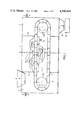
- FIG. 1 is a diagrammatic cross-sectional view showing the reducing installation
- FIG. 2 is a flow diagram showing the reducing installation of FIG. 1 in association with other parts of the plant.
- the reducing installation shown in FIG. 1 comprises a central reducing chamber 1, an input chamber 2 and an output or discharge chamber 3 separated by partitions 2a and 3a from the reducing chamber 1.
- a traveling grate 11, of the endless conveyor type, supported upon rollers 11a and 11b, is formed with compartments 12 receiving the oxidic material and passing between the upper and lower hoods 13 which are connected in series to permit the reducing gas, introduced through the valve 14, to pass upwardly and downwardly through the grate and the iron oxide a plurality of times in an upstream direction while the material travels to the right i.e. in the downstream direction.
- the valve 14 may serve to add a small quantity of methane or another hydrocarbon to the reducing gas as well.
- the valves 21 and 31 permit introduction of a less reductive coking gas to the input and output chambers 2 and 3 while funnels 22 and 32 at the input chamber and output chamber, (allowing only), to introduce the pellets and discharge the reduced products, respectively.
- the chute 32 opens directly to a briquetting unit represented at 33.
- the coking furnace 150 which, like any conventional coke battery, can comprise a plurality of coking ovens only four of which have been illustrated at 151-154.
- Distributing valves 155-158 from these coke ovens selectively deliver the gases to the lines 159 and 160, the former serving to carry the gas during the second half of the coke process while the latter carries off the gas from the first half of the coking process.
- Line 159 is provided with a pump or blower 162 and introduces the reducing gas via line 164 and valve 114 to the hoods 113 of the reducing chamber 101.
- the pump 162 also serves to raise the pressure in the reducing chamber to a slightly superatmospheric level.
- the reducing gas can be recirculated by a pump 163 as it is discharged from the chamber 101 via outlet 165 which can also be connected to a gas cleaning plant 166.
- Methane can be introduced via the valve 181 and the line 180 connected to the valve 114.
- the iron ore is preferably delivered at 171 or to some other conventional device for ensuring uniformity of particle size of the oxidic materials before they are treated with the reducing gas, the pellets being fed at 172 to the hopper 122 of the input chamber 102.
- the gases from the first half of the coking process are fed via pump 161 and valves 121, 131 to the input and output chambers 102, 103 at a pressure slightly greater than the pressure in the hoods 113, the discharged gas at 167 being fed to the gas cleaner 166.
- valves 155-158 are switched over in the succession in which each coke oven undergoes cokefication and after the lapse of the first half of the coking period to ensure that line 159 receives only the second half gases and line 160 only the first half gases.
- the reduced product is discharged through chute 132 to the briquetter 133 as previously described.
Landscapes
- Engineering & Computer Science (AREA)
- Chemical & Material Sciences (AREA)
- Manufacturing & Machinery (AREA)
- Materials Engineering (AREA)
- Metallurgy (AREA)
- Organic Chemistry (AREA)
- Manufacture Of Iron (AREA)
Abstract
A method of and an apparatus for the reduction of iron oxides continuously comprises a reducing vessel through which the iron oxide is passed and in which it is contacted with a reducing gas continuously withdrawn from a coking furnace during the second phase of the coking operation in which the effluent gas is rich in carbon monoxide and hydrogen.
Description
My present invention relates to a method of continuous reduction of iron oxides and, more particularly, the direct reduction of ore or enriched iron ores to produce sponge iron or a reduced form of the iron oxides capable of use in metallurgical plants as a raw material in the production of steel.
In recent years there has been increased interest in direct reduction processes for the preparation of iron in a form in which it can be used in more advanced metallurgical processes, namely, the production of steel. In the direct reduction of iron ores, i.e. iron oxide, it is common to utilize a mixture of about 75% hydrogen and 25% carbon monoxide as the reducing gas. The gaseous mixture is generally obtained by reacting natural gas, which preferably has been desulfurized, with water vapor in a cracking process.
However, natural gas is increasingly expensive and desirable for other purposes, limiting the degree to which it can be used in processes such as the reduction of iron oxides. Furthermore, there are many countries in which natural gas is unavailable or is available only at prohibitive cost.
It is thus the principal object of the present invention to provide a process for the continuous reduction of iron oxides which eliminates the need for natural gas in the production of the reducing gas.
Another object of the invention is to provide a method of continuously and directly reducing iron ores which yields a high quality product free from a tendency to auto-ignite and which is more economical and fuel efficient than earlier systems.
These objects and others which are obtained in accordance with the present invention can be achieved by the continuous reduction of materials containing iron oxides in a reducing reactor by subjecting the materials to the reducing action of a gas consisting predominantly of hydrogen and carbon monoxide and which is produced during the second half of the coking period of a coking furnace, the gas being fed substantially at its temperature as derived from the coking furnace to the reducing reactor.
My invention is thus based upon my discovery that the gas formed during the second half of the cokefication reaction of coal in a coking furnace contains hydrogen and carbon monoxide in proportions substantially similar to those hitherto used in direct-reduction gases derived from natural gas. This discovery is based upon measurements of the variable levels of hydrogen and carbon monoxide during the course of the coking operation and the gaseous product during the second half of the coking process is found to approach in composition the gas produced by cracking methane with water vapor. This coking gas, moreover, has practically no carbon dioxide and water vapor or levels of CO2 and H2 O which are below those of the cracking gases so that the unfavorable action of the CO2 and H2 O upon the reducing reaction is less with the system of the present invention than heretofore.
The reducing gas of the present invention consists essentially of 60 to 80% hydrogen and 20 to 40% carbon monoxide with small quantities, practically without effect on the reaction, of methane and carbon dioxide.
Furthermore, the gas is obtained from the coking furnace at a temperature between 700° C. and 900° C. which I have found is ideal for the direct reduction of the iron oxides, thereby ensuring that this gas should be fed directly from the coking furnace to the interior of the reducing reactor.
The system of the present invention has the important advantage that the energy balance of the plant is improved and energy consumption in providing the heat necessary for the reducing reaction is diminished. Heretofore, the gases formed in the coking furnace, after recuperation of heat for coking purposes, had to be cooled before these gases could be used for other purposes, e.g. heating gases, turbine-driving and the like. With the system of the present invention, the entire heat content of the reducing gas produced in the second half of the coking reaction is utilized.
According to another feature of the invention, the oxides are introduced into the reducing reactor in a calibrated form, preferably in the form of pellets of uniform size, and can be iron-ore pellets or granules or calibrated pellets or granules of oxidic metallurgical residues, such as the dust and wastes of a blast furnace or steel making plant, slag or residues from reheating furnaces or soaking pits, scale from rolling mills or the like.
According to another feature of the invention, the reduction reaction is carried out at a slightly superatmospheric pressure, i.e. the reducting gas is fed into the reactor at a slight superatmospheric pressure. Experience has shown that the reducing treatment, applied under pressure to pelletized material matter, increases the degree of reduction to more than offset the cost of pelletization and generating the elevated pressure.
According to yet another feature of the invention, a small proportion of methane or another hydrocarbon can be added to the reducing gas derived from the coking furnace. Apparently the hydrocarbon thus added cracks in the interior of the reducing vessel to deposit a fine layer of carbon upon the surface of the mineral to act as a passivation layer. This passivation layer prevents or limits the tendency toward spontaneous ignition upon contact of the pellets with the oxygen of air as they leave the furnace. It is well known that pellets reduced with gases rich in hydrogen tend to be pyrophoric.
According to yet another feature of the invention, reducing agents of high reactivity in solid form are added to the iron oxides before these materials are introduced into the reducing reactor. Such materials can include lignite-coke powder, lignite powder, dried peat powder or wood charcoal powder.
According to the invention, the reduced material is subjected to a continuous briquetting operation immediately upon its formation as it is discharged from the continuous reducing unit to increase the density of this material. The briquetting has been found to increase the ability of the material to avoid spontaneous ignition and may be used in conjunction with or as an alternative to the deposition of the passivation layer upon the material as described above. The process of the present invention thus avoids serious accidents from spontaneous ignition as have plagued earlier direct reduction systems.
The installations in which the present method is carried out may make use of any continuous reduction furnace but preferably utilizes a system of the traveling-grate type in which the oxide is carried upon an endless-type grate conveyor through a reducing chamber from an input chamber to an output chamber, the material being contacted in the reducing chamber with gas directly delivered from a coking furnace during the second half of the coking operation therein. In other words, the apparatus also includes the coking furnace and a pipe system for delivering the gases generated during the second half of a coking operation to the reducing chamber.
According to a feature of the invention, the input and output chambers are connected to a source of gas which is different from that supplied to the reducing chamber, advantageously another coking furnace. The source of the other gas may thus be a coking furnace operating in the first half of the cokefication process.
The apparatus of the present invention also advantageously includes a plurality of hoods disposed above the traveling-grate conveyor and hoods disposed below the latter for discharging the reducing gas through the grate and the pellets lying thereon, the hoods above this path collecting the gas.
This arrangement permits the hoods to be connected in series so that the reducing gas traverses the bed of the material to be reduced in a plurality of passes and increases the reduction which can be carried out by the gas.
According to another feature of the invention, means is provided to circulate the reducing gas through the reducing chamber either by evacuating the withdrawn gas or by pressurizing the introduced gas such means being dimensioned, moreover, to maintain a slight superatmospheric pressure in the reducing chamber.
The means for supplying the other gas to the input and output chambers may also be dimensioned to deliver a pressure greater than that which prevails in the hoods of the reducing chamber. The latter expedient is intended to limit the loss of the valuable reducing gas from the reducing chamber. For the reasons described above, moreover, a briquetting unit is provided directly adjacent the outlet of the reducing installation.
An apparatus for carrying out the method of the present invention has been illustrated in the accompanying drawing in which:
FIG. 1 is a diagrammatic cross-sectional view showing the reducing installation; and
FIG. 2 is a flow diagram showing the reducing installation of FIG. 1 in association with other parts of the plant.
The reducing installation shown in FIG. 1 comprises a central reducing chamber 1, an input chamber 2 and an output or discharge chamber 3 separated by partitions 2a and 3a from the reducing chamber 1.
A traveling grate 11, of the endless conveyor type, supported upon rollers 11a and 11b, is formed with compartments 12 receiving the oxidic material and passing between the upper and lower hoods 13 which are connected in series to permit the reducing gas, introduced through the valve 14, to pass upwardly and downwardly through the grate and the iron oxide a plurality of times in an upstream direction while the material travels to the right i.e. in the downstream direction.
The valve 14 may serve to add a small quantity of methane or another hydrocarbon to the reducing gas as well.
The valves 21 and 31 permit introduction of a less reductive coking gas to the input and output chambers 2 and 3 while funnels 22 and 32 at the input chamber and output chamber, (allowing only), to introduce the pellets and discharge the reduced products, respectively. The chute 32 opens directly to a briquetting unit represented at 33.
In FIG. 2, in which reference numerals corresponding to those of FIG. 1, preceded by a hundreds digit, are used to designate similarly functioning elements, I have shown the coking furnace 150 which, like any conventional coke battery, can comprise a plurality of coking ovens only four of which have been illustrated at 151-154.
Distributing valves 155-158 from these coke ovens selectively deliver the gases to the lines 159 and 160, the former serving to carry the gas during the second half of the coke process while the latter carries off the gas from the first half of the coking process.
The reducing gas can be recirculated by a pump 163 as it is discharged from the chamber 101 via outlet 165 which can also be connected to a gas cleaning plant 166. Methane can be introduced via the valve 181 and the line 180 connected to the valve 114.
The iron ore is preferably delivered at 171 or to some other conventional device for ensuring uniformity of particle size of the oxidic materials before they are treated with the reducing gas, the pellets being fed at 172 to the hopper 122 of the input chamber 102.
The gases from the first half of the coking process are fed via pump 161 and valves 121, 131 to the input and output chambers 102, 103 at a pressure slightly greater than the pressure in the hoods 113, the discharged gas at 167 being fed to the gas cleaner 166.
In operation, the valves 155-158 are switched over in the succession in which each coke oven undergoes cokefication and after the lapse of the first half of the coking period to ensure that line 159 receives only the second half gases and line 160 only the first half gases. The reduced product is discharged through chute 132 to the briquetter 133 as previously described.
Claims (8)
1. A method of reducing iron oxide material which comprises the steps of:
(a) coking coal in a coke oven for a predetermined length of time in a cokefication process and producing coke-oven gas during this length of time in said coke oven;
(b) continuously drawing hot coke-oven gas consisting predominantly of hydrogen and carbon monoxide from said coke oven during the second half of a time of said cokefication process;
(c) feeding iron oxide material to a reducing chamber separated from said coke oven;
(d) continuously contacting said iron oxide material in said chamber with said coke-oven gas drawn from said coke oven to reduce said material directly at substantially the temperature at which said coke-oven gas was drawn in step (b); and
(e) discharging the reduced material.
2. The method defined in claim 1 wherein said coke-oven gas drawn from said coke oven in step (b) consists essentially of 60 to 80% by volume hydrogen and 20 to 40% by volume carbon monoxide.
3. The method defined in claim 2 wherein the coke-oven gas drawn from said coke oven in step (b) and contacted with said iron oxide material in step (d) is at a temperature of 700° C. to 900° C.
4. The method defined in claim 1, claim 2 or claim 3 wherein said iron oxide material is selected from the group which consists of iron ore, and dust, powder or pellets containing metallurgical residues of blast furnaces and steel refining furnaces, reheating furnace particles and rolling mill scales.
5. The method defined in claim 1, claim 2 or claim 3 wherein the contact of said coke-oven gas drawn in step (b) with said material in step (d) is effected under superatmospheric pressure.
6. The method defined in claim 1, claim 2 or claim 3, further comprising the step of adding a small quantity of a hydrocarbon to said coke-oven gas as drawn in step (b) prior to contacting it with said material in step (d).
7. The method defined in claim 1, further comprising the step of mixing a solid reducing agent of high reactivity with said material proor to step (d).
8. The method defined in claim 1 or claim 3 wherein, in step (e), the reduced material is briquetted.
Applications Claiming Priority (2)
| Application Number | Priority Date | Filing Date | Title |
|---|---|---|---|
| LU81427 | 1979-06-26 | ||
| LU81427A LU81427A1 (en) | 1979-06-26 | 1979-06-26 | PROCESS AND PLANT FOR THE CONTINUOUS REDUCTION OF IRON ORE |
Publications (1)
| Publication Number | Publication Date |
|---|---|
| US4300948A true US4300948A (en) | 1981-11-17 |
Family
ID=19729185
Family Applications (1)
| Application Number | Title | Priority Date | Filing Date |
|---|---|---|---|
| US06/138,422 Expired - Lifetime US4300948A (en) | 1979-06-26 | 1980-04-08 | Method of continuous reduction of iron oxides |
Country Status (6)
| Country | Link |
|---|---|
| US (1) | US4300948A (en) |
| EP (1) | EP0022050A1 (en) |
| JP (1) | JPS565907A (en) |
| AU (1) | AU530658B2 (en) |
| BR (1) | BR8002194A (en) |
| LU (1) | LU81427A1 (en) |
Cited By (2)
| Publication number | Priority date | Publication date | Assignee | Title |
|---|---|---|---|---|
| US5713982A (en) * | 1995-12-13 | 1998-02-03 | Clark; Donald W. | Iron powder and method of producing such |
| US5972066A (en) * | 1997-04-22 | 1999-10-26 | Iron Dynamics, Inc. | Mixed bed iron reduction process |
Citations (1)
| Publication number | Priority date | Publication date | Assignee | Title |
|---|---|---|---|---|
| US3770417A (en) * | 1971-02-23 | 1973-11-06 | Salem Corp | Simultaneous production of metallized ores and coke |
Family Cites Families (6)
| Publication number | Priority date | Publication date | Assignee | Title |
|---|---|---|---|---|
| US1832731A (en) * | 1927-08-25 | 1931-11-17 | Howard J Pardee | Treatment of iron ores |
| GB1099464A (en) * | 1963-10-24 | 1968-01-17 | Alberta Res Council | Composition of matter convertible to stable metallic form by hydrogen reduction |
| DE2112369B2 (en) * | 1971-03-15 | 1973-03-15 | Steag Ag, 4300 Essen | METHOD OF OPERATING A COOK OVEN BATTERY IN CONNECTION WITH A REDUCING GAS OR. SYNTHESIS REQUIRING PLANT |
| FR2289613A1 (en) * | 1974-11-04 | 1976-05-28 | Siderurgie Fse Inst Rech | DIRECT REDUCTION OF IRON ORE PROCESS |
| DE2638348A1 (en) * | 1976-08-26 | 1978-07-13 | Didier Eng | PROCESS FOR PROCESSING COOKING GAS |
| LU79061A1 (en) * | 1978-02-14 | 1979-09-06 | Arbed | METHOD AND DEVICE FOR THE REDUCTION OF IRON ORE |
-
1979
- 1979-06-26 LU LU81427A patent/LU81427A1/en unknown
-
1980
- 1980-02-15 EP EP80630007A patent/EP0022050A1/en not_active Withdrawn
- 1980-04-08 US US06/138,422 patent/US4300948A/en not_active Expired - Lifetime
- 1980-04-09 BR BR8002194A patent/BR8002194A/en unknown
- 1980-06-25 AU AU59609/80A patent/AU530658B2/en not_active Ceased
- 1980-06-25 JP JP8530780A patent/JPS565907A/en active Pending
Patent Citations (1)
| Publication number | Priority date | Publication date | Assignee | Title |
|---|---|---|---|---|
| US3770417A (en) * | 1971-02-23 | 1973-11-06 | Salem Corp | Simultaneous production of metallized ores and coke |
Cited By (3)
| Publication number | Priority date | Publication date | Assignee | Title |
|---|---|---|---|---|
| US5713982A (en) * | 1995-12-13 | 1998-02-03 | Clark; Donald W. | Iron powder and method of producing such |
| US6569220B1 (en) | 1995-12-13 | 2003-05-27 | Donald W. Clark | Iron powder and method of producing such |
| US5972066A (en) * | 1997-04-22 | 1999-10-26 | Iron Dynamics, Inc. | Mixed bed iron reduction process |
Also Published As
| Publication number | Publication date |
|---|---|
| AU5960980A (en) | 1981-01-08 |
| JPS565907A (en) | 1981-01-22 |
| EP0022050A1 (en) | 1981-01-07 |
| BR8002194A (en) | 1980-12-30 |
| AU530658B2 (en) | 1983-07-21 |
| LU81427A1 (en) | 1979-09-12 |
Similar Documents
| Publication | Publication Date | Title |
|---|---|---|
| US4045214A (en) | Method for producing steel | |
| CA2108816C (en) | Process for producing molten pig iron or molten steel pre-products | |
| US9181594B2 (en) | Process and device for producing pig iron or liquid steel precursors | |
| US4202534A (en) | Method and apparatus for producing metallized iron ore | |
| US4380469A (en) | Process and apparatus for continuously reducing and melting metal oxides and/or pre-reduced metallic materials | |
| US5674308A (en) | Spouted bed circulating fluidized bed direct reduction system and method | |
| US5669955A (en) | Process for producing pig iron from iron ores, and applicance for the thermal and/or chemical treatment of a readily disintegrating material or for producing pig iron by means of said process | |
| US3005699A (en) | Method for converting iron oxide to magnetic oxide | |
| CN87102213A (en) | Method for producing hot sponge iron | |
| RU2211865C2 (en) | Plant for making cast iron and/or sponge cast iron and method of making cast iron and/or sponge cast iron | |
| KR850001644B1 (en) | Direct reduction device of iron using coke roges | |
| CN1003125B (en) | Process and apparatus for producing sponge iron particles and molten pig iron | |
| US4720299A (en) | Method for the direct reduction of particulate iron-oxide-containing material | |
| US4678508A (en) | Method for fluidized bed reduction of iron ore | |
| US4050990A (en) | Method and apparatus for producing form coke | |
| US2988442A (en) | Reduction of iron ore by hydrocarbons | |
| Lüngen et al. | History, developments and processes of direct reduction of iron ores | |
| US4734128A (en) | Direct reduction reactor with hot discharge | |
| US4181502A (en) | Method of producing form coke | |
| US4439233A (en) | Direct reduction of iron | |
| US3905806A (en) | Method for the direct reduction of iron ores | |
| US4897113A (en) | Direct reduction process in reactor with hot discharge | |
| US3615351A (en) | Direct gaseous reduction of iron oxide | |
| US4305788A (en) | Process for the production of molded metallurgical coke from coal briquettes | |
| US4300948A (en) | Method of continuous reduction of iron oxides |
Legal Events
| Date | Code | Title | Description |
|---|---|---|---|
| STCF | Information on status: patent grant |
Free format text: PATENTED CASE |