US4291273A - Flow regime detecting - Google Patents
Flow regime detecting Download PDFInfo
- Publication number
- US4291273A US4291273A US06/048,765 US4876579A US4291273A US 4291273 A US4291273 A US 4291273A US 4876579 A US4876579 A US 4876579A US 4291273 A US4291273 A US 4291273A
- Authority
- US
- United States
- Prior art keywords
- diametral
- conductances
- chord
- electrodes
- conduit
- Prior art date
- Legal status (The legal status is an assumption and is not a legal conclusion. Google has not performed a legal analysis and makes no representation as to the accuracy of the status listed.)
- Expired - Lifetime
Links
- 239000012530 fluid Substances 0.000 claims description 9
- 238000000034 method Methods 0.000 claims description 9
- 238000003491 array Methods 0.000 claims 1
- 230000002093 peripheral effect Effects 0.000 claims 1
- 230000005684 electric field Effects 0.000 abstract description 3
- 238000005259 measurement Methods 0.000 abstract description 3
- 239000011800 void material Substances 0.000 description 11
- 239000007788 liquid Substances 0.000 description 4
- 230000008901 benefit Effects 0.000 description 2
- 238000009835 boiling Methods 0.000 description 2
- 238000011160 research Methods 0.000 description 2
- XLYOFNOQVPJJNP-UHFFFAOYSA-N water Substances O XLYOFNOQVPJJNP-UHFFFAOYSA-N 0.000 description 2
- 238000001514 detection method Methods 0.000 description 1
- 238000010586 diagram Methods 0.000 description 1
- 230000000694 effects Effects 0.000 description 1
- 238000002848 electrochemical method Methods 0.000 description 1
- 238000011156 evaluation Methods 0.000 description 1
- 238000002474 experimental method Methods 0.000 description 1
- 239000000463 material Substances 0.000 description 1
- 238000012986 modification Methods 0.000 description 1
- 230000004048 modification Effects 0.000 description 1
- 230000035945 sensitivity Effects 0.000 description 1
- 238000012163 sequencing technique Methods 0.000 description 1
- 239000007787 solid Substances 0.000 description 1
- 238000010408 sweeping Methods 0.000 description 1
- 238000012360 testing method Methods 0.000 description 1
- 238000012546 transfer Methods 0.000 description 1
- 230000005514 two-phase flow Effects 0.000 description 1
- 230000000007 visual effect Effects 0.000 description 1
Images


Classifications
-
- G—PHYSICS
- G01—MEASURING; TESTING
- G01N—INVESTIGATING OR ANALYSING MATERIALS BY DETERMINING THEIR CHEMICAL OR PHYSICAL PROPERTIES
- G01N27/00—Investigating or analysing materials by the use of electric, electrochemical, or magnetic means
- G01N27/02—Investigating or analysing materials by the use of electric, electrochemical, or magnetic means by investigating impedance
- G01N27/22—Investigating or analysing materials by the use of electric, electrochemical, or magnetic means by investigating impedance by investigating capacitance
- G01N27/226—Construction of measuring vessels; Electrodes therefor
Definitions
- the present invention relates to determination of flow regime, an important consideration in a variety of mixed phase flows, including boiling water conduits and many other applications.
- the state of the art of flow regime determination for boiling water conduits, particularly associated with power plants is set forth in the final report (NP 118) prepared by Heat Transfer and Fluid Flow Service of the Atomic Energy Research Establishment of Harwell, England, for the Electric Power Research Institute, 3412 Hillview Avenue, Palo Alto, Cal.
- the patented apparatus was modified to overcome such problems and for purposes of flow regime now comprises, an array of electrodes around the cross-section plane of a flow conduit, substantially as described in the patent, an oscillator for sequentially exciting the electrodes, creating circumferential sequences of one transmit electrode oppositely poled with a receiver electrode creating at any given moment an electrical field which is asymmetrically arranged with respect to the flow conduit.
- Conductance can be measured between diametrally opposed electrodes and between electrodes opposed along a chord of the conduit, (i.e. the latter field being between alternate electrodes or two adjacent electrodes). Diametral conductance should be significantly lower than chord conductance under properly selected conditions and with the same conductive fluid filling all the conduction paths. The ratio of such conductances is measured.
- ratio of diametral conductance to chord conductance is greater than 1.0, this is correlatable with the absence of some of the conductive fluid between the activated electrodes constituting the chord path. Sweeping such a field circumferentially around a conduit and taking similar diametral conductance to chord conductance ratios can provide a picture of separated flow along substantial portions of a conduit wall. Conversely, ratios of diametral to chord conductance substantially below that normally encountered with a zero void conductive fluid flow indicate that there may be a central void in the flow.
- the mixed phase fluid typically comprises gas voids in a conductive liquid, but may comprise non-conductive solids as the "void" material.
- the techniques of the invention may also be applied to immiscible multiple liquid flows where there is a significant difference between conductances of the two immiscible liquids.
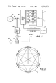
- FIG. 1 is a cross section of a conduit in which flow regime is evaluated in accordance with a preferred embodiment of the invention
- FIG. 2 is a block diagram of the system of a preferred embodiment of the invention.
- FIGS. 3A-3B, 4A-4B, et seq. are in each such A-B combination of a core cross section sketch of a particular flow regime (A) and a corresponding graphical trace (B) of diametral to chord conductance ratio versus time taken over 5 switching steps of circumferential sequencing of the electrical field to get a complete profile for one 360° scan.
- FIG. 1 shows a conduit 10 with electrodes 1, 2, 3, 4, 5, 6 therein spread in annular array therearound
- FIG. 2 shows the electrode control circuit utilized for flow regime evaluation in accordance with a preferred embodiment of the invention. While shown inside the conduit for illustration, it will be appreciated that in practice the electrodes will be integrated into the wall of the conduit as shown for instance in the patent cited above. Interconnections to the electrodes are schematically indicated at 12 and they are connectable to a single phase oscillator 14 (5-10 kilohertz) via a 5 transmit switch array 16 known per se.
- a single phase oscillator 14 (5-10 kilohertz)
- the electrodes are also connectable to a 5 receive switch array 18 also known per se to sequentially place one electrode at a time in the position of a transmit electrode (1-5) and 1 electrode at a time (2-6) (via the 5 switch array) in the position of a receive electrode, connectable to a multiplexer 24 via amplifiers 26 and absolute value circuits.
- a reference conduit 20, located close to conduit portion 10 is also provided and with a reference circuit 22 also excitable by oscillator 14 to provide a voltage to a pair of electrodes (not shown) in conduit 20 and apply a current (conductance signal) to the multiplexer 24.
- a signal 32 is developed which is varying with time and can be measured to show the current through the reference circuit and 5 receive electrodes within the conduit 10, all within a switch cycle step before changing the electrodes which are to be transmit and receiver electrodes.
- the signal 32 can be applied to an analog to digital converter and data processed, and displayed on a cathode ray tube or strip chart recorder or the like.
- the usage of the reference signal compensates for changes in bulk conductivity for consistency of result.
- FIG. 3A shows in cross section a condition of 100% (or nearly so) liquid flow in conduit 10 with no voids. Under such conditions the ratio of diametral to chord conductance displayed in FIG. 3B is substantially 1 at each step of making one of the electrodes 1-5 a transmit electrode and one of the other electrodes 2-6 a receive electrode.
- FIG. 4A shows a void formed at the center of the flow and FIG. 4B shows the resultant change in traces over the various switching steps, quite different from FIG. 3B and distinguishable therefrom.
- FIG. 5A a much larger gas center is shown compared to FIG. 4A and resultant trace of FIG. 5B is quite different from FIG. 4B.
- FIGS. 6A-6B show the appearance and the graphical representation of bubble/stratified flow with a low void fraction.
- FIGS. 7A and 7B show the effect of stratified flow with a medium void fraction and
- FIGS. 8A and 8B show stratified flow with a high void fraction.
Landscapes
- Chemical & Material Sciences (AREA)
- Chemical Kinetics & Catalysis (AREA)
- Electrochemistry (AREA)
- Physics & Mathematics (AREA)
- Health & Medical Sciences (AREA)
- Life Sciences & Earth Sciences (AREA)
- Analytical Chemistry (AREA)
- Biochemistry (AREA)
- General Health & Medical Sciences (AREA)
- General Physics & Mathematics (AREA)
- Immunology (AREA)
- Pathology (AREA)
- Investigating Or Analyzing Materials By The Use Of Electric Means (AREA)
Abstract
Description
Claims (4)
Priority Applications (1)
| Application Number | Priority Date | Filing Date | Title |
|---|---|---|---|
| US06/048,765 US4291273A (en) | 1979-06-14 | 1979-06-14 | Flow regime detecting |
Applications Claiming Priority (1)
| Application Number | Priority Date | Filing Date | Title |
|---|---|---|---|
| US06/048,765 US4291273A (en) | 1979-06-14 | 1979-06-14 | Flow regime detecting |
Publications (1)
| Publication Number | Publication Date |
|---|---|
| US4291273A true US4291273A (en) | 1981-09-22 |
Family
ID=21956338
Family Applications (1)
| Application Number | Title | Priority Date | Filing Date |
|---|---|---|---|
| US06/048,765 Expired - Lifetime US4291273A (en) | 1979-06-14 | 1979-06-14 | Flow regime detecting |
Country Status (1)
| Country | Link |
|---|---|
| US (1) | US4291273A (en) |
Cited By (4)
| Publication number | Priority date | Publication date | Assignee | Title |
|---|---|---|---|---|
| US4607228A (en) * | 1984-01-13 | 1986-08-19 | Battelle Development Corporation | Apparatus and method for measuring the concentration of solid particles in a fluid stream |
| EP0285093A3 (en) * | 1987-04-02 | 1989-12-13 | DEUTSCHES INSTITUT FÜR KAUTSCHUKTECHNOLOGIE e.V. | Method and apparatus for determining the repartition of soot in a soot-containing medium |
| US5541518A (en) * | 1994-07-13 | 1996-07-30 | Babbitt; Stewart L. | Apparatus for sensing and measuring flow of dry particulate material |
| US6686743B2 (en) | 2000-10-24 | 2004-02-03 | Univation Technologies, Llc | Apparatus for measuring the static charge of flowable solids |
Citations (1)
| Publication number | Priority date | Publication date | Assignee | Title |
|---|---|---|---|---|
| US4063153A (en) * | 1976-08-31 | 1977-12-13 | Auburn International, Inc. | Vapor liquid fraction determination |
-
1979
- 1979-06-14 US US06/048,765 patent/US4291273A/en not_active Expired - Lifetime
Patent Citations (1)
| Publication number | Priority date | Publication date | Assignee | Title |
|---|---|---|---|---|
| US4063153A (en) * | 1976-08-31 | 1977-12-13 | Auburn International, Inc. | Vapor liquid fraction determination |
Cited By (5)
| Publication number | Priority date | Publication date | Assignee | Title |
|---|---|---|---|---|
| US4607228A (en) * | 1984-01-13 | 1986-08-19 | Battelle Development Corporation | Apparatus and method for measuring the concentration of solid particles in a fluid stream |
| EP0285093A3 (en) * | 1987-04-02 | 1989-12-13 | DEUTSCHES INSTITUT FÜR KAUTSCHUKTECHNOLOGIE e.V. | Method and apparatus for determining the repartition of soot in a soot-containing medium |
| US5541518A (en) * | 1994-07-13 | 1996-07-30 | Babbitt; Stewart L. | Apparatus for sensing and measuring flow of dry particulate material |
| US5563516A (en) * | 1994-07-13 | 1996-10-08 | Babbitt; Stewart L. | Apparatus for sensing and measuring flow of dry particulate material |
| US6686743B2 (en) | 2000-10-24 | 2004-02-03 | Univation Technologies, Llc | Apparatus for measuring the static charge of flowable solids |
Similar Documents
| Publication | Publication Date | Title |
|---|---|---|
| US4101827A (en) | Method and apparatus for determining the location of a leak in a pipe buried underground | |
| Fossa | Design and performance of a conductance probe for measuring the liquid fraction in two-phase gas-liquid flows | |
| US5576617A (en) | Apparatus & method for measuring the average aspect ratio of non-spherical particles in a suspension | |
| US4493155A (en) | Apparatus for remotely indicating angular position | |
| US3096478A (en) | Apparatus with conductive gas electrodes for detecting non-uniformity in electrically insulating and electrically semi-conducting materials | |
| CN104863581B (en) | Circumferential conductivity probe sensor and system for dynamic full water value measurement in horizontal wells | |
| US4048558A (en) | Method and apparatus for detecting metal failures in situ | |
| EP0703447A2 (en) | Microwave device and method for measuring multiphase flows | |
| Levent Degertekin et al. | In situ acoustic temperature tomography of semiconductor wafers | |
| CN113848240A (en) | Gas-liquid two-phase flow section imaging device | |
| BR112015020248B1 (en) | arrangement and method for determining the phase distribution in multiphase fluids | |
| CN101650328A (en) | Measuring apparatus for multiphase fluid imaging based on bimodal silk screen and measuring method thereof | |
| US4291273A (en) | Flow regime detecting | |
| US4468155A (en) | Method and device for placing in a determined relative position two elements submerged in a conducting liquid medium | |
| US2766421A (en) | Method and apparatus for geophysical exploration | |
| US3289076A (en) | Location and repair of faults in electrical conductors | |
| US3474330A (en) | Conductivity measuring apparatus with means for comparing sampled and reference voltages | |
| WO2005031279A1 (en) | Two phase flow sensor using tomography techniques | |
| US3358229A (en) | Electrical corrosion probe having a plurality of test specimen segments | |
| EP0621488B1 (en) | A drill-probe for the measurement of the electric resistivity of a soil | |
| US6262578B1 (en) | Detection and location of current leakage paths and detection of oscillations | |
| Wang | Ultrasonic study of phase transition in calcite to 20 kilobars and 180 C | |
| WO1986002728A1 (en) | Electrode system for the measurement of corrosion rate | |
| WO2021130129A1 (en) | Magnetic induction tomography apparatus and method for monitoring a multiphase fluid | |
| Yang et al. | A transit‐time flow meter for measuring milliliter per minute liquid flow |
Legal Events
| Date | Code | Title | Description |
|---|---|---|---|
| STCF | Information on status: patent grant |
Free format text: PATENTED CASE |
|
| AS | Assignment |
Owner name: STATE STREET BANK AND TRUST COMPANY, 225, FRANKLIN Free format text: SECURITY INTEREST;ASSIGNOR:AUBURN INTERNATIONAL, INC., A CORP. OF MA.;REEL/FRAME:005390/0135 Effective date: 19900719 |
|
| AS | Assignment |
Owner name: UNITED STATES TRUST COMPANY, MASSACHUSETTS Free format text: SECURITY INTEREST;ASSIGNOR:AUBURN INTERNATIONAL, INC., A CORP. OF MA;REEL/FRAME:006279/0201 Effective date: 19920814 |
|
| AS | Assignment |
Owner name: FLEET NATIONAL BANK, MASSACHUSETTS Free format text: SECURITY AGREEMENT;ASSIGNOR:AUBURN INTERNATIONAL, INC.;REEL/FRAME:008677/0330 Effective date: 19970328 |
|
| AS | Assignment |
Owner name: SIRROM INVESTMENTS, INC., TENNESSEE Free format text: SECURITY INTEREST;ASSIGNOR:AUBURN INTERNATIONAL, INC.;REEL/FRAME:008975/0010 Effective date: 19971224 |
|
| AS | Assignment |
Owner name: AUBURN INTERNATIONAL, INC., MASSACHUSETTS Free format text: RELEASE OF SECURITY INTEREST;ASSIGNOR:UNITED STATES BANKRUPTCY COURT, DISTRICT OF MASSACHUSETTS (EASTERN DIVISION);REEL/FRAME:013333/0165 Effective date: 19990413 Owner name: OXFORD INSTRUMENTS AMERICA, INC., MASSACHUSETTS Free format text: ASSIGNMENT OF ASSIGNORS INTEREST;ASSIGNOR:AUBURN INTERNATIONAL, INC.;REEL/FRAME:013333/0247 Effective date: 19990414 |