US4284298A - Pipe coupling - Google Patents
Pipe coupling Download PDFInfo
- Publication number
- US4284298A US4284298A US06/110,551 US11055180A US4284298A US 4284298 A US4284298 A US 4284298A US 11055180 A US11055180 A US 11055180A US 4284298 A US4284298 A US 4284298A
- Authority
- US
- United States
- Prior art keywords
- disposed
- sections
- thickened portion
- pipe ends
- coupling
- Prior art date
- Legal status (The legal status is an assumption and is not a legal conclusion. Google has not performed a legal analysis and makes no representation as to the accuracy of the status listed.)
- Expired - Lifetime
Links
- 230000008878 coupling Effects 0.000 title claims abstract description 18
- 238000010168 coupling process Methods 0.000 title claims abstract description 18
- 238000005859 coupling reaction Methods 0.000 title claims abstract description 18
- 230000037431 insertion Effects 0.000 claims 1
- 238000003780 insertion Methods 0.000 claims 1
- 230000000295 complement effect Effects 0.000 description 1
- 238000010276 construction Methods 0.000 description 1
- 230000008602 contraction Effects 0.000 description 1
- 230000001419 dependent effect Effects 0.000 description 1
- 239000012530 fluid Substances 0.000 description 1
Images
Classifications
-
- F—MECHANICAL ENGINEERING; LIGHTING; HEATING; WEAPONS; BLASTING
- F16—ENGINEERING ELEMENTS AND UNITS; GENERAL MEASURES FOR PRODUCING AND MAINTAINING EFFECTIVE FUNCTIONING OF MACHINES OR INSTALLATIONS; THERMAL INSULATION IN GENERAL
- F16L—PIPES; JOINTS OR FITTINGS FOR PIPES; SUPPORTS FOR PIPES, CABLES OR PROTECTIVE TUBING; MEANS FOR THERMAL INSULATION IN GENERAL
- F16L21/00—Joints with sleeve or socket
- F16L21/06—Joints with sleeve or socket with a divided sleeve or ring clamping around the pipe ends
Definitions
- the coupling of the present invention concerns itself with the maintaining of interengaging, telescoping aligned pipe ends in a compact and sturdy relationship while allowing for expansion and contraction of the same under varying temperature conditions.
- the coupling comprises a sleeve of sufficient length formed of two semi-circular elongated sections which mate and are joined with one another to secure the aligned pipe ends.
- Each section is provided with an internal circumferential locating flange and an end flange which cooperate with a recess and the end of the outer pipe, respectively, to facilitate the locating of and assembly of the coupling with respect thereto.
- Aligned openings are provided in the respective sections for receiving removable fasteners for securing one to the other.
- the coupling sleeve 10 is comprised of two semi-circular identical sections 22, 23 having flanges 24, 25 extending inwardly from the main body thereof. Flanges 24, 24 are formed remote from ends 26, 26 of the of the sections 22, 23 while the flanges 25, 25 are formed at the opposite end thereof. Additionally, each section 22, 23 is provided with a plurality of aligned openings 27 adapted to receive suitable fasteners 28 for locking the sections together. Cutouts 29 are formed about the openings 27, in section 23 to permit a tool to be disposed therein to engage a fastener head during the fastening and unfastening stages.
- pipe end 14 of conduit 12 is forced into the enlarged portion 13 of conduit 11 until it engages stop 20 with the O-rings disposed in recesses 21 being in engagement with the interior wall of the enlarged portion 15 to provide a fluid tight seal therebetween.
- the coupling sections 22 and 23 are disposed around the enlarged portion 15 and are located by positioning the flanges 24, 24 in the complementary circumferential recess 19 and by positioning the flanges 25, 25 in engagement with the pipe end 13, and behind the thickened portion 16 of pipe 12.
- Fastener members 28 are then positioned in the aligned openings 27, 27 for securing the coupling halves together. It is apparent then, that the pipe ends 13, 16 are secured and axially aligned to one another and endwise movement is limited by the flanges 25, 25 in a simple and efficient manner.
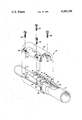
- FIGURE discloses an exploded view of the pipe ends and their relationship to one another and the manner in which the coupling sleeve cooperates therewith for locking the same together in axial alignment.
- the pipe coupling is designated generally at 10, and is used to connect two pipes, conduits or any tubular members 11, 12 of any cross-sectional configuration in end-to-end axial alignment.
- the conduits 11, 12 have respective ends 13, 14 formed as enlarged thickened portions 15, 16.
- the enlarged section 15 includes an external taper extending upwardly as at 17, from a circumferential line 18 disposed about the pipe 11 inwardly of the end 13.
- the section 15 is provided on its external surface with a circumferential keyway or recess 19 and in this instance, is of rectangular configuration which acts as a locating means for the coupling 10.
- the internal portion of the section 15 is formed with a circumferential step 20 or abutment positioned inwardly from the line 18 and is disposed inwardly from the recess 19.
- This abutment acts as a stop member for the enlarged portion 16 of the conduit 12 when the same is inserted therewithin.
- the enlarged portion 16 of the conduit 12 is formed generally in the manner as described in conjunction with portions 15 and is provided with a plurality of spaced recesses 21, 21, 21 extending inwardly from the end 14 within which O-rings of standard construction are disposed.
Landscapes
- Engineering & Computer Science (AREA)
- General Engineering & Computer Science (AREA)
- Mechanical Engineering (AREA)
- Quick-Acting Or Multi-Walled Pipe Joints (AREA)
Abstract
A pipe coupling for joining interengaging ends of a pair of pipes in axial alignment comprised of a pair of semi-circular substantially identical sections adapted to mate with one another to hold the pipe ends therein. Each of the sections have cooperating locating flanges engaging corresponding surfaces in one of the pipe ends to facilitate the assembly thereof whereafter releasable securing means are disposed in aligned openings to maintain the sections in place.
Description
A multitude of various types of couplings for joining pipe ends in end-to-end relationship have been developed over the years. The aim of most of these couplings is to provide an efficient, economical and readily manipulable coupling which can be assembled and disassembled in a minimum of time without special tools. These couplings take different shapes and forms and are in the main, dependent upon the characteristics of the pipes to be joined and the environment in which the same are to be used.
Class 285 in the U.S. Patent Office is directly solely to couplings and can be referred to for various teachings presently available to users and manufacturers.
Generally speaking, the coupling of the present invention concerns itself with the maintaining of interengaging, telescoping aligned pipe ends in a compact and sturdy relationship while allowing for expansion and contraction of the same under varying temperature conditions. The coupling comprises a sleeve of sufficient length formed of two semi-circular elongated sections which mate and are joined with one another to secure the aligned pipe ends. Each section is provided with an internal circumferential locating flange and an end flange which cooperate with a recess and the end of the outer pipe, respectively, to facilitate the locating of and assembly of the coupling with respect thereto. Aligned openings are provided in the respective sections for receiving removable fasteners for securing one to the other.
The coupling sleeve 10 is comprised of two semi-circular identical sections 22, 23 having flanges 24, 25 extending inwardly from the main body thereof. Flanges 24, 24 are formed remote from ends 26, 26 of the of the sections 22, 23 while the flanges 25, 25 are formed at the opposite end thereof. Additionally, each section 22, 23 is provided with a plurality of aligned openings 27 adapted to receive suitable fasteners 28 for locking the sections together. Cutouts 29 are formed about the openings 27, in section 23 to permit a tool to be disposed therein to engage a fastener head during the fastening and unfastening stages.
In use, pipe end 14 of conduit 12 is forced into the enlarged portion 13 of conduit 11 until it engages stop 20 with the O-rings disposed in recesses 21 being in engagement with the interior wall of the enlarged portion 15 to provide a fluid tight seal therebetween. At this point, the coupling sections 22 and 23 are disposed around the enlarged portion 15 and are located by positioning the flanges 24, 24 in the complementary circumferential recess 19 and by positioning the flanges 25, 25 in engagement with the pipe end 13, and behind the thickened portion 16 of pipe 12. Fastener members 28 are then positioned in the aligned openings 27, 27 for securing the coupling halves together. It is apparent then, that the pipe ends 13, 16 are secured and axially aligned to one another and endwise movement is limited by the flanges 25, 25 in a simple and efficient manner.
The sole FIGURE discloses an exploded view of the pipe ends and their relationship to one another and the manner in which the coupling sleeve cooperates therewith for locking the same together in axial alignment.
With reference to the drawing, the pipe coupling is designated generally at 10, and is used to connect two pipes, conduits or any tubular members 11, 12 of any cross-sectional configuration in end-to-end axial alignment. The conduits 11, 12 have respective ends 13, 14 formed as enlarged thickened portions 15, 16. In this regard, the enlarged section 15 includes an external taper extending upwardly as at 17, from a circumferential line 18 disposed about the pipe 11 inwardly of the end 13. The section 15 is provided on its external surface with a circumferential keyway or recess 19 and in this instance, is of rectangular configuration which acts as a locating means for the coupling 10. Additionally, the internal portion of the section 15 is formed with a circumferential step 20 or abutment positioned inwardly from the line 18 and is disposed inwardly from the recess 19. This abutment acts as a stop member for the enlarged portion 16 of the conduit 12 when the same is inserted therewithin. The enlarged portion 16 of the conduit 12 is formed generally in the manner as described in conjunction with portions 15 and is provided with a plurality of spaced recesses 21, 21, 21 extending inwardly from the end 14 within which O-rings of standard construction are disposed.
Claims (1)
1. A coupling for maintaining pipe ends in end-to-end axial alignment, said pipe ends being thickened with one disposed with the other, stop means being provided on the interior of the outer thickened portion to limit the extent of insertion of the other thickened portion, an annularly disposed recess disposed on the thickened portion of the outer pipe, and a plurality of spaced O-rings disposed on the inner thickened portion in engagement with the interior of the outer thickened portion, said coupling comprising a pair of substantially identical sections, each section defining a body of substantial length and having an interior annular locating flange extending inwardly from one end of the body and an annular inwardly extending flange formed at the other end, said flanges being peripherally disposed whereby when the sections are mated, the flanges will be disposed in a common plane, with the interior annular flange being disposed in said annular recess and the flange formed at the other end engaging the thickened portions of the outer and inner pipe ends, and fastening means releasably securing the sections together, said fastening means comprising aligned openings in the sections receiving removable fastener means.
Priority Applications (1)
| Application Number | Priority Date | Filing Date | Title |
|---|---|---|---|
| US06/110,551 US4284298A (en) | 1980-01-08 | 1980-01-08 | Pipe coupling |
Applications Claiming Priority (1)
| Application Number | Priority Date | Filing Date | Title |
|---|---|---|---|
| US06/110,551 US4284298A (en) | 1980-01-08 | 1980-01-08 | Pipe coupling |
Publications (1)
| Publication Number | Publication Date |
|---|---|
| US4284298A true US4284298A (en) | 1981-08-18 |
Family
ID=22333634
Family Applications (1)
| Application Number | Title | Priority Date | Filing Date |
|---|---|---|---|
| US06/110,551 Expired - Lifetime US4284298A (en) | 1980-01-08 | 1980-01-08 | Pipe coupling |
Country Status (1)
| Country | Link |
|---|---|
| US (1) | US4284298A (en) |
Cited By (32)
| Publication number | Priority date | Publication date | Assignee | Title |
|---|---|---|---|---|
| US4385644A (en) * | 1982-01-11 | 1983-05-31 | Plastonics International Inc. | Composite laminate joint structure and method and apparatus for making same |
| US4580788A (en) * | 1984-08-23 | 1986-04-08 | Foster Wheeler Energy Corporation | Split ring sealing device for high pressure service |
| EP0178360A1 (en) * | 1982-04-23 | 1986-04-23 | Victaulic Company Of America | Multiple key segmented pipe coupling |
| US4706380A (en) * | 1983-12-30 | 1987-11-17 | Fall James C | Driver apparatus |
| US4741559A (en) * | 1987-05-28 | 1988-05-03 | Berghman Earle E | Coupling protector |
| US4790058A (en) * | 1986-03-14 | 1988-12-13 | International Clamp Company | Clamp |
| US4887646A (en) * | 1988-02-18 | 1989-12-19 | The Boeing Company | Test fitting |
| US4895397A (en) * | 1986-03-14 | 1990-01-23 | International Clamp Company | Clamp |
| US5004275A (en) * | 1986-03-14 | 1991-04-02 | International Clamp Company | Clamp |
| US5066053A (en) * | 1986-03-14 | 1991-11-19 | International Clamp Company | Clamp with pipe branch |
| US5120083A (en) * | 1990-03-19 | 1992-06-09 | Henkels & Mccoy, Inc. | Expansion joint for conduit for cables |
| GB2288632A (en) * | 1994-04-04 | 1995-10-25 | Nippon Denso Co | Coupling for pipes |
| US5595410A (en) * | 1995-02-27 | 1997-01-21 | Chicago Steel Tape Co. | Quick-release locking device for telescoping member |
| US6565129B2 (en) * | 2001-06-21 | 2003-05-20 | Halliburton Energy Services, Inc. | Quick connect system and method for fluid devices |
| US8424925B2 (en) * | 2011-06-03 | 2013-04-23 | The Pipe Line Development Company | Split fitting for pipe |
| US20130192037A1 (en) * | 2012-02-01 | 2013-08-01 | Mike Muilenburg | Split Sleeve Shaft Repair |
| US20130313825A1 (en) * | 2012-05-23 | 2013-11-28 | UPSCO, Inc. | Coupler method and apparatus for installing pipe with a protective cover into borehole |
| US8820795B2 (en) | 2012-02-02 | 2014-09-02 | Victaulic Company | Fitting for joining pipe elements |
| US9182058B2 (en) | 2012-02-08 | 2015-11-10 | Victaulic Company | Fitting having receptacle of varying depth |
| US9395024B2 (en) | 2011-11-21 | 2016-07-19 | Victaulic Company | Coupling having gasket pocket of varying depth |
| US9435469B2 (en) | 2012-09-11 | 2016-09-06 | Victaulic Company | Coupling with notched projections having gasket pocket of varying depth |
| US10024467B2 (en) | 2013-07-17 | 2018-07-17 | Victaulic Company | Fittings having arcuate stiffness ribs |
| US10533688B2 (en) | 2016-05-16 | 2020-01-14 | Victaulic Company | Coupling having tabbed retainer |
| US10578234B2 (en) | 2013-05-02 | 2020-03-03 | Victaulic Company | Coupling having arcuate stiffness ribs |
| US10605394B2 (en) | 2016-05-16 | 2020-03-31 | Victaulic Company | Fitting having tabbed retainer and observation apertures |
| US10731780B2 (en) | 2016-05-16 | 2020-08-04 | Victaulic Company | Sprung coupling |
| US11060639B2 (en) | 2015-12-28 | 2021-07-13 | Victaulic Company | Adapter coupling |
| USD933173S1 (en) * | 2014-10-30 | 2021-10-12 | Somero Enterprises, Inc. | Protective shield for covering concrete hose joints |
| US11406093B2 (en) * | 2019-08-16 | 2022-08-09 | Gem Products, Inc. | Extensible pole coupling assembly |
| US20220325736A1 (en) * | 2019-10-31 | 2022-10-13 | Soltec Innovations, Sl | Construction tube |
| US11781683B2 (en) | 2019-11-15 | 2023-10-10 | Victaulic Company | Shrouded coupling |
| USD1036249S1 (en) * | 2022-03-01 | 2024-07-23 | Bizlink Industry Germany Gmbh | Fastening ring |
Citations (7)
| Publication number | Priority date | Publication date | Assignee | Title |
|---|---|---|---|---|
| US793135A (en) * | 1901-07-13 | 1905-06-27 | Robert M Kellogg | Apparatus for repairing leaks. |
| US1913030A (en) * | 1931-06-17 | 1933-06-06 | Hux Frank | Packer attaching means |
| US2490640A (en) * | 1945-01-24 | 1949-12-06 | Lefevre-Selmer Henri Leon | Pipe joint |
| US3154328A (en) * | 1961-03-10 | 1964-10-27 | Bronzavia Sa | Articulated union for pipes |
| US3482859A (en) * | 1968-11-04 | 1969-12-09 | John A Bowlin | Pipe joint |
| US4055359A (en) * | 1975-11-17 | 1977-10-25 | Ford Motor Company | Quick-connect tubular couplings |
| US4168090A (en) * | 1977-12-23 | 1979-09-18 | Kaufmann John Jun | Expansion compensating pipe coupling |
-
1980
- 1980-01-08 US US06/110,551 patent/US4284298A/en not_active Expired - Lifetime
Patent Citations (7)
| Publication number | Priority date | Publication date | Assignee | Title |
|---|---|---|---|---|
| US793135A (en) * | 1901-07-13 | 1905-06-27 | Robert M Kellogg | Apparatus for repairing leaks. |
| US1913030A (en) * | 1931-06-17 | 1933-06-06 | Hux Frank | Packer attaching means |
| US2490640A (en) * | 1945-01-24 | 1949-12-06 | Lefevre-Selmer Henri Leon | Pipe joint |
| US3154328A (en) * | 1961-03-10 | 1964-10-27 | Bronzavia Sa | Articulated union for pipes |
| US3482859A (en) * | 1968-11-04 | 1969-12-09 | John A Bowlin | Pipe joint |
| US4055359A (en) * | 1975-11-17 | 1977-10-25 | Ford Motor Company | Quick-connect tubular couplings |
| US4168090A (en) * | 1977-12-23 | 1979-09-18 | Kaufmann John Jun | Expansion compensating pipe coupling |
Cited By (44)
| Publication number | Priority date | Publication date | Assignee | Title |
|---|---|---|---|---|
| US4385644A (en) * | 1982-01-11 | 1983-05-31 | Plastonics International Inc. | Composite laminate joint structure and method and apparatus for making same |
| EP0178360A1 (en) * | 1982-04-23 | 1986-04-23 | Victaulic Company Of America | Multiple key segmented pipe coupling |
| US4706380A (en) * | 1983-12-30 | 1987-11-17 | Fall James C | Driver apparatus |
| US4580788A (en) * | 1984-08-23 | 1986-04-08 | Foster Wheeler Energy Corporation | Split ring sealing device for high pressure service |
| US4790058A (en) * | 1986-03-14 | 1988-12-13 | International Clamp Company | Clamp |
| US4895397A (en) * | 1986-03-14 | 1990-01-23 | International Clamp Company | Clamp |
| US5004275A (en) * | 1986-03-14 | 1991-04-02 | International Clamp Company | Clamp |
| US5066053A (en) * | 1986-03-14 | 1991-11-19 | International Clamp Company | Clamp with pipe branch |
| US4741559A (en) * | 1987-05-28 | 1988-05-03 | Berghman Earle E | Coupling protector |
| US4887646A (en) * | 1988-02-18 | 1989-12-19 | The Boeing Company | Test fitting |
| US5120083A (en) * | 1990-03-19 | 1992-06-09 | Henkels & Mccoy, Inc. | Expansion joint for conduit for cables |
| GB2288632A (en) * | 1994-04-04 | 1995-10-25 | Nippon Denso Co | Coupling for pipes |
| US5647612A (en) * | 1994-04-04 | 1997-07-15 | Nippondenso Co., Ltd. | Coupling for pipes |
| GB2288632B (en) * | 1994-04-04 | 1998-04-08 | Nippon Denso Co | Coupling for pipes |
| US5595410A (en) * | 1995-02-27 | 1997-01-21 | Chicago Steel Tape Co. | Quick-release locking device for telescoping member |
| US6565129B2 (en) * | 2001-06-21 | 2003-05-20 | Halliburton Energy Services, Inc. | Quick connect system and method for fluid devices |
| US8424925B2 (en) * | 2011-06-03 | 2013-04-23 | The Pipe Line Development Company | Split fitting for pipe |
| US9395024B2 (en) | 2011-11-21 | 2016-07-19 | Victaulic Company | Coupling having gasket pocket of varying depth |
| US20130192037A1 (en) * | 2012-02-01 | 2013-08-01 | Mike Muilenburg | Split Sleeve Shaft Repair |
| US8961017B2 (en) * | 2012-02-01 | 2015-02-24 | Mike Muilenburg | Split sleeve shaft repair |
| US9791083B2 (en) | 2012-02-02 | 2017-10-17 | Victaulic Company | Fitting for joining pipe elements |
| US8820795B2 (en) | 2012-02-02 | 2014-09-02 | Victaulic Company | Fitting for joining pipe elements |
| US9182058B2 (en) | 2012-02-08 | 2015-11-10 | Victaulic Company | Fitting having receptacle of varying depth |
| US9140391B2 (en) * | 2012-05-23 | 2015-09-22 | UPSCO, Inc. | Coupler method and apparatus for installing pipe with a protective cover into borehole |
| US20130313825A1 (en) * | 2012-05-23 | 2013-11-28 | UPSCO, Inc. | Coupler method and apparatus for installing pipe with a protective cover into borehole |
| US9435469B2 (en) | 2012-09-11 | 2016-09-06 | Victaulic Company | Coupling with notched projections having gasket pocket of varying depth |
| US12129941B2 (en) | 2013-05-02 | 2024-10-29 | Victaulic Company | Coupling having arcuate stiffness ribs |
| US10578234B2 (en) | 2013-05-02 | 2020-03-03 | Victaulic Company | Coupling having arcuate stiffness ribs |
| US10024467B2 (en) | 2013-07-17 | 2018-07-17 | Victaulic Company | Fittings having arcuate stiffness ribs |
| USD933173S1 (en) * | 2014-10-30 | 2021-10-12 | Somero Enterprises, Inc. | Protective shield for covering concrete hose joints |
| US11725756B2 (en) | 2015-12-28 | 2023-08-15 | Victaulic Company | Adapter coupling |
| US11060639B2 (en) | 2015-12-28 | 2021-07-13 | Victaulic Company | Adapter coupling |
| US12486929B2 (en) | 2015-12-28 | 2025-12-02 | Victaulic Company | Adapter coupling |
| US10605394B2 (en) | 2016-05-16 | 2020-03-31 | Victaulic Company | Fitting having tabbed retainer and observation apertures |
| US10731780B2 (en) | 2016-05-16 | 2020-08-04 | Victaulic Company | Sprung coupling |
| US11821546B2 (en) | 2016-05-16 | 2023-11-21 | Victaulic Company | Sprung coupling |
| US11859737B2 (en) | 2016-05-16 | 2024-01-02 | Victaulic Company | Captured element coupling |
| US11879571B2 (en) | 2016-05-16 | 2024-01-23 | Victaulic Company | Captured element coupling |
| US10533688B2 (en) | 2016-05-16 | 2020-01-14 | Victaulic Company | Coupling having tabbed retainer |
| US11125369B2 (en) | 2016-05-16 | 2021-09-21 | Victaulic Company | Coupling having tabbed retainer |
| US11406093B2 (en) * | 2019-08-16 | 2022-08-09 | Gem Products, Inc. | Extensible pole coupling assembly |
| US20220325736A1 (en) * | 2019-10-31 | 2022-10-13 | Soltec Innovations, Sl | Construction tube |
| US11781683B2 (en) | 2019-11-15 | 2023-10-10 | Victaulic Company | Shrouded coupling |
| USD1036249S1 (en) * | 2022-03-01 | 2024-07-23 | Bizlink Industry Germany Gmbh | Fastening ring |
Similar Documents
| Publication | Publication Date | Title |
|---|---|---|
| US4284298A (en) | Pipe coupling | |
| US4781400A (en) | Quick connect tube coupling | |
| US4610468A (en) | Quick connect/disconnect coupling | |
| US4067534A (en) | Pipe coupler assembly | |
| JPH0317112Y2 (en) | ||
| US3449003A (en) | Snap coupling | |
| US5269572A (en) | Apparatus and method for coupling elongated members | |
| EP0213505B1 (en) | Pipe coupling | |
| JP2588417B2 (en) | Piping connector | |
| US4588214A (en) | Couplings for tubes and other fluid handling components | |
| GB1513849A (en) | Quick connect coupling assemblies | |
| JPH01320393A (en) | hose fittings | |
| US2453024A (en) | Coupling | |
| MY109237A (en) | Jointing device for a corrugated flexible conduit | |
| ES2111366T3 (en) | TUBE JOINT ASSEMBLY. | |
| JPH086869B2 (en) | Pipe fitting | |
| GB2314132A (en) | Sleeve for quick disconnect coupling | |
| US5524940A (en) | Pipe coupler device | |
| US5120092A (en) | Apparatus to provide a threaded coupling for a broken pipe | |
| DE3260281D1 (en) | Socket end | |
| US5178483A (en) | Coupling device | |
| US5208569A (en) | Simplified flangeless unisex waveguide coupler assembly | |
| JP2669723B2 (en) | Expansion joint | |
| US5257836A (en) | Stab joint coupler | |
| JPH0512596B2 (en) |
Legal Events
| Date | Code | Title | Description |
|---|---|---|---|
| STCF | Information on status: patent grant |
Free format text: PATENTED CASE |