US4280706A - Seal for fluidizing outlet - Google Patents
Seal for fluidizing outlet Download PDFInfo
- Publication number
- US4280706A US4280706A US06/104,343 US10434379A US4280706A US 4280706 A US4280706 A US 4280706A US 10434379 A US10434379 A US 10434379A US 4280706 A US4280706 A US 4280706A
- Authority
- US
- United States
- Prior art keywords
- seal
- outlet
- hopper
- projection
- fluidizing
- Prior art date
- Legal status (The legal status is an assumption and is not a legal conclusion. Google has not performed a legal analysis and makes no representation as to the accuracy of the status listed.)
- Expired - Lifetime
Links
Images
Classifications
-
- B—PERFORMING OPERATIONS; TRANSPORTING
- B61—RAILWAYS
- B61D—BODY DETAILS OR KINDS OF RAILWAY VEHICLES
- B61D7/00—Hopper cars
- B61D7/14—Adaptations of hopper elements to railways
- B61D7/16—Closure elements for discharge openings
- B61D7/22—Sealing means thereof
-
- Y—GENERAL TAGGING OF NEW TECHNOLOGICAL DEVELOPMENTS; GENERAL TAGGING OF CROSS-SECTIONAL TECHNOLOGIES SPANNING OVER SEVERAL SECTIONS OF THE IPC; TECHNICAL SUBJECTS COVERED BY FORMER USPC CROSS-REFERENCE ART COLLECTIONS [XRACs] AND DIGESTS
- Y10—TECHNICAL SUBJECTS COVERED BY FORMER USPC
- Y10S—TECHNICAL SUBJECTS COVERED BY FORMER USPC CROSS-REFERENCE ART COLLECTIONS [XRACs] AND DIGESTS
- Y10S277/00—Seal for a joint or juncture
- Y10S277/918—Seal combined with filter or fluid separator
Definitions
- a seal between a railway hopper and a hopper outlet including projections or protuberances which aid in achieving a seal between the hopper and the outlet, and bevelled portions located at the inner ends of the seal which aid in directing lading down the outlet walls.
- U.S. Pat. No. 3,807,318 discloses a gravity outlet having a seal in which the lading and pressure in the car urge a lower inner lip into engagement with a gravity gate.
- the seal is used in a fluidizing outlet which includes a metal sheet containing at least one opening through which the fluidizing medium passes and a layer of filter material resting thereon to remove impurities in the fluid.
- the ends of the sheet and filter layer are held in place by fasteners extending through the hopper and outlet mounting flanges.
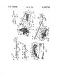
- FIG. 1 is a schematic perspective bottom view of the outlet of the present invention mounted upon a hopper;
- FIG. 2 is a partial plan view of the outlet of the present invention after the hopper and the outlet have been rotated 180° from the position shown in FIG. 1.
- FIG. 3 is a partial side elevation view of FIG. 2.
- FIG. 4 is a sectional view looking in the direction of the arrows along the line 4--4 in FIG. 2.
- FIG. 5 is a view looking in the direction of the arrows along the line 5--5 in FIG. 2.
- FIG. 7 is a detail view of the lower member of the seal member illustrated in FIG. 6.
- a hopper 1 includes sloping side walls 2 and 3 and end walls 4 and 5. The hopper in upright position is supported by a suitable frame structure (not shown).
- a fluidizing outlet is indicated in the drawings generally at 10. This outlet includes a mounting flange 12 having openings therein 14 to receive fasteners 48 to hold the outlet in place upon a hopper 1.
- Hopper 1 includes a mounting flange 18 and a vertical wall portion 20.
- a metal sheet 22 includes a plurality of openings 24 through which a fluidizing medium passes to fluidize the lading.
- a filter 26 is located upon the metal sheet. The metal sheet has an inner end 28 and the filter has an inner end 30 which is located between the outlet flange 12 and a hopper flange 18.
- a seal member indicated generally at 32 includes a body portion 34 located upon filter member 30 and below outlet flange 18.
- the seal includes a vertical projection 36 which engages the hopper wall portion 20.
- the seal further includes a tapered portion 38 which is tapered downwardly and inwardly from the projection 36 which terminates at 40 above the sheet inner end 28. It will be apparent that fluid pressure in the outlet will tend to urge the projection 36 into engagement with the vertical wall 20 and urge the tapered portion 38 into engagement with the filter inner end 30 to provide a tight seal.
- a void space 42 may be provided located generally below the projection 38 which can be compressed to some extent during assembly to reduce inconsistencies and unevenness in the filter, the metal sheet or the flanges, and to ensure a tight seal between filter 26 and hopper wall 20.
- a projection 44 including a hollow portion 46 is located on body portion 34. The purpose of this projection 44 is to allow for discontinuities and unevenness in assembly when a fastener 48 is used to tighten the assembly of the hopper flange portion 12, the filter member 30, the seal 32 and the hopper flange portion 18.
- a second projection 50 is conveniently provided at the inner end of the seal, again including an opening 52 which is compressed in assembly as shown in FIG. 4.
- a lower seal member 54 including a body portion 56 is located below filter portion 30 conveniently including a projection 58 having an opening 60 which is compressed in assembly and further including an upwardly extending lug 62.
- the upper filter member includes a depending lug 64 which abuts lug 62.
- the lower seal member conveniently includes another projection 66 at its outer end including an opening 68 which is compressed in assembly. A nut 49 holds the assembly together.
- Metal sheet 28 is conveniently though not essentially located outboard of lower seal member 54.
- seal projection 36 and the taper 38 provide an assembly whereby the fluid pressure within the outlet will urge the seal member into sealing engagement with the outlet wall 20 and the tapered portion 38 into engagement with the filter 26.
- the projections 44, 50, 58 and 66 allow for discontinuities and unevenness in the abutting flanges 12 and 18 in the steel sheet end 28 and in the end of the filter member 30.
- a pipe 70 including a 90° bend 72 is connected to a source (not shown) of fluidizing air.
- Pipe 70 includes a portion 74 extending horizontally into the outlet.
- An opening 76 at the inner end distributes the fluid into the outlet below sheet 22.
- An outlet stiffener 78 extends transversely of the outlet transversely of the car.
- Another stiffener 80 extends perpendicular to stiffener 78 and includes a generally inclined portion 82.
- Inclined portion 82 includes an upper surface 84 and an opening 86 (FIG. 5) for fluid to pass through into compartment portion 88.
- Stiffeners 78, 80 and 82 support the metal sheet and the filter medium in the body portion of the outlet.
- the outlet includes tapered bottom walls 83, 84, 85 and 86; 83', 84', 85' and 86'.
- the outlet is constructed in a similar manner on the other side of the outlet above bottom wall 85 including metal sheet 22', filter member 26', outlet wall flange portion 18' and seal portion 38'.
- the seal assembly 90 includes an upper member 91 having a body portion 92 having a projection 94 at its outer end and a taper 96 as described above.
- the projection 94 extends at an angle of less than 90° with respect to the body portion 92.
- a vertical portion 98 is provided which includes an inwardly extending lip 100. The distance between the vertical portion 98 and the projection 94 is such that the outlet flange portion 18 will just fit therebetween.
- seal portions 98 and 100 are essentially assembly locating members.
- void space 42 provided in the embodiment shown in FIG.
- a lower seal member 110 is further provided including a discontinuity projection 112 having an opening 114 and another discontinuity projection 116 having an opening 118.
- the lower member 110 is provided with a downwardly extending vertical portion 120 also having an inwardly extending lip 122 sized appropriately to engage the outlet flange inner end to again aid in assembly.
- a depending lug 124 located on the upper member and an upwardly extending lug 126 located on the lower member are aligned above one another in assembly and are separated by the inner end 30 of filter 26.
- fluidizing air is introduced through pipe 70 into horizontal conduit 74 and into the outlet.
- the air passes through openings 78a and 86 in stiffeners 78 and 80 to reach all parts of the outlet.
- the air passes through the metal sheet openings 24 and through the filter member 26 to fluidize the lading in the outlet.
- the lading is removed through an outlet 128 (FIG. 3) and into a product line connected thereto 130 (FIG. 2). From here it is transferred into a container therefor.
Landscapes
- Engineering & Computer Science (AREA)
- Transportation (AREA)
- Mechanical Engineering (AREA)
- Filtration Of Liquid (AREA)
Abstract
Description
Claims (20)
Priority Applications (1)
| Application Number | Priority Date | Filing Date | Title |
|---|---|---|---|
| US06/104,343 US4280706A (en) | 1979-12-17 | 1979-12-17 | Seal for fluidizing outlet |
Applications Claiming Priority (1)
| Application Number | Priority Date | Filing Date | Title |
|---|---|---|---|
| US06/104,343 US4280706A (en) | 1979-12-17 | 1979-12-17 | Seal for fluidizing outlet |
Publications (1)
| Publication Number | Publication Date |
|---|---|
| US4280706A true US4280706A (en) | 1981-07-28 |
Family
ID=22299996
Family Applications (1)
| Application Number | Title | Priority Date | Filing Date |
|---|---|---|---|
| US06/104,343 Expired - Lifetime US4280706A (en) | 1979-12-17 | 1979-12-17 | Seal for fluidizing outlet |
Country Status (1)
| Country | Link |
|---|---|
| US (1) | US4280706A (en) |
Cited By (7)
| Publication number | Priority date | Publication date | Assignee | Title |
|---|---|---|---|---|
| US4428585A (en) | 1982-04-16 | 1984-01-31 | Acf Industries, Incorporated | Permeable membrane seal assembly |
| US4846377A (en) * | 1987-05-04 | 1989-07-11 | Acf Industries, Incorporated | Limp, porous membrane for a fluidized outlet |
| US5314094A (en) * | 1993-04-29 | 1994-05-24 | Acf Industries, Incorporated | Cloth fluidizing membrane for hopper car outlet |
| US5829358A (en) * | 1996-12-18 | 1998-11-03 | Central Sales & Service, Inc. | Dual durometer gasket for a railroad hopper car |
| US6237505B1 (en) | 1998-04-22 | 2001-05-29 | Trn Business Trust | Large capacity car body for pressure discharge railway hopper cars |
| US6273647B1 (en) | 1998-04-22 | 2001-08-14 | Trn Business Trust | Pressure discharge railway hopper car |
| US6393997B1 (en) | 1999-03-18 | 2002-05-28 | Trn Business Trust | Aerator pad assembly for railway hopper cars |
Citations (8)
| Publication number | Priority date | Publication date | Assignee | Title |
|---|---|---|---|---|
| US1251683A (en) * | 1917-09-04 | 1918-01-01 | Louis G Miller | Reinforcing and hinge plate for cars. |
| US2360345A (en) * | 1942-04-18 | 1944-10-17 | Chain Belt Co | Charging means for transit mixers |
| CA723878A (en) * | 1965-12-21 | The General Tire And Rubber Company | Fluid sealing device for washers and the like | |
| US3485183A (en) * | 1967-04-17 | 1969-12-23 | Midland Ross Corp | Railway hopper gate flexible operating assembly with resilient gate sealing means |
| US3621793A (en) * | 1969-10-24 | 1971-11-23 | Midland Ross Corp | Plastically and resiliently sealed railway hopper gate assembly |
| US3807318A (en) * | 1972-06-01 | 1974-04-30 | Holland Co | Resilient hopper car outlet gate seal |
| US3831803A (en) * | 1972-12-04 | 1974-08-27 | Pullman Inc | Resiliently mounted railway hopper car outlet |
| DE2734186A1 (en) * | 1977-07-29 | 1979-02-08 | Linke Hofmann Busch | Railway gable-bottomed wagon unloader flap seal - is inverted U=shaped elastic profile vulcanised between steel bars |
-
1979
- 1979-12-17 US US06/104,343 patent/US4280706A/en not_active Expired - Lifetime
Patent Citations (8)
| Publication number | Priority date | Publication date | Assignee | Title |
|---|---|---|---|---|
| CA723878A (en) * | 1965-12-21 | The General Tire And Rubber Company | Fluid sealing device for washers and the like | |
| US1251683A (en) * | 1917-09-04 | 1918-01-01 | Louis G Miller | Reinforcing and hinge plate for cars. |
| US2360345A (en) * | 1942-04-18 | 1944-10-17 | Chain Belt Co | Charging means for transit mixers |
| US3485183A (en) * | 1967-04-17 | 1969-12-23 | Midland Ross Corp | Railway hopper gate flexible operating assembly with resilient gate sealing means |
| US3621793A (en) * | 1969-10-24 | 1971-11-23 | Midland Ross Corp | Plastically and resiliently sealed railway hopper gate assembly |
| US3807318A (en) * | 1972-06-01 | 1974-04-30 | Holland Co | Resilient hopper car outlet gate seal |
| US3831803A (en) * | 1972-12-04 | 1974-08-27 | Pullman Inc | Resiliently mounted railway hopper car outlet |
| DE2734186A1 (en) * | 1977-07-29 | 1979-02-08 | Linke Hofmann Busch | Railway gable-bottomed wagon unloader flap seal - is inverted U=shaped elastic profile vulcanised between steel bars |
Cited By (7)
| Publication number | Priority date | Publication date | Assignee | Title |
|---|---|---|---|---|
| US4428585A (en) | 1982-04-16 | 1984-01-31 | Acf Industries, Incorporated | Permeable membrane seal assembly |
| US4846377A (en) * | 1987-05-04 | 1989-07-11 | Acf Industries, Incorporated | Limp, porous membrane for a fluidized outlet |
| US5314094A (en) * | 1993-04-29 | 1994-05-24 | Acf Industries, Incorporated | Cloth fluidizing membrane for hopper car outlet |
| US5829358A (en) * | 1996-12-18 | 1998-11-03 | Central Sales & Service, Inc. | Dual durometer gasket for a railroad hopper car |
| US6237505B1 (en) | 1998-04-22 | 2001-05-29 | Trn Business Trust | Large capacity car body for pressure discharge railway hopper cars |
| US6273647B1 (en) | 1998-04-22 | 2001-08-14 | Trn Business Trust | Pressure discharge railway hopper car |
| US6393997B1 (en) | 1999-03-18 | 2002-05-28 | Trn Business Trust | Aerator pad assembly for railway hopper cars |
Similar Documents
| Publication | Publication Date | Title |
|---|---|---|
| US4091743A (en) | Floor structure for refrigerated vehicles | |
| US4280706A (en) | Seal for fluidizing outlet | |
| US3645583A (en) | Apparatus and method for handling finely divided solids | |
| US3708209A (en) | Pneumatic hopper outlet for railway cars | |
| US3659752A (en) | Easily removable fluid permeable structure for aerated hopper discharge outlets | |
| EP0054340A1 (en) | Particulate solid storage container | |
| US5676404A (en) | Low profile flanged tee | |
| US3583768A (en) | Aerated hopper discharge apparatus for railroad cars | |
| US4568224A (en) | Fluidizing outlet assembly including internal trough | |
| US3289396A (en) | Pressure equalizing and filter arrangement for pressurized storage tanks having voids therein | |
| US4880148A (en) | Fluidization kit for pneumatic discharge outlet | |
| EP0293051B1 (en) | A passage connection between steadily intercoupled railway cars | |
| CA2141286C (en) | Truck mounted tank having low center of gravity | |
| CA1316401C (en) | Internal drainage system for hollow member structural | |
| US3127851A (en) | Railway hopper cars | |
| US3194144A (en) | Vent structure for pneumatically discharged hopper car | |
| US2095460A (en) | Tank car | |
| US3554609A (en) | Pneumatic outlet for a hopper | |
| US2665949A (en) | Tilted container | |
| US2569493A (en) | Vehicle fuel tank assembly | |
| US4036532A (en) | Fluidizing outlet | |
| US2464183A (en) | Pneumatically unloadable shipping container | |
| US2789739A (en) | Outlet valve for hoppers | |
| US3459457A (en) | Silo filling attachment for an air sealed silo having a dome shaped roof | |
| US3162490A (en) | Hopper outlet construction |
Legal Events
| Date | Code | Title | Description |
|---|---|---|---|
| STCF | Information on status: patent grant |
Free format text: PATENTED CASE |
|
| AS | Assignment |
Owner name: NATIONAL WESTMINSTER BANK USA, A NATIONAL BANKING Free format text: SECURITY INTEREST;ASSIGNOR:ACF INDUSTRIES, INCORPORATED;REEL/FRAME:004307/0396 Owner name: NATIONAL WESTMINSTER BANK USA, A NATIONAL BANKING ASSOCIATION, 175 WATER STREET, NEW YORK NEW YORK Free format text: SECURITY INTEREST;ASSIGNOR:ACF INDUSTRIES, INCORPORATED;REEL/FRAME:004307/0396 |
|
| AS | Assignment |
Owner name: ACF INDUSTRIES, INCORPORATED, 750 THIRD AVENUE, NE Free format text: RECONVEYS ALL LETTERS PATENTS BACK TO BORROWER RECITED IN REEL 4307FRAMES 396 AND 397 RECORED OCT. 2, 1984 (LOAN HAS BEEN PAID IN FULL);ASSIGNOR:NATIONAL WESTMINSTER BANK USA, AS AGENT;REEL/FRAME:004365/0266 Effective date: 19841220 |
|
| AS | Assignment |
Owner name: AMERICAN RAILCAR INDUSTRIES, INC., MISSOURI Free format text: SECURITY INTEREST;ASSIGNOR:ACF INDUSTRIES, INCORPORATED;REEL/FRAME:008744/0054 Effective date: 19971003 |