US4279576A - Rotating speed detecting device of a turbocharger - Google Patents
Rotating speed detecting device of a turbocharger Download PDFInfo
- Publication number
- US4279576A US4279576A US06/052,858 US5285879A US4279576A US 4279576 A US4279576 A US 4279576A US 5285879 A US5285879 A US 5285879A US 4279576 A US4279576 A US 4279576A
- Authority
- US
- United States
- Prior art keywords
- shaft
- turbocharger
- wall
- circumferential outer
- detector
- Prior art date
- Legal status (The legal status is an assumption and is not a legal conclusion. Google has not performed a legal analysis and makes no representation as to the accuracy of the status listed.)
- Expired - Lifetime
Links
- 239000007769 metal material Substances 0.000 claims description 3
- 229910010293 ceramic material Inorganic materials 0.000 claims description 2
- 238000004891 communication Methods 0.000 claims description 2
- 238000010276 construction Methods 0.000 description 2
- 230000008878 coupling Effects 0.000 description 2
- 238000010168 coupling process Methods 0.000 description 2
- 238000005859 coupling reaction Methods 0.000 description 2
- 238000002485 combustion reaction Methods 0.000 description 1
- 230000006378 damage Effects 0.000 description 1
- 238000012986 modification Methods 0.000 description 1
- 230000004048 modification Effects 0.000 description 1
- 238000007789 sealing Methods 0.000 description 1
- 230000001960 triggered effect Effects 0.000 description 1
Images


Classifications
-
- F—MECHANICAL ENGINEERING; LIGHTING; HEATING; WEAPONS; BLASTING
- F02—COMBUSTION ENGINES; HOT-GAS OR COMBUSTION-PRODUCT ENGINE PLANTS
- F02B—INTERNAL-COMBUSTION PISTON ENGINES; COMBUSTION ENGINES IN GENERAL
- F02B39/00—Component parts, details, or accessories relating to, driven charging or scavenging pumps, not provided for in groups F02B33/00 - F02B37/00
-
- F—MECHANICAL ENGINEERING; LIGHTING; HEATING; WEAPONS; BLASTING
- F02—COMBUSTION ENGINES; HOT-GAS OR COMBUSTION-PRODUCT ENGINE PLANTS
- F02B—INTERNAL-COMBUSTION PISTON ENGINES; COMBUSTION ENGINES IN GENERAL
- F02B37/00—Engines characterised by provision of pumps driven at least for part of the time by exhaust
-
- Y—GENERAL TAGGING OF NEW TECHNOLOGICAL DEVELOPMENTS; GENERAL TAGGING OF CROSS-SECTIONAL TECHNOLOGIES SPANNING OVER SEVERAL SECTIONS OF THE IPC; TECHNICAL SUBJECTS COVERED BY FORMER USPC CROSS-REFERENCE ART COLLECTIONS [XRACs] AND DIGESTS
- Y02—TECHNOLOGIES OR APPLICATIONS FOR MITIGATION OR ADAPTATION AGAINST CLIMATE CHANGE
- Y02T—CLIMATE CHANGE MITIGATION TECHNOLOGIES RELATED TO TRANSPORTATION
- Y02T10/00—Road transport of goods or passengers
- Y02T10/10—Internal combustion engine [ICE] based vehicles
- Y02T10/12—Improving ICE efficiencies
-
- Y—GENERAL TAGGING OF NEW TECHNOLOGICAL DEVELOPMENTS; GENERAL TAGGING OF CROSS-SECTIONAL TECHNOLOGIES SPANNING OVER SEVERAL SECTIONS OF THE IPC; TECHNICAL SUBJECTS COVERED BY FORMER USPC CROSS-REFERENCE ART COLLECTIONS [XRACs] AND DIGESTS
- Y10—TECHNICAL SUBJECTS COVERED BY FORMER USPC
- Y10T—TECHNICAL SUBJECTS COVERED BY FORMER US CLASSIFICATION
- Y10T403/00—Joints and connections
- Y10T403/21—Utilizing thermal characteristic, e.g., expansion or contraction, etc.
- Y10T403/217—Members having different coefficients of expansion
Definitions
- the present invention relates to a rotating speed detecting device of a turbocharger.
- An object of the present invention is to provide a rotating speed detecting device capable of ensuring the smooth flow of the suction air and also capable of avoiding the danger of destroying the blades of the compressor wheel in the case wherein the detector is destroyed.
- FIG. 3 is a graph showing changes in voltage.
- the detector since the detector is not arranged in the flow passage of the suction air, the detector does not prevent the suction air from flowing smoothly into the compressor and, thus, there is no danger that the efficiency of the turbocharger is reduced.
- the rotating speed of the turbocharger is detected by using the locknut of the compressor wheel as in a conventional rotating speed detecting derive, it is necessary to support the detector by means of a support member.
- a support member is not necessary.
Landscapes
- Engineering & Computer Science (AREA)
- Chemical & Material Sciences (AREA)
- Combustion & Propulsion (AREA)
- Mechanical Engineering (AREA)
- General Engineering & Computer Science (AREA)
- Supercharger (AREA)
- Linear Or Angular Velocity Measurement And Their Indicating Devices (AREA)
Abstract
A rotating speed detecting device of a turbocharger comprising the compressor wheel and the turbine wheel which are fixed onto the opposed ends of the rotary shaft. A hole is formed on the central portion of the shaft. An electromagnetic detector is arranged in the vicinity of the central portion of the shaft so that the detecting head of the detector can face the hole of the shaft.
Description
The present invention relates to a rotating speed detecting device of a turbocharger.
As is well known to those skilled in the art, a turbocharger is used, for example, for increasing the output power of an internal combustion engine. In such a turbocharger, the rotating speed of the turbocharger is normally detected in such a way that the detecting portion of the electromagnetic detector is arranged in the vicinity of the locknut used for fixing the compressor wheel onto the rotary shaft of the turbocharger so that the change in the magnetic reluctance of the magnetic circuit formed by the locknut, the core of the detecting head of the detector and the air gap formed therebetween is detected by the detector. However, in this case, since it is necessary to position the detector within the air inlet of the compressor, the detector prevents the suction air from flowing smoothly into the compressor and, at the same time, the presence of the detector causes a turbulence in the suction air. This results in a problem in that the efficiency of the turbocharger is reduced. In addition, in the case wherein the locknut is loosened and, as a result, the detector comes into contact with the locknut and is destroyed, there is a danger that destroyed pieces of the detector will strike upon the blades of the compressor wheel which are rotating at a high speed and cause the destruction of the blades of the compressor wheel.
An object of the present invention is to provide a rotating speed detecting device capable of ensuring the smooth flow of the suction air and also capable of avoiding the danger of destroying the blades of the compressor wheel in the case wherein the detector is destroyed.
According to the present invention, there is provided a turbocharger, comprising: a housing; a shaft rotatably mounted on said housing and extending through said housing, said shaft having at its opposed ends a compressor wheel and a turbine wheel and having a circumferential outer wall which is located between said compressor wheel and said turbine wheel and forms at least one recessed portion thereon, and; detecting means mounted on said housing and having a detecting portion which is arranged to face said recessed portion in the vicinity of the circumferential outer wall of said shaft.
The present invention may be more fully understood from the description of a preferred embodiment of the invention set forth below, together with the accompanying drawings.
In the drawings:
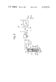
FIG. 1 is a cross-sectional side view of a turbocharger according to the present invention;
FIG. 2 is a cross-sectional side view of a part of the turbocharger, taken along line II--II in FIG. 1, and;
FIG. 3 is a graph showing changes in voltage.
Referring to FIG. 1, 1 designates an engine body, 2 an intake manifold, 3 a carburetor, 4 an exhaust manifold and 5 a turbocharger. The turbocharger 5 has in its housing 6 a rotary shaft 8 rotatably supported by a pair of bearings 7, and a centrifugal compressor wheel 9 and a turbine wheel 10 which are fixed onto the opposed ends of the rotary shaft 8. A compressed air delivery chamber 11 of the compressor C is connected to the intake manifold 2 via an air duct 12 and the carburetor 3, and the exhaust manifold 4 is connected to an exhaust gas inflow chamber 14 of the turbine T via an exhaust duct 13. The turbocharger 5 further comprises a thrust bearing 15, a thrust ring 16, an oil deflector 17, a sleeve 18, an insert 19, a snap ring 20 and a sealing ring 21 in the housing 6. When the engine is operating, the air compressed by the rotating motion of the compressor wheel 9 is fed into the cylinders of the engine via the air duct 12, and the exhaust gas discharged from the cylinders of the engine is discharged into the atmosphere after the exhaust gas provides the rotating force to turn the turbine wheel 10.
As illustrated in FIG. 1, the rotary shaft 8 comprises a pair of shaft portions 8a and 8b, and the shaft portion 8a is made of metallic material. The compressor wheel 9 is fixed onto one end of the shaft portion 8a by means of a nut 22, and a cylindrical hole 23 is formed on the other end of the shaft portion 8a. On the other hand, the shaft portion 8b is formed in one piece on the rear face of the turbine wheel 10 and has on its inner end a reduced diameter portion 24. In addition, the shaft portion 8b and the turbine wheel 10 are made of ceramic material. As illustrated in FIG. 1, the reduced diameter portion 24 of the shaft portion 8b is shrinkage-fitted into the cylindrical hole 23 of the shaft portion 8a so that the shaft portions 8a and 8b are rigidly interconnected to each other. In addition, an air vent 25 which is in communication with the deep interior of the cylindrical hole 23 is formed on the outer circumferential wall of the shaft portion 8a. When the shaft portions 8a and 8b are assembled into the housing 6 of the turbocharger 5, by forming the air vent 25 as mentioned above, the reduced diameter portion 24 of the shaft portion 8b can be easily shrinkage-fitted into the cylindrical hole 23 of the shaft portion 8a. An electromagnetic detector 27 is screwed into a threaded hole 26 formed on the housing 6, and the detector 27 is secured onto the housing 6 by means of a nut 29 so that a detecting portion 28 formed at the tip of the detector 27 is positioned in the vicinity of the outer circumferential wall of the shaft portion 8a and can face the air vent 25.
As illustrated in FIG. 2, inside the detector 27 there is a detecting head comprising a core 30 and a coil 31, and the opposed ends of the coil 31 are connected to corresponding external terminals 32 and 33. The external terminal 32 is connected to the ground via a resistor 34 on one hand and to the input of a wave form shaper 36 via a coupling condenser 35 on the other hand. In this embodiment, the wave form shaper 36 comprises a monostable multivibrator. In addition, the external terminal 33 is connected to a power source 37. The output of the wave form shaper 36 is connected to the input of a frequency-voltage converter 39 via a coupling condenser 38, and the output of the frequency-voltage converter 39 is connected to a tachometer 41 via a resistor 40. When the shaft portion 8a is rotating, the magnetic reluctance of the magnetic circuit formed by the core 30, the shaft portion 8a and the air gap formed therebetween is changed everytime the air vent 25 faces the detecting portion 28 of the detector 27. As a result of this, the voltage as shown in FIG. 3(a) is produced on the external terminal 32. In FIGS. 3(a) and (b), the ordinate V indicates voltage, and the abscissa T indicates time. The wave form shaper 36 is triggered by the falling portion of the voltage produced on the external terminal 32 and produces a pulse having a constant width as illustrated in FIG. 3(b). The frequency-voltage converter 39 produces a voltage having a level which is proportional to the frequency of the pulse and, thus, the number of revolutions per minite of the rotary shaft 8 can be detected by the tachometer 41.
It is preferable that the diameter of the air vent 25 formed on the shaft portion 8a be equal to or slightly larger than the distance between the projecting tips of the core 30. In addition, in the embodiment illustrated in FIG. 1, the single air vent 25 is formed on the shaft portion 8a. However, instead of forming the single air vent 25, a plurality of air vents equally spaced along the circumferential outer wall of the shaft portion 8a may be formed on the shaft portion 8a. Furthermore, instead of using a detector having the construction of the detector 27 illustrated in FIG. 2, a detector having any other construction may be used.
According to the present invention, since the detector is not arranged in the flow passage of the suction air, the detector does not prevent the suction air from flowing smoothly into the compressor and, thus, there is no danger that the efficiency of the turbocharger is reduced. In addition, in the case wherein the rotating speed of the turbocharger is detected by using the locknut of the compressor wheel as in a conventional rotating speed detecting derive, it is necessary to support the detector by means of a support member. However, in the present invention, such a support member is not necessary. Furthermore, in a conventional speed detecting device, since the irregurality in the shape of the locknut of the compressor wheel disturbs the wave form of the detecting signal of the detector, there is a danger that the number of revolutions per minute of the tarbocharger will not be detected correctly. However, in the present invention, even if the diameter and the position of the air vent are different from the predetermined diameter and position, the output voltage of the detector, which sharply varies, can be obtained and, thus, the correct number of revolutions per minute of the turbocharger can be always obtained. In addition, in the present invention, even if the locknut of the detector is loosened and, as a result, the detector comes into contact with the ratary shaft and is destroyed, there is no danger that destroyed pieces of the detector will strike the blades of the compressor wheel and the turbine wheel.
While the invention has been described by reference to a specific embodiment chosen for purposes of illustration, it should be apparent that numerous modifications could be made thereto by those skilled in the art without departing from the spirit and scope of the invention.
Claims (6)
1. A turbocharger comprising:
a housing;
a shaft rotatably mounted on said housing and extending through said housing, said shaft having at its opposed ends a compressor wheel and a turbine wheel and having a circumferential outer wall which is located between said compressor wheel and said turbine wheel and forms at least one recessed portion thereon, said shaft comprises a first shaft portion connected to said compressor wheel and having a cylindrical hole at an inner end thereof, and a second shaft portion connected to said turbine wheel and having a reduced diameter portion fitted into said cylindrical hole, said recessed portion forming an air vent which is in communication with said cylindrical hole; and
detecting means mounted on said housing and having a detecting portion which is arranged to face said recessed portion in the vicinity of the circumferential outer wall of said shaft.
2. A turbocharger as claimed in claim 1, wherein the circumferential outer wall of said shaft is made of metallic material, and said circumferential outer wall, said detecting portion and an air gap formed therebetween form a magnetic circuit.
3. A turbocharger as claimed in claim 2, wherein said detecting portion has therein a core forming a part of said magnetic circuit.
4. A turbocharger as claimed in claim 3, wherein said core has a pair of projecting tips arranged in the vicinity of the circumferential outer wall of said shaft, said recessed portion having a diameter which is approximately equal to the distance between said projecting tips.
5. A turbocharger as claimed in claim 3, wherein said core has a pair of projecting tips spaced from each other and arranged in the vicinity of the circumferential outer wall of said shaft, said recessed portion having a diameter which is larger than the distance between said projecting tips.
6. A turbocharger as claimed in claim 1, wherein said first shaft portion is made of metallic material, said second shaft portion being made of ceramic material and formed in one piece on said turbine wheel, the reduced diameter portion of said second shaft portion being shrinkage-fitted into the cylindrical hole of said first shaft portion.
Applications Claiming Priority (2)
| Application Number | Priority Date | Filing Date | Title |
|---|---|---|---|
| JP54-42001 | 1979-04-09 | ||
| JP54042001A JPS6026459B2 (en) | 1979-04-09 | 1979-04-09 | Turbocharger rotation speed detection device |
Publications (1)
| Publication Number | Publication Date |
|---|---|
| US4279576A true US4279576A (en) | 1981-07-21 |
Family
ID=12623955
Family Applications (1)
| Application Number | Title | Priority Date | Filing Date |
|---|---|---|---|
| US06/052,858 Expired - Lifetime US4279576A (en) | 1979-04-09 | 1979-06-28 | Rotating speed detecting device of a turbocharger |
Country Status (2)
| Country | Link |
|---|---|
| US (1) | US4279576A (en) |
| JP (1) | JPS6026459B2 (en) |
Cited By (40)
| Publication number | Priority date | Publication date | Assignee | Title |
|---|---|---|---|---|
| US4397201A (en) * | 1979-10-26 | 1983-08-09 | Zahnradfabrik Friedrichshafen, Aktiengesellschaft | Hydrostatic-mechanical drive for self-propelled machines |
| US4486147A (en) * | 1982-04-20 | 1984-12-04 | The Garrett Corporation | Turbocharger and rotor shaft assembly |
| US4557704A (en) * | 1983-11-08 | 1985-12-10 | Ngk Spark Plug Co., Ltd. | Junction structure of turbine shaft |
| US4585396A (en) * | 1982-11-30 | 1986-04-29 | Ngk Spark Plug Co., Ltd. | Turbine shaft |
| US4664605A (en) * | 1984-12-20 | 1987-05-12 | Toyota Jidosha Kabushiki Kaisha | Oil sealing deflector |
| US4690617A (en) * | 1983-08-31 | 1987-09-01 | Ngk Insulators, Ltd. | Metal-ceramic composite article and a method of producing the same |
| US4704074A (en) * | 1984-06-13 | 1987-11-03 | Toyota Jidosha Kabushiki Kaisha | Turbocharger for internal combustion engine |
| US4705463A (en) * | 1983-04-21 | 1987-11-10 | The Garrett Corporation | Compressor wheel assembly for turbochargers |
| US4719074A (en) * | 1984-03-29 | 1988-01-12 | Ngk Insulators, Ltd. | Metal-ceramic composite article and a method of producing the same |
| US4719075A (en) * | 1984-08-03 | 1988-01-12 | Ngk Insulators, Ltd. | Metal-ceramic composite article and a process for manufacturing the same |
| US4722630A (en) * | 1985-09-20 | 1988-02-02 | The Garrett Corporation | Ceramic-metal braze joint |
| US4749334A (en) * | 1984-12-06 | 1988-06-07 | Allied-Signal Aerospace Company | Ceramic rotor-shaft attachment |
| US4784574A (en) * | 1984-10-18 | 1988-11-15 | Ngk Insulators, Ltd. | Turbine rotor units and method of producing the same |
| US4798493A (en) * | 1985-06-12 | 1989-01-17 | Ngk Insulators, Ltd. | Ceramic-metal composite body |
| US4856970A (en) * | 1985-03-25 | 1989-08-15 | Ngk Insulators, Ltd. | Metal-ceramic combination |
| US4872208A (en) * | 1988-09-27 | 1989-10-03 | Ontic Engineering And Manufacturing Inc. | Compact monopole digital tachometer generator for use in airborne vehicles |
| EP0310426A3 (en) * | 1987-09-30 | 1990-03-21 | Isuzu Motors Co Limited | Turbocharger with rotary electric machine |
| US5051062A (en) * | 1981-11-25 | 1991-09-24 | Tokyo Shibaura Denki Kabushiki Kaisha | Radial flow turbine rotor |
| US6163254A (en) * | 1999-11-23 | 2000-12-19 | Caterpillar Inc. | Method of avoiding low cycle fatigue failure of turbochargers |
| US6174127B1 (en) * | 1999-01-08 | 2001-01-16 | Fantom Technologies Inc. | Prandtl layer turbine |
| US6238177B1 (en) * | 1999-01-08 | 2001-05-29 | Fantom Technologies Inc. | Prandtl layer turbine |
| US6530754B2 (en) * | 2000-09-26 | 2003-03-11 | Daimlerchrysler Ag | Turbocharger, in particular exhaust-gas turbocharger for an internal combustion engine |
| US6871499B1 (en) * | 2003-12-20 | 2005-03-29 | Honeywell Interntional, Inc. | Oil pressure detector for electric assisted turbocharger |
| US20050111998A1 (en) * | 2003-11-25 | 2005-05-26 | Louthan Gary R. | Compressor wheel joint |
| US20050122095A1 (en) * | 2003-12-05 | 2005-06-09 | Dooley Kevin A. | Rotation sensor and method |
| WO2006029965A1 (en) * | 2004-09-17 | 2006-03-23 | Siemens Aktiengesellschaft | Exhaust gas turbo charger |
| WO2007033914A1 (en) * | 2005-09-22 | 2007-03-29 | Siemens Vdo Automotive Ag | Method for monitoring a turboshaft rotational speed |
| US20070075703A1 (en) * | 2005-06-27 | 2007-04-05 | Siemens Aktiengesellschaft | Sensor for measuring the rotational speed of a turboshaft |
| US20070186551A1 (en) * | 2004-07-15 | 2007-08-16 | Johannes Ante | Exhaust-gas turbocharger |
| US20090136368A1 (en) * | 2007-11-28 | 2009-05-28 | Steven Don Arnold | Center Housing and Bearing and Shaft Wheel Assembly for Turbochargers |
| FR2930037A1 (en) * | 2008-04-09 | 2009-10-16 | Renault Sas | Turbocompressor's rotational speed measuring and failure diagnosing device for motor vehicle, has position sensor positioned by using mechanical stop connected on casing or element between flat surface of blade and disc assembly and casing |
| CN101833012A (en) * | 2010-04-29 | 2010-09-15 | 中国燃气涡轮研究院 | Turbocharger rotational speed measuring instrument and method |
| WO2010115570A1 (en) * | 2009-04-07 | 2010-10-14 | Daimler Ag | Sleeve element for axially fixing a bearing in a turbocharger |
| WO2011087663A3 (en) * | 2009-12-22 | 2011-10-06 | Borgwarner Inc. | Bearing housing of an exhaust-gas turbocharger |
| WO2012024092A3 (en) * | 2010-08-16 | 2012-04-26 | Borgwarner Inc. | Bearing housing of an exhaust-gas turbocharger |
| WO2012141846A3 (en) * | 2011-04-11 | 2012-12-06 | Borgwarner Inc. | Bearing housing of an exhaust-gas turbocharger |
| US8365406B2 (en) | 2007-11-28 | 2013-02-05 | Honeywell International Inc. | Bearing and shaft wheel assembly balancing techniques and equipment for turbochargers |
| US20150204341A1 (en) * | 2012-08-17 | 2015-07-23 | Borgwarner Inc. | Speed sensor insert with bearing spacer indexing for a turbocharger |
| US20180238383A1 (en) * | 2015-02-09 | 2018-08-23 | Mitsubishi Heavy Industries, Ltd. | Turbocharger |
| US20190316489A1 (en) * | 2018-04-13 | 2019-10-17 | ESS Performance Products A/S | Supercharger |
Families Citing this family (3)
| Publication number | Priority date | Publication date | Assignee | Title |
|---|---|---|---|---|
| US8656761B2 (en) * | 2011-05-27 | 2014-02-25 | General Electric Company | Systems and methods for use in providing a sensor signal independent of ground |
| JP6489032B2 (en) * | 2016-01-28 | 2019-03-27 | 日立金属株式会社 | Turbo rotation sensor and turbocharger |
| JP6344590B2 (en) * | 2018-01-30 | 2018-06-20 | 日立金属株式会社 | Turbocharger |
Citations (8)
| Publication number | Priority date | Publication date | Assignee | Title |
|---|---|---|---|---|
| US3019039A (en) * | 1956-04-09 | 1962-01-30 | Fairchild Stratos Corp | Means for mounting a body on a rotating shaft |
| US3313129A (en) * | 1965-03-06 | 1967-04-11 | Morat Gmbh Franz | Arrangement for synchronizing program controlled machine operations with machine movements |
| US3321565A (en) * | 1964-01-03 | 1967-05-23 | Eastman Kodak Co | Method of manufacturing a friction clutch |
| US4013954A (en) * | 1974-06-21 | 1977-03-22 | The Bendix Corporation | Speed sensor assembly |
| US4101243A (en) * | 1975-02-28 | 1978-07-18 | Vsesohuzny nauchno-issledovatelsku I Proktno-Konstruk torsky institut. Dobychi Uglya Grdravlicheskin Sposobom "Vnllgidrougal" | Centrifugal two-stage pump |
| US4166977A (en) * | 1976-09-16 | 1979-09-04 | Robert Bosch Gmbh | Rotary speed and angular position determination system, particularly for the crankshaft of an internal combustion engine |
| US4167351A (en) * | 1976-05-20 | 1979-09-11 | Chloride Silent Power Limited | Metal-to-ceramic seals |
| US4207035A (en) * | 1977-12-27 | 1980-06-10 | Cummins Engine Company, Inc. | Turbocharger assembly |
-
1979
- 1979-04-09 JP JP54042001A patent/JPS6026459B2/en not_active Expired
- 1979-06-28 US US06/052,858 patent/US4279576A/en not_active Expired - Lifetime
Patent Citations (8)
| Publication number | Priority date | Publication date | Assignee | Title |
|---|---|---|---|---|
| US3019039A (en) * | 1956-04-09 | 1962-01-30 | Fairchild Stratos Corp | Means for mounting a body on a rotating shaft |
| US3321565A (en) * | 1964-01-03 | 1967-05-23 | Eastman Kodak Co | Method of manufacturing a friction clutch |
| US3313129A (en) * | 1965-03-06 | 1967-04-11 | Morat Gmbh Franz | Arrangement for synchronizing program controlled machine operations with machine movements |
| US4013954A (en) * | 1974-06-21 | 1977-03-22 | The Bendix Corporation | Speed sensor assembly |
| US4101243A (en) * | 1975-02-28 | 1978-07-18 | Vsesohuzny nauchno-issledovatelsku I Proktno-Konstruk torsky institut. Dobychi Uglya Grdravlicheskin Sposobom "Vnllgidrougal" | Centrifugal two-stage pump |
| US4167351A (en) * | 1976-05-20 | 1979-09-11 | Chloride Silent Power Limited | Metal-to-ceramic seals |
| US4166977A (en) * | 1976-09-16 | 1979-09-04 | Robert Bosch Gmbh | Rotary speed and angular position determination system, particularly for the crankshaft of an internal combustion engine |
| US4207035A (en) * | 1977-12-27 | 1980-06-10 | Cummins Engine Company, Inc. | Turbocharger assembly |
Cited By (54)
| Publication number | Priority date | Publication date | Assignee | Title |
|---|---|---|---|---|
| US4397201A (en) * | 1979-10-26 | 1983-08-09 | Zahnradfabrik Friedrichshafen, Aktiengesellschaft | Hydrostatic-mechanical drive for self-propelled machines |
| US5051062A (en) * | 1981-11-25 | 1991-09-24 | Tokyo Shibaura Denki Kabushiki Kaisha | Radial flow turbine rotor |
| US4486147A (en) * | 1982-04-20 | 1984-12-04 | The Garrett Corporation | Turbocharger and rotor shaft assembly |
| US4585396A (en) * | 1982-11-30 | 1986-04-29 | Ngk Spark Plug Co., Ltd. | Turbine shaft |
| US4705463A (en) * | 1983-04-21 | 1987-11-10 | The Garrett Corporation | Compressor wheel assembly for turbochargers |
| US4690617A (en) * | 1983-08-31 | 1987-09-01 | Ngk Insulators, Ltd. | Metal-ceramic composite article and a method of producing the same |
| US4557704A (en) * | 1983-11-08 | 1985-12-10 | Ngk Spark Plug Co., Ltd. | Junction structure of turbine shaft |
| US4719074A (en) * | 1984-03-29 | 1988-01-12 | Ngk Insulators, Ltd. | Metal-ceramic composite article and a method of producing the same |
| US4704074A (en) * | 1984-06-13 | 1987-11-03 | Toyota Jidosha Kabushiki Kaisha | Turbocharger for internal combustion engine |
| US4719075A (en) * | 1984-08-03 | 1988-01-12 | Ngk Insulators, Ltd. | Metal-ceramic composite article and a process for manufacturing the same |
| US4784574A (en) * | 1984-10-18 | 1988-11-15 | Ngk Insulators, Ltd. | Turbine rotor units and method of producing the same |
| US4749334A (en) * | 1984-12-06 | 1988-06-07 | Allied-Signal Aerospace Company | Ceramic rotor-shaft attachment |
| US4664605A (en) * | 1984-12-20 | 1987-05-12 | Toyota Jidosha Kabushiki Kaisha | Oil sealing deflector |
| US4856970A (en) * | 1985-03-25 | 1989-08-15 | Ngk Insulators, Ltd. | Metal-ceramic combination |
| US4798493A (en) * | 1985-06-12 | 1989-01-17 | Ngk Insulators, Ltd. | Ceramic-metal composite body |
| US4722630A (en) * | 1985-09-20 | 1988-02-02 | The Garrett Corporation | Ceramic-metal braze joint |
| EP0310426A3 (en) * | 1987-09-30 | 1990-03-21 | Isuzu Motors Co Limited | Turbocharger with rotary electric machine |
| US4872208A (en) * | 1988-09-27 | 1989-10-03 | Ontic Engineering And Manufacturing Inc. | Compact monopole digital tachometer generator for use in airborne vehicles |
| US6238177B1 (en) * | 1999-01-08 | 2001-05-29 | Fantom Technologies Inc. | Prandtl layer turbine |
| US6174127B1 (en) * | 1999-01-08 | 2001-01-16 | Fantom Technologies Inc. | Prandtl layer turbine |
| US6163254A (en) * | 1999-11-23 | 2000-12-19 | Caterpillar Inc. | Method of avoiding low cycle fatigue failure of turbochargers |
| US6530754B2 (en) * | 2000-09-26 | 2003-03-11 | Daimlerchrysler Ag | Turbocharger, in particular exhaust-gas turbocharger for an internal combustion engine |
| US20050111998A1 (en) * | 2003-11-25 | 2005-05-26 | Louthan Gary R. | Compressor wheel joint |
| US7040867B2 (en) | 2003-11-25 | 2006-05-09 | Honeywell International, Inc. | Compressor wheel joint |
| US20050122095A1 (en) * | 2003-12-05 | 2005-06-09 | Dooley Kevin A. | Rotation sensor and method |
| US6871499B1 (en) * | 2003-12-20 | 2005-03-29 | Honeywell Interntional, Inc. | Oil pressure detector for electric assisted turbocharger |
| US20070186551A1 (en) * | 2004-07-15 | 2007-08-16 | Johannes Ante | Exhaust-gas turbocharger |
| US20080118377A1 (en) * | 2004-09-07 | 2008-05-22 | Johannes Ante | Exhaust Gas Turbo Charger |
| WO2006029965A1 (en) * | 2004-09-17 | 2006-03-23 | Siemens Aktiengesellschaft | Exhaust gas turbo charger |
| US20070075703A1 (en) * | 2005-06-27 | 2007-04-05 | Siemens Aktiengesellschaft | Sensor for measuring the rotational speed of a turboshaft |
| US7372253B2 (en) * | 2005-06-27 | 2008-05-13 | Siemens Aktiengesellschaft | Magnetic field sensor for measuring the rotational speed of a turboshaft |
| WO2007033914A1 (en) * | 2005-09-22 | 2007-03-29 | Siemens Vdo Automotive Ag | Method for monitoring a turboshaft rotational speed |
| US20090136368A1 (en) * | 2007-11-28 | 2009-05-28 | Steven Don Arnold | Center Housing and Bearing and Shaft Wheel Assembly for Turbochargers |
| US8365406B2 (en) | 2007-11-28 | 2013-02-05 | Honeywell International Inc. | Bearing and shaft wheel assembly balancing techniques and equipment for turbochargers |
| FR2930037A1 (en) * | 2008-04-09 | 2009-10-16 | Renault Sas | Turbocompressor's rotational speed measuring and failure diagnosing device for motor vehicle, has position sensor positioned by using mechanical stop connected on casing or element between flat surface of blade and disc assembly and casing |
| WO2010115570A1 (en) * | 2009-04-07 | 2010-10-14 | Daimler Ag | Sleeve element for axially fixing a bearing in a turbocharger |
| RU2538430C2 (en) * | 2009-04-07 | 2015-01-10 | Даймлер Аг | Turbo-compressor put into operation by waste gases |
| CN102369357A (en) * | 2009-04-07 | 2012-03-07 | 戴姆勒股份公司 | Sleeve element for axially fixing a bearing in a turbocharger |
| US9091276B2 (en) | 2009-04-07 | 2015-07-28 | Daimler Ag | Sleeve element for axially fixing a bearing and exhaust gas turbocharger |
| WO2011087663A3 (en) * | 2009-12-22 | 2011-10-06 | Borgwarner Inc. | Bearing housing of an exhaust-gas turbocharger |
| CN101833012B (en) * | 2010-04-29 | 2012-05-23 | 中国燃气涡轮研究院 | Turbocharger rotational speed measuring instrument and method |
| CN101833012A (en) * | 2010-04-29 | 2010-09-15 | 中国燃气涡轮研究院 | Turbocharger rotational speed measuring instrument and method |
| US9260981B2 (en) | 2010-08-16 | 2016-02-16 | Borgwarner Inc. | Bearing housing of an exhaust-gas turbocharger |
| CN103080498A (en) * | 2010-08-16 | 2013-05-01 | 博格华纳公司 | Bearing housing of an exhaust-gas turbocharger |
| CN103080498B (en) * | 2010-08-16 | 2015-08-12 | 博格华纳公司 | Bearing housing for exhaust turbocharger |
| WO2012024092A3 (en) * | 2010-08-16 | 2012-04-26 | Borgwarner Inc. | Bearing housing of an exhaust-gas turbocharger |
| US20140023496A1 (en) * | 2011-04-11 | 2014-01-23 | Borgwarner Inc. | Bearing housing of an exhaust-gas turbocharger |
| WO2012141846A3 (en) * | 2011-04-11 | 2012-12-06 | Borgwarner Inc. | Bearing housing of an exhaust-gas turbocharger |
| US9638060B2 (en) * | 2011-04-11 | 2017-05-02 | Borgwarner Inc. | Bearing housing of an exhaust-gas turbocharger |
| US20150204341A1 (en) * | 2012-08-17 | 2015-07-23 | Borgwarner Inc. | Speed sensor insert with bearing spacer indexing for a turbocharger |
| US9353760B2 (en) * | 2012-08-17 | 2016-05-31 | Borg Warner Inc. | Speed sensor insert with bearing spacer indexing for a turbocharger |
| US20180238383A1 (en) * | 2015-02-09 | 2018-08-23 | Mitsubishi Heavy Industries, Ltd. | Turbocharger |
| US10844902B2 (en) * | 2015-02-09 | 2020-11-24 | Mitsubishi Heavy Industries Engine & Turbocharger, Ltd. | Turbocharger |
| US20190316489A1 (en) * | 2018-04-13 | 2019-10-17 | ESS Performance Products A/S | Supercharger |
Also Published As
| Publication number | Publication date |
|---|---|
| JPS55134359A (en) | 1980-10-20 |
| JPS6026459B2 (en) | 1985-06-24 |
Similar Documents
| Publication | Publication Date | Title |
|---|---|---|
| US4279576A (en) | Rotating speed detecting device of a turbocharger | |
| US7033410B2 (en) | Centrifugal separator | |
| US4086022A (en) | Gas turbine engine with improved compressor casing for permitting higher air flow and pressure ratios before surge | |
| KR100521773B1 (en) | Moter-driven centrifugal air compressor with internal cooling airflow | |
| US5237817A (en) | Gas turbine engine having low cost speed reduction drive | |
| US8465251B2 (en) | Compressor device | |
| EP0227638B1 (en) | Improvements in or relating to gas turbine power plant | |
| US4653275A (en) | Exhaust gas turbocharger for an internal-combustion engine | |
| US4443723A (en) | Ventilation device for a rotating electric machine | |
| EP0971131A3 (en) | Centrifugal blower assembly for an automotive vehicle | |
| WO1994002742A1 (en) | Rotary compressor with stepped cover contour | |
| US9745997B2 (en) | Speed sensor insert with bearing spacer indexing for a turbocharger | |
| US20190101122A1 (en) | Diagonal fan | |
| JPH0725220U (en) | Water pump for internal combustion engine | |
| US11359642B2 (en) | Electric compressor | |
| US4342546A (en) | Air pump with centrifugal filter | |
| US3090546A (en) | Pressurized oil seal for rotating machinery | |
| SE8601577D0 (en) | CENTRIFUGAL COMPRESSOR DIFFUSER SYSTEM AND METHOD OF MAKING SAME | |
| CA1082150A (en) | Turbine-compressor unit with means for preventing oil leakage | |
| JPS5928155Y2 (en) | electric blower | |
| US20190113048A1 (en) | Impeller, rotary machine, and turbocharger | |
| US2419598A (en) | Fuel injection impeller for superchargers | |
| GB1127456A (en) | Improvements in or relating to gas turbine engines | |
| JPH0759959B2 (en) | Compressor inflow device | |
| JPH02215931A (en) | Supercharger |
Legal Events
| Date | Code | Title | Description |
|---|---|---|---|
| STCF | Information on status: patent grant |
Free format text: PATENTED CASE |