US4279274A - Fluid control device with disc-type flow restrictor - Google Patents
Fluid control device with disc-type flow restrictor Download PDFInfo
- Publication number
- US4279274A US4279274A US06/095,618 US9561879A US4279274A US 4279274 A US4279274 A US 4279274A US 9561879 A US9561879 A US 9561879A US 4279274 A US4279274 A US 4279274A
- Authority
- US
- United States
- Prior art keywords
- disc
- slots
- ribs
- annular
- stack
- Prior art date
- Legal status (The legal status is an assumption and is not a legal conclusion. Google has not performed a legal analysis and makes no representation as to the accuracy of the status listed.)
- Expired - Lifetime
Links
Images


Classifications
-
- B—PERFORMING OPERATIONS; TRANSPORTING
- B23—MACHINE TOOLS; METAL-WORKING NOT OTHERWISE PROVIDED FOR
- B23P—METAL-WORKING NOT OTHERWISE PROVIDED FOR; COMBINED OPERATIONS; UNIVERSAL MACHINE TOOLS
- B23P15/00—Making specific metal objects by operations not covered by a single other subclass or a group in this subclass
- B23P15/001—Making specific metal objects by operations not covered by a single other subclass or a group in this subclass valves or valve housings
-
- F—MECHANICAL ENGINEERING; LIGHTING; HEATING; WEAPONS; BLASTING
- F16—ENGINEERING ELEMENTS AND UNITS; GENERAL MEASURES FOR PRODUCING AND MAINTAINING EFFECTIVE FUNCTIONING OF MACHINES OR INSTALLATIONS; THERMAL INSULATION IN GENERAL
- F16K—VALVES; TAPS; COCKS; ACTUATING-FLOATS; DEVICES FOR VENTING OR AERATING
- F16K47/00—Means in valves for absorbing fluid energy
- F16K47/08—Means in valves for absorbing fluid energy for decreasing pressure or noise level and having a throttling member separate from the closure member, e.g. screens, slots, labyrinths
-
- Y—GENERAL TAGGING OF NEW TECHNOLOGICAL DEVELOPMENTS; GENERAL TAGGING OF CROSS-SECTIONAL TECHNOLOGIES SPANNING OVER SEVERAL SECTIONS OF THE IPC; TECHNICAL SUBJECTS COVERED BY FORMER USPC CROSS-REFERENCE ART COLLECTIONS [XRACs] AND DIGESTS
- Y10—TECHNICAL SUBJECTS COVERED BY FORMER USPC
- Y10T—TECHNICAL SUBJECTS COVERED BY FORMER US CLASSIFICATION
- Y10T137/00—Fluid handling
- Y10T137/8593—Systems
- Y10T137/86493—Multi-way valve unit
- Y10T137/86718—Dividing into parallel flow paths with recombining
- Y10T137/86734—With metering feature
Definitions
- One of the more advantageous techniques for accomplishing this is to surround the valve plug with a stack of annular discs, forming a cylinder.
- the make up of the discs is such that, either individually, or in combination with the other discs of the stack, they form the desired restrictive and/or tortuous passages.
- Representative of such constructions are the following U.S. Patents: Self No. 3,513,864, Self No. 3,514,074, Cummins No. 3,529,628, Hayner No. 3,688,800, Burg No. 3,780,767, Scull No. 3,856,049, Barb No. 3,894,716. Similar arrangements have been proposed for service primarily as flow path restrictions, without reference to valving, and representative of such arrangements is the Willmann U.S. Pat. No. 973,328.
- a novel and improved fluid control valve including a stacked disc-type of fluid flow restrictor as part of the valve trim assembly, in which the stacked disc restrictor incorporates significant improvements over the stacked disc arrangements known in the prior art.
- the stacked disc restrictor assembly of the present invention includes a substantial plurality of solid disc-like elements which are machined to provide a series of annular ribs and recesses on their principal faces, and a series of radially aligned slots in the annular ribs.
- the alignment of the slots on opposite sides of the respective discs is such that, when the discs are assembled in stacks, the radially aligned sets of slots are interrupted by the interposition of a rib from an adjacent disc such that, as fluid progresses generally radially through the restrictor stack, it is diverted at each stage and caused to flow circumferentially in an annular groove to reach a further stage of radial slots.
- This general flow path configuration in itself known to have general desirability, is achieved in the present invention in a novel manner which accommodates relatively simple and inexpensive machining operations, specifically turning operations to form the grooves and ribs and simple radial slotting operations to form the desired radial passages.
- the configuration of the respective discs or plates forming the restrictor assembly is such that the upwardly facing ribs of one disc are received centrally within the space or groove between a pair of adjacent, downwardly facing ribs of the adjacent disc next above.
- the ribs are received substantially to full depth within the grooves of adjacent discs, forming annular passages therein, with adjacent annular passages being connected by radial slots through the ribs.
- the radial slots are spaced and located, as above mentioned, such that the fluid flow streams are continually and repetitively divided and diverted in passing through the restrictor and, to particular advantage, the passage area formed by the radial slots is significantly less than the annular passage area formed by adjacent ribs of the assembly.
- the fluid in traveling successively through a short length of annular passage, then through a radial slot, and then again through a short length of annular passage, etc., the fluid is repetitively passed through a restricted orifice (the radial slot) and then directed into an expansion chamber (the annular passage).
- a restricted orifice the radial slot
- an expansion chamber the annular passage
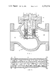
- FIG. 1 is a longitudinal cross sectional view of a typical high pressure control valve incorporating the energy dissipating trim assembly according to the invention.
- FIG. 2 is a cross sectional view of an annular disc or plate forming part of the restrictor assembly incorporated in the valve of FIG. 1.
- FIGS. 3 and 4 are top plan and bottom plan views respectively of the disc of FIG. 2.
- FIG. 5 is an enlarged partial cross sectional view of the energy dissipating trim assembly of the present invention incorporated in the valve of FIG. 1.
- FIGS. 6 and 7 are cross sectional views of the uppermost and lowermost elements respectively of the stacked disc assembly incorporated in the valve structure of FIG. 1.
- FIG. 8 is a cross sectional view of a disc element similar to that of FIG. 2, but modified for use in connection with a compressible fluid.
- FIGS. 9 and 10 are top plan and bottom plan views respectively of the disc element of FIG. 8.
- FIG. 11 is a cross sectional view of a disc element similar to that of FIG. 2, but modified for use within the disc stack in the areas thereof which are immediately adjacent the valve seat.
- FIGS. 12 and 13 are top and bottom plan views, respectively, of the disc element of FIG. 11.
- FIG. 1 there is illustrated a typical high pressure fluid control valve 10, comprising a valve body 12 provided with an outlet chamber 14 and an inlet chamber 16 separated by a web 18.
- the web 18 is provided with a vertical bore 22 for the reception of a shouldered, annular seat ring 20.
- the seat ring 20 is securely held in place in the web opening 22, and is provided with a suitable annular seal 13 in the area of its shoulder 23.
- the seat ring 20 is provided with a central fluid passage 24, and its upper rim is bevelled outward to provide an angled valve seat 26.
- a cylindrical stack 30 of annular discs Positioned above the seat ring 20 is a cylindrical stack 30 of annular discs, to be described in greater detail, over which is positioned a balancing cylinder 34.
- the upper portion of the valve body 12 is provided with a flange 37, to which is bolted or otherwise secured the flange 39 of a valve bonnet 38.
- the valve bonnet engages and secures in position the entire assembly of seat ring 20, disc stack 30 and balancing cylinder 34.
- it may be appropriate to provide a cylindrical retainer cage 44 which surrounds the disc stack 30 and is seated in recesses in the seat ring 20 and balancing cylinder 34.
- the retainer cage 44 is of substantially open construction, being provided with a plurality of vertical slots or openings 46 to accommodate the relatively unrestricted flow of fluid to and from the stack.
- the disc stack 30 and balancing cylinder 34 are provided with aligned cylindrical bores 32, 36, which closely and slideably receive a cylindrical valve plug 40.
- the valve plug 40 is connected to an operating rod or stem 42, which projects through a bore 43 in the valve bonnet and is connected to an appropriate automatic or manual actuating mechanism (not shown).
- the valve plug has a tapered, annular surface 41 at its lower end, which seats against the seat ring valve surface 46, when the plug is in its lowermost or closed position.
- the upper chamber 45 of the balancing cylinder is in communication with the high pressure or inlet side of the valve by reason of minor leakage past the seal 47.
- the high pressure prevailing in the chamber 45 serves to keep the valve closed.
- a relief port 15 provides communication between the chamber 45 and the outlet side of the valve to release the unbalanced high pressure fluid from the chamber.
- each of the discs 30a is formed of a metal suitable for the environment. Typically, this might be 410 stainless steel although the specific material of construction is not critical to the invention.
- a typical disc plate, for a "six inch" valve may have an overall diameter of close to seven and one half inches, and an internal diameter close to four and one half inches, it being understood that the dimensions herein given are typical for a given size of valve and would be adjusted appropriately for larger or smaller valves.
- the initial plate thickness typically may be on the order of 0.175 inch which, after machining to form axially projecting annular ribs, retains a basic web thickness of around 0.050 inch.
- the bottom face of the disc 30a is machined to provide a series of spaced annular ribs 51. These ribs are spaced appropriately along the central disc web 53, forming between them a series of annular recesses 54.
- the upper face of the disc 30a is provided with a series of radially spaced, upwardly projecting annular ribs 52, forming between them a series of upwardly facing annular grooves 55.
- the upwardly projecting ribs 52 are located intermediate, and approximately equally spaced from, the downwardly projecting ribs 51.
- the precise spacing of annular ribs may be varied to suit the conditions of service, so as to contribute to the avoidance of sufficiently large pressure drops at any stage to cause cavitation.
- the radial width of the annular grooves 54, 55 is significantly greater than the width of the ribs 51, 52 defining them. Accordingly, when a pair of discs 30a is arranged in vertically stacked relation, as shown in FIG. 5, the downwardly projecting annular ribs 51 of one disc project into the upwardly facing recesses 55 of the disc immediately below, and the upwardly projecting ribs 52 of a lower disc project into the downwardly facing recesses 54 of the disc above.
- the height of the ribs is substantially equal to the depth of the recesses, into which they project. The arrangement is such that, when discs are placed in axially stacked relation, the interfitting ribs and recesses form a series of annular passages 72-79 within the disc stack, substantially as shown in FIG. 5.
- the sets of annular ribs 51, 52 are provided with a series of radially aligned slots 61 (in the lower ribs 51) and 62 (in the upwardly projecting ribs 52).
- angular spacing X of adjacent radial slots will vary as a function of the size of the valve and the pressures and flow volumes to be dealt with, a typical six inch valve for high pressure service may utilize an angular slot spacing of three degrees, providing for 120 equally spaced radial rows of slots.
- the radial slotting of the discs will have the same spacing on opposite side
- the slots on opposite sides of the discs advantageously are offset through an angle equal to one half of the spacing angle between adjacent radial rows of slots.
- the lower slots will be offset one and one half degrees from the upper slots. This can be seen from comparison of FIGS. 3 and 4.
- the fluid entering into the restrictor assembly is confined between vertically adjacent plates as it flows generally radially from the outside to the inside (or vice versa in some cases), repetitively dividing and recombining as the individual flows enter the annular passages, meet an unslotted area of the next baffle rib, divide and flow circumferentially to a slotted opening on either side, combine and flow through the next slotted opening, etc.
- the flow area provided by the respective slots 61, 62 is significantly less than the flow area provided by the annular flow chambers 72-79.
- the annular ribs 51, 52 may be provided with slots approximately 0.062 inch wide and 0.055 inch deep.
- the annular flow passages 72-79 may have a depth of approximately 0.062 inch and a width of approximately 0.092 inch.
- the dimensions of the annular flow passages are achieved by providing for the annular recesses 54, 55 to be on the order of 0.235 inch in overall radial width, with a depth of 0.0622 inch.
- each recess there is, of course, a rib of approximately 0.050 width, defining two chambers of approximately 0.092 inch width.
- the annular flow passages thus have a flow area around 60% greater than the flow area of the radial slots 61, 62.
- the annular chambers carry a flow volume which is approximately one half that of the radial slots, inasmuch as the flow stream is divided upon passing through a radial slot, with approximately one half of the flow going in one direction, and one half going in the other.
- the radial slots 61, 62 need not extend for the full depth of the ribs 51, 52. Indeed, since the slots desirably are formed by a milling cutter or similar means arranged to form a row of slots across a full diameter of the disc, the slots desirably should terminate sufficiently above the bottoms of the recesses 54, 55 to avoid cutting into the bottom of the recess area within the normal tolerance range of the machining operation. In a typical case, the slots 51, 52 will be cut quite close to the bottoms of the recesses (e.g. 0.055 inch deep in a rib of 0.062 inch height), although it will be understood that shallower slots may be utilized where desirable or appropriate.
- the representative six inch valve heretofore referred to, it may be appropriate to provide a total of about six annular ribs on the bottom of a disc plate and five on the upper surface.
- Such a representative valve may have an axial stack of approximately fifteen of such discs, including the uppermost and lowermost disc elements.
- the upper and lower elements of the restrictor stack are shown to be formed by the balancing cylinder 34 and seat ring 20 respectively, with the lower surface 81 of the balancing cylinder and the upper surface 82 of the seat ring 20 being machined in the same manner as an upper surface of a disc 30a.
- each disc 30" is provided with a series of annular ribs 62", 64", 66", 68" spaced across the top surface thereof, and a series of annular ribs 61", 63", 65", 67", 69” spaced across the bottom surface of the disc 30" and radially offset from the ribs 62", 64", 66", 68" of the top surface.
- each rib 61"-69", inclusive includes a plurality of radial slots 51"-59", inclusive, respectively.
- one or more of the modified discs 30" are arranged at the lowermost levels of the disc stack, closely adjacent to the valve seat 26.
- the radial slots 51" to 59" define axis 70", 71" which form a 12° angle with respect to one another whereby there are thirty radial passages in the lower layers of the stack.
- the restrictor stack Although it may be possible to assemble the restrictor stack and hold the elements thereof together by clamping force alone, it is generally desirable to secure the parts together by brazing.
- the several discs may be coated with brazing powder and then heated in a high temperature furnace to fuse the stack. The final machining of the stack is performed after the brazing operation.
- the modified form of restrictor disc illustrated in FIGS. 8-10 of the drawings is in a form suitable for use in conjunction with compressible fluids, such as steam.
- compressible fluids such as steam.
- the construction of the valve for utilizing the modified restrictor disc is the same as that shown in FIG. 1, except that the illustrated valve is arranged for the flow of compressible fluid from the inside of the restrictor stack toward the outside. Since the incremental pressure drops of a compressible fluid will be accompanied by an increase in volume, it is desirable to progressively increase the size of the radial slots 61', 62' provided in the several rows of annular ribs 51', 52'.
- this may be readily accomplished by forming the radial rows of slots in two cuts, with the disc being rotated slightly between the first and second cuts.
- the width of the slots thus increases in proportion to the radius of the rib, accommodating expansion of the compressible fluid as it proceeds from the inside of the stack toward the outside. It may also be desirable in the disc modification of FIGS. 8-10 to progressively increase the radial spacing between adjacent annular ribs, from the inside to the outside of the disc, to provide for progressive enlargement of the annular flow passages, as well as the radial slots.
- the assembled disc stack is such as to provide for a relatively large plurality of individual, general radially progressing flow streams through the restrictor, with the flow streams alternately passing radially through a restricted orifice, then dividing and flowing circumferentially through an expansion chamber, then recombining and flowing radially through a restricted passage, etc.
- the combined effects of repetitive expansion and contraction, repetitive right angular changes of direction, and passage friction serve to effectively dissipate the high energy of the fluid, in dropping its pressure, to avoid excessive noise and cavitation effects. While the underlying principles of effecting pressure drop through multiple changes of direction, expansion and contraction, etc.
- valve structure of the present invention enables this to be achieved in a highly advantageous manner by providing for a series of annularly ribbed discs, which are machined to provide a series of radially aligned slots in the ribs.
- the ribs of one disc are interfitted with the ribs of an adjacent disc, so that a straight path from one radially aligned slot to another in a given disc is blocked by the interposition of an unslotted rib area from an adjacent disc.
- the individual discs could be provided with slots which are aligned on the top and bottom, with adjacent discs being angularly offset from each other to provide for the desired offset of radial slots between adjacent discs.
- it is mechanically superior, from the standpoint of strength of the discs, to machine the individual discs such that the slots on one surface are offset from slots on the opposite surface.
- the structure of the present invention enables a disc-type restrictor stack to be provided, which has some of the functional characteristics of the Willmann U.S. Pat. No. 973,328 and/or the Hayner U.S. Pat. No. 3,688,800, while at the same time providing for a greatly simlified, mechanically superior valve structure.
Landscapes
- Engineering & Computer Science (AREA)
- Mechanical Engineering (AREA)
- General Engineering & Computer Science (AREA)
- Details Of Valves (AREA)
Abstract
Description
Claims (8)
Priority Applications (1)
| Application Number | Priority Date | Filing Date | Title |
|---|---|---|---|
| US06/095,618 US4279274A (en) | 1977-09-29 | 1979-11-19 | Fluid control device with disc-type flow restrictor |
Applications Claiming Priority (2)
| Application Number | Priority Date | Filing Date | Title |
|---|---|---|---|
| US05/837,871 US4221037A (en) | 1977-09-29 | 1977-09-29 | Method for manufacturing a fluid control device with disc-type flow restrictor |
| US06/095,618 US4279274A (en) | 1977-09-29 | 1979-11-19 | Fluid control device with disc-type flow restrictor |
Related Parent Applications (1)
| Application Number | Title | Priority Date | Filing Date |
|---|---|---|---|
| US05/837,871 Division US4221037A (en) | 1977-09-29 | 1977-09-29 | Method for manufacturing a fluid control device with disc-type flow restrictor |
Publications (1)
| Publication Number | Publication Date |
|---|---|
| US4279274A true US4279274A (en) | 1981-07-21 |
Family
ID=26790401
Family Applications (1)
| Application Number | Title | Priority Date | Filing Date |
|---|---|---|---|
| US06/095,618 Expired - Lifetime US4279274A (en) | 1977-09-29 | 1979-11-19 | Fluid control device with disc-type flow restrictor |
Country Status (1)
| Country | Link |
|---|---|
| US (1) | US4279274A (en) |
Cited By (30)
| Publication number | Priority date | Publication date | Assignee | Title |
|---|---|---|---|---|
| US4593446A (en) * | 1984-04-18 | 1986-06-10 | Hayner Paul F | Method of manufacturing a fluid flow restrictor |
| US4938450A (en) * | 1989-05-31 | 1990-07-03 | Target Rock Corporation | Programmable pressure reducing apparatus for throttling fluids under high pressure |
| WO1993006400A1 (en) * | 1991-09-23 | 1993-04-01 | Vattenfall Utveckling Ab | Valve for regulating and/or shutting off the flow of liquid in a conduit |
| US5769122A (en) * | 1997-02-04 | 1998-06-23 | Fisher Controls International, Inc. | Fluid pressure reduction device |
| US5819803A (en) * | 1996-02-16 | 1998-10-13 | Lebo; Kim W. | Fluid pressure reduction device |
| EP0875705A3 (en) * | 1997-04-28 | 1999-08-11 | Welker Engineering Company | Flow diffuser and valve |
| US6026859A (en) * | 1998-01-28 | 2000-02-22 | Fisher Controls International, Inc. | Fluid pressure reduction device with linear flow characteristic |
| US6039076A (en) * | 1998-06-30 | 2000-03-21 | Copes-Vulcan, Inc. | High energy loss fluid control device |
| US6095196A (en) * | 1999-05-18 | 2000-08-01 | Fisher Controls International, Inc. | Tortuous path fluid pressure reduction device |
| US6161584A (en) * | 1998-06-30 | 2000-12-19 | Copes-Vulcan, Inc. | High energy loss fluid control device |
| US6250330B1 (en) | 1999-11-08 | 2001-06-26 | Welker Engineering Company | Diaphragm regulator with removable diffuser |
| US6289934B1 (en) | 1999-07-23 | 2001-09-18 | Welker Engineering Company | Flow diffuser |
| US6439267B2 (en) | 1999-07-23 | 2002-08-27 | Welker Engineering Company | Adjustable flow diffuser |
| US6615874B2 (en) | 2002-01-22 | 2003-09-09 | Flowserve Management Company | Stacked disk valve trim |
| US6715505B2 (en) | 2000-11-30 | 2004-04-06 | Dresser, Inc. | Steam pressure reducing and conditioning valve |
| US6718633B1 (en) * | 2003-03-14 | 2004-04-13 | Flowserve Management Company | Process for manufacturing valve trim assemblies |
| US6742773B2 (en) | 2000-11-30 | 2004-06-01 | Dresser, Inc. | Steam pressure reducing and conditioning valve |
| US6758232B2 (en) | 2000-11-30 | 2004-07-06 | Dresser, Inc. | Steam pressure reducing and conditioning system |
| US20050034770A1 (en) * | 2003-08-15 | 2005-02-17 | Stares James Albert | Fluid flow regulation |
| US20070017584A1 (en) * | 2005-07-19 | 2007-01-25 | Spx Corporation | Fluid trim apparatus and method |
| US7178782B1 (en) | 2003-05-23 | 2007-02-20 | The United States Of America As Represented By The Secretary Of The Navy | Quiet opening ball valve |
| US20070242560A1 (en) * | 2006-01-18 | 2007-10-18 | Yoshihiro Norikane | Microscopic flow passage structure, microscopic liquid droplet generating method, microscopic liquid droplet generating system, particles, and microcapsules |
| US7690400B2 (en) | 2005-02-28 | 2010-04-06 | Flowserve Management Company | Noise reducing fluid passageways for fluid control devices |
| US7802592B2 (en) | 2006-04-18 | 2010-09-28 | Fisher Controls International, Llc | Fluid pressure reduction devices |
| US20140339454A1 (en) * | 2013-05-16 | 2014-11-20 | Fisher Controls International Llc | Control valve trim cage having a plurality of anti-cavitation or noise abatement bars |
| US20150275612A1 (en) * | 2014-01-24 | 2015-10-01 | Cameron International Corporation | Low shear trim |
| US20170276252A1 (en) * | 2014-09-16 | 2017-09-28 | National Oilwell Varco, L.P. | Multistage stacked disc choke |
| CN109869522A (en) * | 2019-03-28 | 2019-06-11 | 吴忠中创自控阀有限公司 | A kind of labyrinth disk sleeve |
| US12428917B2 (en) | 2021-02-12 | 2025-09-30 | Drill Safe Systems Inc. | Drilling downhole regulating devices and related methods |
| US12612915B2 (en) | 2022-03-08 | 2026-04-28 | David Dyck | Intakes and gas separators for downhole pumps, and related apparatuses and methods |
Citations (5)
| Publication number | Priority date | Publication date | Assignee | Title |
|---|---|---|---|---|
| US973328A (en) * | 1910-04-02 | 1910-10-18 | Joseph Willmann | Emulsifier. |
| DE1008977B (en) * | 1955-02-15 | 1957-05-23 | Ewald Schlegel | Pressure reducing device with lockable variable or unchangeable throttle point for high pressure steam and supercritical pressure conditions and with a downstream intermediate pressure tank |
| US3856049A (en) * | 1971-09-23 | 1974-12-24 | Leslie Co | Multiple stage restrictor |
| US3917222A (en) * | 1974-02-25 | 1975-11-04 | Vacco Ind Inc | Sound suppressing gas flow control device |
| USRE29714E (en) | 1970-11-27 | 1978-08-01 | Sanders Associates, Inc. | Fluid flow restrictor |
-
1979
- 1979-11-19 US US06/095,618 patent/US4279274A/en not_active Expired - Lifetime
Patent Citations (5)
| Publication number | Priority date | Publication date | Assignee | Title |
|---|---|---|---|---|
| US973328A (en) * | 1910-04-02 | 1910-10-18 | Joseph Willmann | Emulsifier. |
| DE1008977B (en) * | 1955-02-15 | 1957-05-23 | Ewald Schlegel | Pressure reducing device with lockable variable or unchangeable throttle point for high pressure steam and supercritical pressure conditions and with a downstream intermediate pressure tank |
| USRE29714E (en) | 1970-11-27 | 1978-08-01 | Sanders Associates, Inc. | Fluid flow restrictor |
| US3856049A (en) * | 1971-09-23 | 1974-12-24 | Leslie Co | Multiple stage restrictor |
| US3917222A (en) * | 1974-02-25 | 1975-11-04 | Vacco Ind Inc | Sound suppressing gas flow control device |
Cited By (51)
| Publication number | Priority date | Publication date | Assignee | Title |
|---|---|---|---|---|
| US4593446A (en) * | 1984-04-18 | 1986-06-10 | Hayner Paul F | Method of manufacturing a fluid flow restrictor |
| US4938450A (en) * | 1989-05-31 | 1990-07-03 | Target Rock Corporation | Programmable pressure reducing apparatus for throttling fluids under high pressure |
| EP0401904A1 (en) * | 1989-05-31 | 1990-12-12 | Target Rock Corporation | Programmable pressure reducing apparatus for throttling fluids under high pressure |
| WO1993006400A1 (en) * | 1991-09-23 | 1993-04-01 | Vattenfall Utveckling Ab | Valve for regulating and/or shutting off the flow of liquid in a conduit |
| GB2275523A (en) * | 1991-09-23 | 1994-08-31 | Vattenfall Utveckling Ab | Valve for regulating and/or shutting off the flow of liquid in a conduit |
| GB2275523B (en) * | 1991-09-23 | 1995-06-14 | Vattenfall Utveckling Ab | Valve for regulating and/or shutting off the flow of liquid in a conduit |
| US5427147A (en) * | 1991-09-23 | 1995-06-27 | Vattenfall Utveckling Ab | Valve for regulating and/or shutting off the flow of liquid in a conduit |
| US5819803A (en) * | 1996-02-16 | 1998-10-13 | Lebo; Kim W. | Fluid pressure reduction device |
| US5769122A (en) * | 1997-02-04 | 1998-06-23 | Fisher Controls International, Inc. | Fluid pressure reduction device |
| US5941281A (en) * | 1997-02-04 | 1999-08-24 | Fisher Controls International, Inc. | Fluid pressure reduction device |
| EP0875705A3 (en) * | 1997-04-28 | 1999-08-11 | Welker Engineering Company | Flow diffuser and valve |
| US6026859A (en) * | 1998-01-28 | 2000-02-22 | Fisher Controls International, Inc. | Fluid pressure reduction device with linear flow characteristic |
| US6039076A (en) * | 1998-06-30 | 2000-03-21 | Copes-Vulcan, Inc. | High energy loss fluid control device |
| US6161584A (en) * | 1998-06-30 | 2000-12-19 | Copes-Vulcan, Inc. | High energy loss fluid control device |
| US6095196A (en) * | 1999-05-18 | 2000-08-01 | Fisher Controls International, Inc. | Tortuous path fluid pressure reduction device |
| US6289934B1 (en) | 1999-07-23 | 2001-09-18 | Welker Engineering Company | Flow diffuser |
| US6439267B2 (en) | 1999-07-23 | 2002-08-27 | Welker Engineering Company | Adjustable flow diffuser |
| US6250330B1 (en) | 1999-11-08 | 2001-06-26 | Welker Engineering Company | Diaphragm regulator with removable diffuser |
| US6715505B2 (en) | 2000-11-30 | 2004-04-06 | Dresser, Inc. | Steam pressure reducing and conditioning valve |
| US6742773B2 (en) | 2000-11-30 | 2004-06-01 | Dresser, Inc. | Steam pressure reducing and conditioning valve |
| US6758232B2 (en) | 2000-11-30 | 2004-07-06 | Dresser, Inc. | Steam pressure reducing and conditioning system |
| US6615874B2 (en) | 2002-01-22 | 2003-09-09 | Flowserve Management Company | Stacked disk valve trim |
| US6718633B1 (en) * | 2003-03-14 | 2004-04-13 | Flowserve Management Company | Process for manufacturing valve trim assemblies |
| US7178782B1 (en) | 2003-05-23 | 2007-02-20 | The United States Of America As Represented By The Secretary Of The Navy | Quiet opening ball valve |
| US7104281B2 (en) | 2003-08-15 | 2006-09-12 | Dresser, Inc. | Fluid flow regulation |
| US20050034770A1 (en) * | 2003-08-15 | 2005-02-17 | Stares James Albert | Fluid flow regulation |
| US8434525B2 (en) | 2005-02-28 | 2013-05-07 | Flowserve Management Company | Noise reducing fluid passageways for fluid flow control devices |
| US7690400B2 (en) | 2005-02-28 | 2010-04-06 | Flowserve Management Company | Noise reducing fluid passageways for fluid control devices |
| US20100175768A1 (en) * | 2005-02-28 | 2010-07-15 | Flowserve Management Company | Noise reducing fluid passageways for fluid flow control devices |
| US7886772B2 (en) | 2005-02-28 | 2011-02-15 | Flowserve Management Company | Noise reducing fluid passageways for fluid flow control devices |
| US20110100490A1 (en) * | 2005-02-28 | 2011-05-05 | Flowserve Management Company | Noise reducing fluid passageways for fluid flow control devices |
| US7195034B2 (en) | 2005-07-19 | 2007-03-27 | Spx Corporation | Fluid trim apparatus and method |
| US20070017584A1 (en) * | 2005-07-19 | 2007-01-25 | Spx Corporation | Fluid trim apparatus and method |
| US20070242560A1 (en) * | 2006-01-18 | 2007-10-18 | Yoshihiro Norikane | Microscopic flow passage structure, microscopic liquid droplet generating method, microscopic liquid droplet generating system, particles, and microcapsules |
| US8821006B2 (en) * | 2006-01-18 | 2014-09-02 | Ricoh Company, Ltd. | Microscopic flow passage structure, microscopic liquid droplet generating method, microscopic liquid droplet generating system, particles, and microcapsules |
| US7802592B2 (en) | 2006-04-18 | 2010-09-28 | Fisher Controls International, Llc | Fluid pressure reduction devices |
| US20100319799A1 (en) * | 2006-04-18 | 2010-12-23 | Mccarty Michael Wildie | Fluid pressure reduction devices |
| US8033300B2 (en) | 2006-04-18 | 2011-10-11 | Fisher Controls International, Llc | Fluid pressure reduction devices |
| US9518662B2 (en) * | 2013-05-16 | 2016-12-13 | Fisher Controls International Llc | Control valve trim cage having a plurality of anti-cavitation or noise abatement bars |
| US20140339454A1 (en) * | 2013-05-16 | 2014-11-20 | Fisher Controls International Llc | Control valve trim cage having a plurality of anti-cavitation or noise abatement bars |
| US9765589B2 (en) * | 2014-01-24 | 2017-09-19 | Cameron International Corporation | Low shear trim |
| US9624748B2 (en) | 2014-01-24 | 2017-04-18 | Cameron International Corporation | Low shear trim |
| US20150275612A1 (en) * | 2014-01-24 | 2015-10-01 | Cameron International Corporation | Low shear trim |
| US9856712B2 (en) | 2014-01-24 | 2018-01-02 | Cameron International Corporation | Low shear trim |
| US10024128B2 (en) | 2014-01-24 | 2018-07-17 | Cameron International Corporation | Low shear trim |
| US20170276252A1 (en) * | 2014-09-16 | 2017-09-28 | National Oilwell Varco, L.P. | Multistage stacked disc choke |
| US10655738B2 (en) * | 2014-09-16 | 2020-05-19 | National Oilwell Varco, L.P. | Multistage stacked disc choke |
| CN109869522A (en) * | 2019-03-28 | 2019-06-11 | 吴忠中创自控阀有限公司 | A kind of labyrinth disk sleeve |
| CN109869522B (en) * | 2019-03-28 | 2021-03-30 | 吴忠中创自控阀有限公司 | Labyrinth disc sleeve |
| US12428917B2 (en) | 2021-02-12 | 2025-09-30 | Drill Safe Systems Inc. | Drilling downhole regulating devices and related methods |
| US12612915B2 (en) | 2022-03-08 | 2026-04-28 | David Dyck | Intakes and gas separators for downhole pumps, and related apparatuses and methods |
Similar Documents
| Publication | Publication Date | Title |
|---|---|---|
| US4279274A (en) | Fluid control device with disc-type flow restrictor | |
| US4221037A (en) | Method for manufacturing a fluid control device with disc-type flow restrictor | |
| CA2526737C (en) | Control valve with vortex chambers | |
| US3780767A (en) | Control valve trim having high resistance vortex chamber passages | |
| US3856049A (en) | Multiple stage restrictor | |
| US4567915A (en) | Anti-cavitation low-noise control valve cage trim for high pressure reducing service in liquid or gaseous flow | |
| EP1165992B9 (en) | Fluid pressure reduction device | |
| US4398563A (en) | Multi-tube flow restrictor | |
| US4125129A (en) | Fixed and variable resistance fluid throttling apparatus | |
| US6161584A (en) | High energy loss fluid control device | |
| US4938450A (en) | Programmable pressure reducing apparatus for throttling fluids under high pressure | |
| US4679592A (en) | Valve seat design to reduce cavitation | |
| US3434500A (en) | Fluid pressure reducer | |
| US4674537A (en) | Straight-way & shut-off valve | |
| US4860993A (en) | Valve design to reduce cavitation and noise | |
| EP0727605B1 (en) | Fluid flow control device | |
| US6394134B1 (en) | Control valve trim for high-pressure fluid flow | |
| CA2319661C (en) | Fluid pressure reduction device with linear flow characteristic | |
| EP1266166B1 (en) | Fluid energy reduction device | |
| JPS5942186B2 (en) | Fluid flow control device | |
| US5732738A (en) | Valve trim | |
| US4018245A (en) | Perforated valve trim and method for producing the same | |
| EP1180627B1 (en) | High differential pressure regulating valve | |
| CN1010119B (en) | Multistage shunting laminated plate type anti-cavitation high-pressure-difference regulating valve | |
| GB2335054A (en) | High energy loss flow control devices |
Legal Events
| Date | Code | Title | Description |
|---|---|---|---|
| STCF | Information on status: patent grant |
Free format text: PATENTED CASE |
|
| AS | Assignment |
Owner name: BLAW-KNOX COMPANY Free format text: MERGER;ASSIGNORS:AETNA-STANDARD ENGINEERING COMPANY;BLAW-KNOX CONSTRUCTION EQUIPMENT, INC.,;BLAW-KNOX EQUIPMENT, INC.;AND OTHERS;REEL/FRAME:003926/0382 Effective date: 19781221 Owner name: WHITE CONSOLIDATED INDUSTRIES, INC. Free format text: MERGER;ASSIGNORS:BLAW-KNOX COMPANY;KELVINATOR, INC.;WHITE-WESTINGHOUSE CORPORATION;AND OTHERS;REEL/FRAME:003926/0372 Effective date: 19781221 |
|
| AS | Assignment |
Owner name: SANWA BUSINESS CREDIT CORPORATION, ONE SOUTH WACKE Free format text: SECURITY INTEREST;ASSIGNOR:ROADMASTER CORPORATION, A CORP. OF DE.;REEL/FRAME:004770/0976 Effective date: 19870810 Owner name: SANWA BUSINESS CREDIT CORPORATION,ILLINOIS Free format text: SECURITY INTEREST;ASSIGNOR:ROADMASTER CORPORATION, A CORP. OF DE.;REEL/FRAME:004770/0976 Effective date: 19870810 |
|
| AS | Assignment |
Owner name: SECURITY PACIFIC BUSINESS CREDIT INC., CHICAGO, IL Free format text: SECURITY INTEREST;ASSIGNOR:ROADMASTER CORPORATION;REEL/FRAME:005166/0753 Effective date: 19880831 |
|
| AS | Assignment |
Owner name: SECURITY PACIFIC BUSINESS CREDIT INC., ILLINOIS Free format text: SECURITY INTEREST;ASSIGNOR:ROADMASTER CORPORATION, A DE CORP.;REEL/FRAME:005461/0258 Effective date: 19890615 |
|
| AS | Assignment |
Owner name: SECURITY PACIFIC BUSINESS CREDIT INC., CHICAGO, IL Free format text: SECURITY INTEREST;ASSIGNOR:ROADMASTER CORPORATION, OLNEY, IL., A CORP. OF DE.;REEL/FRAME:005529/0370 Effective date: 19890615 |
|
| AS | Assignment |
Owner name: ROADMASTER CORPORATION, A DE CORP., ILLINOIS Free format text: SECURITY INTEREST;ASSIGNOR:SECURITY PACIFIC BUSINESS CREDIT INC., A DE CORP. CHICAGO, IL;REEL/FRAME:006135/0101 Effective date: 19920414 |
|
| AS | Assignment |
Owner name: CVI ACQUISITION CORPORATION, PENNSYLVANIA Free format text: ASSIGNMENT OF ASSIGNORS INTEREST;ASSIGNOR:WHITE CONSOLIDATED INDUSTRIES, INC. A DELAWARE CORPORATION;REEL/FRAME:007058/0883 Effective date: 19940624 |
|
| AS | Assignment |
Owner name: HELLER FINANCIAL INC., NEW YORK Free format text: SECURITY INTEREST;ASSIGNOR:CVI ACQUISITION CORPORATION;REEL/FRAME:007113/0243 Effective date: 19940624 |
|
| AS | Assignment |
Owner name: COPES-VULCAN, INC., PENNSYLVANIA Free format text: CHANGE OF NAME;ASSIGNOR:CVI ACQUISITION CORPORATION;REEL/FRAME:007476/0548 Effective date: 19940714 |