US4254972A - Stainless steel rotary joint - Google Patents
Stainless steel rotary joint Download PDFInfo
- Publication number
- US4254972A US4254972A US06/000,820 US82079A US4254972A US 4254972 A US4254972 A US 4254972A US 82079 A US82079 A US 82079A US 4254972 A US4254972 A US 4254972A
- Authority
- US
- United States
- Prior art keywords
- nipple
- casing
- seal
- guide
- rotary joint
- Prior art date
- Legal status (The legal status is an assumption and is not a legal conclusion. Google has not performed a legal analysis and makes no representation as to the accuracy of the status listed.)
- Expired - Lifetime
Links
- 229910001220 stainless steel Inorganic materials 0.000 title claims abstract description 8
- 239000010935 stainless steel Substances 0.000 title claims abstract description 8
- 210000002445 nipple Anatomy 0.000 claims abstract description 59
- 238000010276 construction Methods 0.000 claims abstract description 16
- 238000007789 sealing Methods 0.000 claims abstract description 16
- 239000002184 metal Substances 0.000 claims abstract description 14
- 229910052751 metal Inorganic materials 0.000 claims abstract description 14
- OKTJSMMVPCPJKN-UHFFFAOYSA-N Carbon Chemical compound [C] OKTJSMMVPCPJKN-UHFFFAOYSA-N 0.000 claims abstract description 7
- 239000010439 graphite Substances 0.000 claims abstract description 7
- 229910002804 graphite Inorganic materials 0.000 claims abstract description 7
- 230000006835 compression Effects 0.000 claims abstract description 4
- 238000007906 compression Methods 0.000 claims abstract description 4
- 238000005260 corrosion Methods 0.000 claims abstract description 4
- 230000007797 corrosion Effects 0.000 claims abstract description 4
- 238000004891 communication Methods 0.000 claims description 4
- 239000000463 material Substances 0.000 claims description 4
- 230000000295 complement effect Effects 0.000 claims description 2
- 239000007769 metal material Substances 0.000 claims 1
- 239000012530 fluid Substances 0.000 abstract description 9
- 239000011324 bead Substances 0.000 description 3
- 238000000034 method Methods 0.000 description 3
- 239000010425 asbestos Substances 0.000 description 2
- 238000007373 indentation Methods 0.000 description 2
- 238000009434 installation Methods 0.000 description 2
- 238000012423 maintenance Methods 0.000 description 2
- 230000004048 modification Effects 0.000 description 2
- 238000012986 modification Methods 0.000 description 2
- 230000009972 noncorrosive effect Effects 0.000 description 2
- 230000008569 process Effects 0.000 description 2
- 229910052895 riebeckite Inorganic materials 0.000 description 2
- 229910001018 Cast iron Inorganic materials 0.000 description 1
- 229910001208 Crucible steel Inorganic materials 0.000 description 1
- 230000002411 adverse Effects 0.000 description 1
- 229910000963 austenitic stainless steel Inorganic materials 0.000 description 1
- 230000004323 axial length Effects 0.000 description 1
- 229910052799 carbon Inorganic materials 0.000 description 1
- 238000001816 cooling Methods 0.000 description 1
- 230000008878 coupling Effects 0.000 description 1
- 238000010168 coupling process Methods 0.000 description 1
- 238000005859 coupling reaction Methods 0.000 description 1
- 238000001035 drying Methods 0.000 description 1
- 239000007789 gas Substances 0.000 description 1
- 239000007788 liquid Substances 0.000 description 1
- 239000003595 mist Substances 0.000 description 1
- 238000009428 plumbing Methods 0.000 description 1
- 238000012545 processing Methods 0.000 description 1
- 230000009467 reduction Effects 0.000 description 1
- 239000010959 steel Substances 0.000 description 1
- 231100000167 toxic agent Toxicity 0.000 description 1
- 239000003440 toxic substance Substances 0.000 description 1
- XLYOFNOQVPJJNP-UHFFFAOYSA-N water Substances O XLYOFNOQVPJJNP-UHFFFAOYSA-N 0.000 description 1
- 238000003466 welding Methods 0.000 description 1
Images
Classifications
-
- F—MECHANICAL ENGINEERING; LIGHTING; HEATING; WEAPONS; BLASTING
- F16—ENGINEERING ELEMENTS AND UNITS; GENERAL MEASURES FOR PRODUCING AND MAINTAINING EFFECTIVE FUNCTIONING OF MACHINES OR INSTALLATIONS; THERMAL INSULATION IN GENERAL
- F16L—PIPES; JOINTS OR FITTINGS FOR PIPES; SUPPORTS FOR PIPES, CABLES OR PROTECTIVE TUBING; MEANS FOR THERMAL INSULATION IN GENERAL
- F16L27/00—Adjustable joints; Joints allowing movement
- F16L27/02—Universal joints, i.e. with mechanical connection allowing angular movement or adjustment of the axes of the parts in any direction
- F16L27/023—Universal and rotating joints
-
- F—MECHANICAL ENGINEERING; LIGHTING; HEATING; WEAPONS; BLASTING
- F16—ENGINEERING ELEMENTS AND UNITS; GENERAL MEASURES FOR PRODUCING AND MAINTAINING EFFECTIVE FUNCTIONING OF MACHINES OR INSTALLATIONS; THERMAL INSULATION IN GENERAL
- F16L—PIPES; JOINTS OR FITTINGS FOR PIPES; SUPPORTS FOR PIPES, CABLES OR PROTECTIVE TUBING; MEANS FOR THERMAL INSULATION IN GENERAL
- F16L27/00—Adjustable joints; Joints allowing movement
- F16L27/08—Adjustable joints; Joints allowing movement allowing adjustment or movement only about the axis of one pipe
- F16L27/0804—Adjustable joints; Joints allowing movement allowing adjustment or movement only about the axis of one pipe the fluid passing axially from one joint element to another
- F16L27/0808—Adjustable joints; Joints allowing movement allowing adjustment or movement only about the axis of one pipe the fluid passing axially from one joint element to another the joint elements extending coaxially for some distance from their point of separation
- F16L27/0812—Adjustable joints; Joints allowing movement allowing adjustment or movement only about the axis of one pipe the fluid passing axially from one joint element to another the joint elements extending coaxially for some distance from their point of separation with slide bearings
- F16L27/082—Adjustable joints; Joints allowing movement allowing adjustment or movement only about the axis of one pipe the fluid passing axially from one joint element to another the joint elements extending coaxially for some distance from their point of separation with slide bearings having axial sealing
-
- F—MECHANICAL ENGINEERING; LIGHTING; HEATING; WEAPONS; BLASTING
- F16—ENGINEERING ELEMENTS AND UNITS; GENERAL MEASURES FOR PRODUCING AND MAINTAINING EFFECTIVE FUNCTIONING OF MACHINES OR INSTALLATIONS; THERMAL INSULATION IN GENERAL
- F16L—PIPES; JOINTS OR FITTINGS FOR PIPES; SUPPORTS FOR PIPES, CABLES OR PROTECTIVE TUBING; MEANS FOR THERMAL INSULATION IN GENERAL
- F16L39/00—Joints or fittings for double-walled or multi-channel pipes or pipe assemblies
- F16L39/04—Joints or fittings for double-walled or multi-channel pipes or pipe assemblies allowing adjustment or movement
Definitions
- the invention pertains to rotary joints for transmitting fluids between stationary conduits and rotating members.
- Rotary joints capable of conducting fluids under superatmospheric or subatmospheric pressures have long been used to interconnect stationary conduits with rotary members, such as drying or cooling drums.
- Such rotary joints are widely used in the paper making and web processing arts, and typical rotary joint constructions are shown in the assignee's U.S. Pat. Nos. 2,477,762; 2,497,183 and 3,265,411.
- Such rotary joints normally consist of a cast body or casing having a nipple coaxially rotatably mounted within the body wherein an exterior end of the nipple is mounted upon the rotating drum, and the nipple end within body is provided with means for establishing a rotatable fluid tight relationship with the body.
- seal and bearing arrangements are utilized, and it is common to include syphon pipe structure within the nipple wherein, in a steam heat installation, steam may introduce into the drum, and the condensate removed therefrom, through a single rotary joint.
- a further object of the invention is to provide a lightweight rotary joint of relatively inexpensive construction wherein an extended operable life is achieved and which economically permits complete replacement of the entire joint after the effective seal life has been depleted.
- An additional object of the invention is to provide a lightweight rotary joint utilizing seals capable of efficient operation under elevated temperatures wherein effective engagement between the seals is maintained during wearing of the seals, and indicia indicate seal depletion and the necessity of rotary joint replacement.
- the rotary joint of the invention utilizes a sheet metal casing or body formed of stainless steel, and one end of the body is provided with an opening through which a tubular nipple extends for attachment to the rotary member to be serviced by the joint.
- the opposite casing end is provided with a threaded adapter to which a fluid conduit, of conduits, may be attached.
- the nipple is supported on a pair of annular graphite guides, a guide being disposed adjacent each casing end and sealed thereto by an O-ring.
- the casing is of a substantially cylindrical construction, and a stop rod lug may be welded thereto for receiving a stop rod which partially supports the casing and prevents axial or rotational movement thereof.
- the conduit adapter threaded to the casing adapter may include a syphon pipe port, for accommodating either a stationary or rotating syphon.
- the ends of the casing are defined by the same sheet metal assembly forming the sidewall, and the preferred method of construction comprises forming the casing from the two cup-like components by drawing, and welding the cups' open ends in an abutting relationship to define the hollow casing configuration.
- the rotary joint is assembled prior to the casing being welded, and the assembly process, and construction, renders the rotary joint tamper-proof.
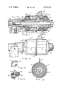
- FIG. 1 is an elevational, diametrical, sectional view of a rotary joint constructed in accord with the invention
- FIG. 2 is an elevational view of the rotary joint of FIG. 1,
- FIG. 3 is an elevational, sectional view as taken along Section III--III of FIG. 1,
- FIG. 4 is a partial, elevational, sectional, reduced scale view of a through flow fluid connector
- FIG. 5 is a detailed, sectional, reduced scale view of a rotary syphon adapter as used with the rotary joint of the invention.
- the rotary joint of the invention includes a casing 10 of an elongated generally cylindrical configuration which is formed of a pair of substantially identical sheet metal cup portions 12 and 14, which are usually formed by a metal drawing process.
- the cup portions each include a cylindrical sidewall 16 terminating in an outwardly deformed edge which are abutted and welded at bead 18.
- the end wall 20 is provided with a central opening 22, and the end wall 24 is formed with a coaxial opening 26, an an exteriorly threaded tubular adapter 28 is coaxially affixed to the end wall 24 by weld bead 30.
- the threads 32 are conventional pipe threads.
- the casing 10 is formed of an austenitic stainless steel, such as AISI No. 304L, and such metal is highly resistant to corrosion.
- a stop rod lug 34 may be welded to the casing sidewall, and the lug includes an opening for receiving the threaded end of a stop rod, not shown, which is fixed to stationary structure and provides a support for the rotary joint and prevents axial movement and rotation thereof.
- a pair of annular guides 36 and 38 are located within the casing chamber 40.
- Guide 36 is disposed adjacent casing end 20 and includes a cylindrical bore 42, a flat radial seal surface 46, and an annular groove 48 receiving O-ring 50 which sealingly engages the sidewall 16.
- Guide 36 is radially grooved at 52 and an indentation 54 defined in end wall 20 is received within groove 52 which functions as a key to prevent rotation of guide 36 within the casing.
- Guide 38 adjacent casing end wall 24 is of an identical construction, including cylindrical bore 42' and radial surface 46', and is sealed to the casing by O-ring 50'. Likewise, groove 52' and indentation 54' lock the guide 38 against rotation.
- a tubular nipple 56 includes a inner end 58 located within the casing chamber 40 and an outer end 60 which extends through the casing opening 22. Outer end 60 is formed with pipe threads, or other attachment means, well known in the art, whereby the nipple may be coaxially affixed to a rotating dryer drum or the like, not shown, wherein the nipple communicates with the drum interior and rotates with the drum.
- An annular nipple seal 62 is defined upon the nipple inner end 58 and the nipple seal includes a spherical convex sealing surface 64 having a center lying upon the nipple axis.
- the nipple diameter is such as to be closely received within the bores of the guides 36 and 38 and the nipple is rotatably supported within the casing 10 by the guides.
- An annular seal ring 66 is interposed between the nipple seal 62 and guide 36, and the seal ring includes a spherical concave sealing surface 68 engaging nipple seal surface 64 in a complementary manner, and the flat radial seal ring surface 70 sealingly engages guide surface 46.
- An annular thrust plate 72 engaging guide surface 46' engages one end of compression spring 74 while the other spring end bears against nipple seal 62 to bias the nipple toward the right, FIG. 1. This biasing force will maintain an effective sealing between surfaces 64 and 68, and 70 and 46.
- the guides 36 and 38, and the annular seal ring 66 are formed of a long wearing nonasbestos material such as graphite, and the seal ring will provide a long effective seal life as it gradually wears.
- An annular indicia groove 76 is defined upon the exterior surface of the nipple 56, and when the seal ring 66 is significantly worn its axial dimension will be substantially reduced with respect to that shown in FIG. 1 and the groove 76 will become visible adjacent opening 22, and maintenance personnel will appreciate that the rotary joint should be replaced.
- Rotary joints as used with rotating heat exchanging drums, are basically of three types.
- the through flow type permits a single fluid to be handled by the joint, and in such instance a fitting 78 such as shown in FIG. 4 is mounted upon the threaded adapter 28 whereby a conduit may be attached to the adapter in communication with the interior of the nipple. If the rotary joint is to be used with a steam heated dryer drum and a stationary condensate syphon is employed, the fitting 80 shown in FIG. 1 is utilized.
- Fitting 80 threads upon adapter 28 and includes the steam inlet port 82 affixed to a steam supply conduit, not shown, and the staiffy syphon pipe 84 extends through the nipple and may be threaded into the fitting in communication with the syphon discharge port 86.
- a rotary syphon fitting 88 includes the steam inlet port 90 and the rotating syphon conduit 92 is rotatably supported on the fitting 88 by seal 94, whereby the end of the syphon pipe communicates with the syphon discharge port 96.
- the casing adapter 28 permits a variety of plumbing fittings to be readily attached to the rotary joint, and it will be appreciated that the adapter may either be externally or internally threaded, or could constitute a bolt-on flange, or other conventional fluid coupling construction.
- the sheet metal construction of the rotary joint substantially reduces the weight of the joint as compared with cast casings for joints of equivalent capacity. Also, the sheet metal construction is aesthetically "clean".
- the carbon-to-carbon seal assembly provided with the graphite guides and seal ring assures a long effective seal life, and as the casing assembly is achieved by weld bead 30 the joint is tamper-proof and modification by unauthorized personnel is prevented.
Landscapes
- Engineering & Computer Science (AREA)
- General Engineering & Computer Science (AREA)
- Mechanical Engineering (AREA)
- Joints Allowing Movement (AREA)
- Quick-Acting Or Multi-Walled Pipe Joints (AREA)
- Mechanical Sealing (AREA)
Abstract
The invention pertains to a rotary joint for transmitting fluids to or from rotating members characterized by its corrosion resistance, lightweight and tamper-proof construction. The joint includes a sheet metal stainless steel casing in which a tubular nipple is rotatably mounted upon graphite guide bearings. A nipple seal defined on the nipple engages an annular seal ring interposed between the nipple seal and a guide, and a compression spring biases the nipple and nipple seal in a direction to maintain a sealing engagement between the seal surfaces. A threaded adapter located at an end of the casing permits fluid conducting conduits to communicate with the nipple.
Description
The invention pertains to rotary joints for transmitting fluids between stationary conduits and rotating members.
Rotary joints capable of conducting fluids under superatmospheric or subatmospheric pressures have long been used to interconnect stationary conduits with rotary members, such as drying or cooling drums. Such rotary joints are widely used in the paper making and web processing arts, and typical rotary joint constructions are shown in the assignee's U.S. Pat. Nos. 2,477,762; 2,497,183 and 3,265,411. Such rotary joints normally consist of a cast body or casing having a nipple coaxially rotatably mounted within the body wherein an exterior end of the nipple is mounted upon the rotating drum, and the nipple end within body is provided with means for establishing a rotatable fluid tight relationship with the body. Various types of seal and bearing arrangements are utilized, and it is common to include syphon pipe structure within the nipple wherein, in a steam heat installation, steam may introduce into the drum, and the condensate removed therefrom, through a single rotary joint.
Conventional rotary joints of the above described type are usually assembled by the use of bolts, and heads and wear plates are removably affixed to the body. This assembly permits replacement of the joint bearings and seals, and while such seal replacement permits regular maintenance, it has been the practice of rotary joint owners to occasionally replace worn original seals with seals of lesser quality than originally provided subjecting the original rotary joint manufacturer to undeserved liability.
Known rotary joints often use asbestos gasket materials, and such use of asbestos subjects the manufacturer to further product liability under the requirements of the Toxic Substance Control Act.
The general use of cast iron and steel with conventional rotary joints results in significant weight, and such weight has an adverse affect upon seal life. Also, in some industrial environments the rotary joint is subjected to highly corrosive liquids, mist and gases, and the cast body is subject to rapid corrosion, especially under the elevated temperatures achieved when the joint is conducting steam or hot water.
While stainless steel has long been recognized for its noncorrosive characteristics, and as cast stainless steel has been used by the assignee in the construction of its rotary joints, to the inventors' knowledge a rotary joint has not herefore been constructed of sheet metal stainless wherein the lightweight advantages of such a construction have been fully utilized. Stainless steel sheet metal casings have been employed in the construction of steam traps, as shown in U.S. Pat. No. 3,892,256, but such steam traps do not incorporate rotative bearing and seal structure, and are not subjected to the stresses and wear imposed upon a rotary joint.
It is an object of the invention to provide a rotary joint employing a light weight sheet metal casing of noncorrosive material which is of a tamper-proof construction and wherein extended seal life is achieved.
A further object of the invention is to provide a lightweight rotary joint of relatively inexpensive construction wherein an extended operable life is achieved and which economically permits complete replacement of the entire joint after the effective seal life has been depleted.
An additional object of the invention is to provide a lightweight rotary joint utilizing seals capable of efficient operation under elevated temperatures wherein effective engagement between the seals is maintained during wearing of the seals, and indicia indicate seal depletion and the necessity of rotary joint replacement.
The rotary joint of the invention utilizes a sheet metal casing or body formed of stainless steel, and one end of the body is provided with an opening through which a tubular nipple extends for attachment to the rotary member to be serviced by the joint. The opposite casing end is provided with a threaded adapter to which a fluid conduit, of conduits, may be attached. Internally, the nipple is supported on a pair of annular graphite guides, a guide being disposed adjacent each casing end and sealed thereto by an O-ring. An annular nipple seal defined on the nipple, and fixed thereto, engages a graphite seal ring and a compression spring engaging the nipple seal biases the nipple in a direction to maintain a sealing engagement between the nipple seal, seal ring and the adjacent guide.
The casing is of a substantially cylindrical construction, and a stop rod lug may be welded thereto for receiving a stop rod which partially supports the casing and prevents axial or rotational movement thereof. The conduit adapter threaded to the casing adapter may include a syphon pipe port, for accommodating either a stationary or rotating syphon.
The ends of the casing are defined by the same sheet metal assembly forming the sidewall, and the preferred method of construction comprises forming the casing from the two cup-like components by drawing, and welding the cups' open ends in an abutting relationship to define the hollow casing configuration. The rotary joint is assembled prior to the casing being welded, and the assembly process, and construction, renders the rotary joint tamper-proof.
The aforementioned objects and advantages of the invention will be appreciated from the following description and accompanying drawings wherein:
FIG. 1 is an elevational, diametrical, sectional view of a rotary joint constructed in accord with the invention,
FIG. 2 is an elevational view of the rotary joint of FIG. 1,
FIG. 3 is an elevational, sectional view as taken along Section III--III of FIG. 1,
FIG. 4 is a partial, elevational, sectional, reduced scale view of a through flow fluid connector, and
FIG. 5 is a detailed, sectional, reduced scale view of a rotary syphon adapter as used with the rotary joint of the invention.
The rotary joint of the invention includes a casing 10 of an elongated generally cylindrical configuration which is formed of a pair of substantially identical sheet metal cup portions 12 and 14, which are usually formed by a metal drawing process. The cup portions each include a cylindrical sidewall 16 terminating in an outwardly deformed edge which are abutted and welded at bead 18. The end wall 20 is provided with a central opening 22, and the end wall 24 is formed with a coaxial opening 26, an an exteriorly threaded tubular adapter 28 is coaxially affixed to the end wall 24 by weld bead 30. The threads 32 are conventional pipe threads.
Preferably, the casing 10 is formed of an austenitic stainless steel, such as AISI No. 304L, and such metal is highly resistant to corrosion.
A stop rod lug 34 may be welded to the casing sidewall, and the lug includes an opening for receiving the threaded end of a stop rod, not shown, which is fixed to stationary structure and provides a support for the rotary joint and prevents axial movement and rotation thereof.
A pair of annular guides 36 and 38 are located within the casing chamber 40. Guide 36 is disposed adjacent casing end 20 and includes a cylindrical bore 42, a flat radial seal surface 46, and an annular groove 48 receiving O-ring 50 which sealingly engages the sidewall 16. Guide 36 is radially grooved at 52 and an indentation 54 defined in end wall 20 is received within groove 52 which functions as a key to prevent rotation of guide 36 within the casing. Guide 38 adjacent casing end wall 24 is of an identical construction, including cylindrical bore 42' and radial surface 46', and is sealed to the casing by O-ring 50'. Likewise, groove 52' and indentation 54' lock the guide 38 against rotation.
A tubular nipple 56 includes a inner end 58 located within the casing chamber 40 and an outer end 60 which extends through the casing opening 22. Outer end 60 is formed with pipe threads, or other attachment means, well known in the art, whereby the nipple may be coaxially affixed to a rotating dryer drum or the like, not shown, wherein the nipple communicates with the drum interior and rotates with the drum.
An annular nipple seal 62 is defined upon the nipple inner end 58 and the nipple seal includes a spherical convex sealing surface 64 having a center lying upon the nipple axis. The nipple diameter is such as to be closely received within the bores of the guides 36 and 38 and the nipple is rotatably supported within the casing 10 by the guides.
An annular seal ring 66 is interposed between the nipple seal 62 and guide 36, and the seal ring includes a spherical concave sealing surface 68 engaging nipple seal surface 64 in a complementary manner, and the flat radial seal ring surface 70 sealingly engages guide surface 46.
An annular thrust plate 72 engaging guide surface 46' engages one end of compression spring 74 while the other spring end bears against nipple seal 62 to bias the nipple toward the right, FIG. 1. This biasing force will maintain an effective sealing between surfaces 64 and 68, and 70 and 46.
Preferably, the guides 36 and 38, and the annular seal ring 66, are formed of a long wearing nonasbestos material such as graphite, and the seal ring will provide a long effective seal life as it gradually wears. An annular indicia groove 76 is defined upon the exterior surface of the nipple 56, and when the seal ring 66 is significantly worn its axial dimension will be substantially reduced with respect to that shown in FIG. 1 and the groove 76 will become visible adjacent opening 22, and maintenance personnel will appreciate that the rotary joint should be replaced.
Rotary joints, as used with rotating heat exchanging drums, are basically of three types. The through flow type permits a single fluid to be handled by the joint, and in such instance a fitting 78 such as shown in FIG. 4 is mounted upon the threaded adapter 28 whereby a conduit may be attached to the adapter in communication with the interior of the nipple. If the rotary joint is to be used with a steam heated dryer drum and a stationary condensate syphon is employed, the fitting 80 shown in FIG. 1 is utilized. Fitting 80 threads upon adapter 28 and includes the steam inlet port 82 affixed to a steam supply conduit, not shown, and the staionary syphon pipe 84 extends through the nipple and may be threaded into the fitting in communication with the syphon discharge port 86.
In the third rotary joint installation as shown in FIG. 5, a rotary syphon fitting 88 includes the steam inlet port 90 and the rotating syphon conduit 92 is rotatably supported on the fitting 88 by seal 94, whereby the end of the syphon pipe communicates with the syphon discharge port 96.
Accordingly, it will be appreciated that the casing adapter 28 permits a variety of plumbing fittings to be readily attached to the rotary joint, and it will be appreciated that the adapter may either be externally or internally threaded, or could constitute a bolt-on flange, or other conventional fluid coupling construction.
The sheet metal construction of the rotary joint substantially reduces the weight of the joint as compared with cast casings for joints of equivalent capacity. Also, the sheet metal construction is aesthetically "clean". The carbon-to-carbon seal assembly provided with the graphite guides and seal ring assures a long effective seal life, and as the casing assembly is achieved by weld bead 30 the joint is tamper-proof and modification by unauthorized personnel is prevented.
The resultant reduction in weight significantly adds to the bearing life, and as the nipple is axially supported by the guides 36 and 38 at spaced locations and for significant axial lengths lateral forces on the nipple are effectively distributed.
It is appreciated that various modifications to the invention may be apparent to those skilled in the art without departing from the spirit and scope of the invention.
Claims (8)
1. A rotary joint characterized by its light weight, long life and tamper-proof construction, comprising in combination, an elongated sheet metal casing having an axis, a side wall and first and second ends defining a chamber, said casing being formed of sheet metal portions welded together and said ends being integrally formed of the sheet metal material of said side wall and extending from said side wall toward said axis, an elongated tubular nipple having an outer end extending from said casing first end and an inner end within said chamber and coaxial with said casing, attachment means defined on said nipple outer end, adapter attachment means defined on said casing second end in communication with said nipple, an annular nipple seal sealingly fixed on said nipple inner end having a sealing surface facing said casing first end, an annular first guide within said chamber adjacent said first end, sealing means defined on said first guide sealing said guide to said casing, an annular seal ring located intermediate said nipple seal and said guide sealingly engaging said nipple seal and guide, an annular second guide within said chamber adjacent said second end, sealing means defined on said second guide sealing said second guide to said casing, said guides including central cylindrical bores rotatably supporting said nipple inner end and maintained in assembly upon said nipple by said casing ends, and a compression spring circumscribing said nipple inner end located between said second guide and nipple seal biasing said nipple seal toward said seal ring and first guide to maintain sealing engagement of said seal ring with said nipple seal and said first guide.
2. In a rotary joint as in claim 1 wherein said casing is formed of stainless steel.
3. In a rotary joint as in claim 1, a stop rod support lug affixed to said casing radially extending therefrom, and a stop rod receiving opening defined in said lug.
4. In a rotary joint as in claim 1, wherein said adapter attachment comprises a tubular member coaxially welded to said casing second end, and pipe threads defined on said member.
5. In a rotary joint as in claim 1 wherein said seal ring is formed of a non-metallic wear resistant material.
6. In a rotary joint as in claim 5 wherein said seal ring and first and second guides are formed of graphite.
7. In a rotary joint as in claim 1, said nipple seal sealing surface constituting a convex spherical segment having a center lying on said casing axis, and a complementary concave spherical surface defined on said seal ring engaging said sealing surface.
8. A rotary joint characterized by its light weight, long life, resistance to corrosion and tamper-proof construction comprising, in combination, a stainless steel sheet metal casing having an axis, a cylindrical side wall, and first and second ends integral with said wall and extending from said side wall toward said axis defining a chamber, said casing being defined by a pair of cup shaped portions welded together at a circular joint upon said side wall, a tubular nipple coaxially received within said casing having an inner end within said chamber and an outer end extending through said first end, attachment means defined on said nipple outer end, adapter attachment means defined on said casing second end in communication with said nipple, an annular nipple seal sealingly fixed on said nipple end having a convex sealing surface, an annular graphite guide adjacent each casing end maintained within said casing by said casing ends and sealed to said casing and rotatably supporting said nipple, sealing means defined on said guides engaging said casing, an annular seal ring interposed between said nipple seal and the guide adjacent said casing first end, and spring means biasing said nipple seal toward said seal ring and into sealing engagement therewith maintaining a sealed relationship between said nipple seal, seal ring and said guide adjacent said first end.
Priority Applications (9)
| Application Number | Priority Date | Filing Date | Title |
|---|---|---|---|
| US06/000,820 US4254972A (en) | 1979-01-04 | 1979-01-04 | Stainless steel rotary joint |
| CA000338340A CA1140356A (en) | 1979-01-04 | 1979-10-24 | Stainless steel rotary joint |
| ZA00795820A ZA795820B (en) | 1979-01-04 | 1979-10-30 | Stainless steel rotary joint |
| GB7938432A GB2038969B (en) | 1979-01-04 | 1979-11-06 | Stainless steel rotary joint |
| JP14532579A JPS5594089A (en) | 1979-01-04 | 1979-11-09 | Rotary joint of stainless steel |
| MX180106A MX149358A (en) | 1979-01-04 | 1979-11-21 | IMPROVEMENTS IN CONNECTOR DEVICE TO PLACE BETWEEN A STATIONARY DUCT AND ROTATING MEMBERS |
| BR7907789A BR7907789A (en) | 1979-01-04 | 1979-11-29 | ROTARY JOINT |
| FR7930237A FR2445924B1 (en) | 1979-01-04 | 1979-12-10 | ARTICULATED PIPE CONNECTION |
| DE2949693A DE2949693C2 (en) | 1979-01-04 | 1979-12-11 | Slewing ring |
Applications Claiming Priority (1)
| Application Number | Priority Date | Filing Date | Title |
|---|---|---|---|
| US06/000,820 US4254972A (en) | 1979-01-04 | 1979-01-04 | Stainless steel rotary joint |
Publications (1)
| Publication Number | Publication Date |
|---|---|
| US4254972A true US4254972A (en) | 1981-03-10 |
Family
ID=21693149
Family Applications (1)
| Application Number | Title | Priority Date | Filing Date |
|---|---|---|---|
| US06/000,820 Expired - Lifetime US4254972A (en) | 1979-01-04 | 1979-01-04 | Stainless steel rotary joint |
Country Status (9)
| Country | Link |
|---|---|
| US (1) | US4254972A (en) |
| JP (1) | JPS5594089A (en) |
| BR (1) | BR7907789A (en) |
| CA (1) | CA1140356A (en) |
| DE (1) | DE2949693C2 (en) |
| FR (1) | FR2445924B1 (en) |
| GB (1) | GB2038969B (en) |
| MX (1) | MX149358A (en) |
| ZA (1) | ZA795820B (en) |
Cited By (20)
| Publication number | Priority date | Publication date | Assignee | Title |
|---|---|---|---|---|
| US4606560A (en) * | 1985-12-23 | 1986-08-19 | Aeroquip Corporation | Thrust bearing rotary joint |
| US4635969A (en) * | 1985-05-31 | 1987-01-13 | The Johnson Corporation | Rotary joint with balanced seals |
| US4867212A (en) * | 1987-06-19 | 1989-09-19 | Dragerwerk Aktiengesellschaft | Safety arrangement for filling and emptying an anesthetic vaporizer |
| US5110162A (en) * | 1991-02-28 | 1992-05-05 | The Johnson Corporation | Anti-corrosive rotary joint |
| US5165734A (en) * | 1991-09-03 | 1992-11-24 | Smith Precision Products Company | Conduit swivel connector |
| US5209526A (en) * | 1991-09-17 | 1993-05-11 | Glastonbury Engineering Pty. Limited | Rotary joint assembly |
| US5303959A (en) * | 1993-02-01 | 1994-04-19 | The Johnson Corporation | High speed rotary joint |
| US6290583B1 (en) * | 1997-09-10 | 2001-09-18 | Ebara Corporation | Apparatus for holding workpiece |
| WO2003089832A1 (en) * | 2002-04-19 | 2003-10-30 | S.D. Warren Services Company | Rotary joints |
| US20060082143A1 (en) * | 2004-09-14 | 2006-04-20 | Pospisil Mark G | Rotary union for directing a heat exchange fluid |
| US20060162414A1 (en) * | 2002-04-16 | 2006-07-27 | Bartlett Michael Charles R | Arrangement for cooling a roll |
| ITMI20081218A1 (en) * | 2008-07-02 | 2010-01-03 | Fluiten Italia | ROTARY JOINT |
| US20110037259A1 (en) * | 2009-08-06 | 2011-02-17 | Centrotherm Thermal Solutions Gmbh & Co. Kg | Connector for gas or liquid lines and use thereof |
| US20160041359A1 (en) * | 2014-08-08 | 2016-02-11 | Servomex Group Limited | Alignment Device and Transmitter/Receiver System with Two Angular Degrees of Freedom |
| CN109654317A (en) * | 2018-08-22 | 2019-04-19 | 宁波乐惠国际工程装备股份有限公司 | A kind of bridging tube assembly |
| CN114630981A (en) * | 2019-11-15 | 2022-06-14 | 当特詹森有限责任公司 | Rotary union shroud with assembly gauge and seal wear indicator |
| US20250224053A1 (en) * | 2024-01-05 | 2025-07-10 | Hanwit Precision Industries Ltd. | Floating connector for liquid cooling device |
| US20250224062A1 (en) * | 2024-01-05 | 2025-07-10 | Hanwit Precision Industries Ltd. | Floating adapter module |
| US12372179B1 (en) * | 2024-07-29 | 2025-07-29 | Fositek Corporation | Floating joint and retainer connection device with friction reduction structure |
| US12486932B1 (en) * | 2024-07-29 | 2025-12-02 | Fositek Corporation | Floating joint and retainer connection device with pressure relief structure |
Citations (11)
| Publication number | Priority date | Publication date | Assignee | Title |
|---|---|---|---|---|
| US1529994A (en) * | 1921-03-23 | 1925-03-17 | Ellis Drier & Elevator Company | Pipe connection |
| US2305725A (en) * | 1939-06-15 | 1942-12-22 | Rotary Seal Company | Seal |
| US2477762A (en) * | 1946-03-08 | 1949-08-02 | Johnson Corp | Nipple assembly |
| US2497183A (en) * | 1947-04-30 | 1950-02-14 | Johnson Corp | Swing joint |
| US2733080A (en) * | 1956-01-31 | Sand eliminator bearing for a sprinkler | ||
| US2791449A (en) * | 1953-01-19 | 1957-05-07 | Johnson Corp | Rotary self-supporting pressure joint |
| US2805086A (en) * | 1952-10-30 | 1957-09-03 | Rotherm Engineering Company In | Liquid-tight and gas-tight rotating tubular joints |
| US2836439A (en) * | 1956-04-23 | 1958-05-27 | Francis N Bard | Swivel joint with sealing means permitting pivotal movement |
| US3265411A (en) * | 1964-03-23 | 1966-08-09 | Johnson Corp | Syphon support |
| US3484853A (en) * | 1968-05-13 | 1969-12-16 | Takeda Seisakusho Kk | Rotary joint union for heavy duty |
| US3892256A (en) * | 1973-11-27 | 1975-07-01 | Armstrong Machine Works | Inverted bucket steam trap |
Family Cites Families (1)
| Publication number | Priority date | Publication date | Assignee | Title |
|---|---|---|---|---|
| DE939186C (en) * | 1953-01-19 | 1956-02-16 | Johnson Corp | Device for connecting the feed line of a pressurized flow medium with rotating machine parts |
-
1979
- 1979-01-04 US US06/000,820 patent/US4254972A/en not_active Expired - Lifetime
- 1979-10-24 CA CA000338340A patent/CA1140356A/en not_active Expired
- 1979-10-30 ZA ZA00795820A patent/ZA795820B/en unknown
- 1979-11-06 GB GB7938432A patent/GB2038969B/en not_active Expired
- 1979-11-09 JP JP14532579A patent/JPS5594089A/en active Pending
- 1979-11-21 MX MX180106A patent/MX149358A/en unknown
- 1979-11-29 BR BR7907789A patent/BR7907789A/en not_active IP Right Cessation
- 1979-12-10 FR FR7930237A patent/FR2445924B1/en not_active Expired
- 1979-12-11 DE DE2949693A patent/DE2949693C2/en not_active Expired
Patent Citations (11)
| Publication number | Priority date | Publication date | Assignee | Title |
|---|---|---|---|---|
| US2733080A (en) * | 1956-01-31 | Sand eliminator bearing for a sprinkler | ||
| US1529994A (en) * | 1921-03-23 | 1925-03-17 | Ellis Drier & Elevator Company | Pipe connection |
| US2305725A (en) * | 1939-06-15 | 1942-12-22 | Rotary Seal Company | Seal |
| US2477762A (en) * | 1946-03-08 | 1949-08-02 | Johnson Corp | Nipple assembly |
| US2497183A (en) * | 1947-04-30 | 1950-02-14 | Johnson Corp | Swing joint |
| US2805086A (en) * | 1952-10-30 | 1957-09-03 | Rotherm Engineering Company In | Liquid-tight and gas-tight rotating tubular joints |
| US2791449A (en) * | 1953-01-19 | 1957-05-07 | Johnson Corp | Rotary self-supporting pressure joint |
| US2836439A (en) * | 1956-04-23 | 1958-05-27 | Francis N Bard | Swivel joint with sealing means permitting pivotal movement |
| US3265411A (en) * | 1964-03-23 | 1966-08-09 | Johnson Corp | Syphon support |
| US3484853A (en) * | 1968-05-13 | 1969-12-16 | Takeda Seisakusho Kk | Rotary joint union for heavy duty |
| US3892256A (en) * | 1973-11-27 | 1975-07-01 | Armstrong Machine Works | Inverted bucket steam trap |
Cited By (28)
| Publication number | Priority date | Publication date | Assignee | Title |
|---|---|---|---|---|
| US4635969A (en) * | 1985-05-31 | 1987-01-13 | The Johnson Corporation | Rotary joint with balanced seals |
| US4606560A (en) * | 1985-12-23 | 1986-08-19 | Aeroquip Corporation | Thrust bearing rotary joint |
| US4867212A (en) * | 1987-06-19 | 1989-09-19 | Dragerwerk Aktiengesellschaft | Safety arrangement for filling and emptying an anesthetic vaporizer |
| US5110162A (en) * | 1991-02-28 | 1992-05-05 | The Johnson Corporation | Anti-corrosive rotary joint |
| US5165734A (en) * | 1991-09-03 | 1992-11-24 | Smith Precision Products Company | Conduit swivel connector |
| US5209526A (en) * | 1991-09-17 | 1993-05-11 | Glastonbury Engineering Pty. Limited | Rotary joint assembly |
| US5303959A (en) * | 1993-02-01 | 1994-04-19 | The Johnson Corporation | High speed rotary joint |
| US6290583B1 (en) * | 1997-09-10 | 2001-09-18 | Ebara Corporation | Apparatus for holding workpiece |
| US7874192B2 (en) * | 2002-04-16 | 2011-01-25 | Bartlett Engineering (South Wales) Limited | Arrangement for cooling a roll |
| US20060162414A1 (en) * | 2002-04-16 | 2006-07-27 | Bartlett Michael Charles R | Arrangement for cooling a roll |
| WO2003089832A1 (en) * | 2002-04-19 | 2003-10-30 | S.D. Warren Services Company | Rotary joints |
| US7150477B2 (en) | 2002-04-19 | 2006-12-19 | S.D. Warren Company | Rotary joints |
| US20070066408A1 (en) * | 2002-04-19 | 2007-03-22 | S.D. Warren Company | Rotary Joints |
| US7374211B2 (en) | 2002-04-19 | 2008-05-20 | S.D. Warren Company | Rotary joints |
| US7475914B2 (en) | 2004-09-14 | 2009-01-13 | Pospisil Mark G | Rotary union for directing a heat exchange fluid |
| US20060082143A1 (en) * | 2004-09-14 | 2006-04-20 | Pospisil Mark G | Rotary union for directing a heat exchange fluid |
| ITMI20081218A1 (en) * | 2008-07-02 | 2010-01-03 | Fluiten Italia | ROTARY JOINT |
| US20110037259A1 (en) * | 2009-08-06 | 2011-02-17 | Centrotherm Thermal Solutions Gmbh & Co. Kg | Connector for gas or liquid lines and use thereof |
| US20160041359A1 (en) * | 2014-08-08 | 2016-02-11 | Servomex Group Limited | Alignment Device and Transmitter/Receiver System with Two Angular Degrees of Freedom |
| US11119290B2 (en) * | 2014-08-08 | 2021-09-14 | Servomex Group Limited | Alignment device and transmitter/receiver system with two angular degrees of freedom |
| CN109654317A (en) * | 2018-08-22 | 2019-04-19 | 宁波乐惠国际工程装备股份有限公司 | A kind of bridging tube assembly |
| CN114630981A (en) * | 2019-11-15 | 2022-06-14 | 当特詹森有限责任公司 | Rotary union shroud with assembly gauge and seal wear indicator |
| US20250224053A1 (en) * | 2024-01-05 | 2025-07-10 | Hanwit Precision Industries Ltd. | Floating connector for liquid cooling device |
| US20250224062A1 (en) * | 2024-01-05 | 2025-07-10 | Hanwit Precision Industries Ltd. | Floating adapter module |
| US12584580B2 (en) * | 2024-01-05 | 2026-03-24 | Hanwit Precision Industries Ltd. | Floating adapter module |
| US12601432B2 (en) * | 2024-01-05 | 2026-04-14 | Hanwit Precision Industries Ltd. | Floating connector for liquid cooling device |
| US12372179B1 (en) * | 2024-07-29 | 2025-07-29 | Fositek Corporation | Floating joint and retainer connection device with friction reduction structure |
| US12486932B1 (en) * | 2024-07-29 | 2025-12-02 | Fositek Corporation | Floating joint and retainer connection device with pressure relief structure |
Also Published As
| Publication number | Publication date |
|---|---|
| JPS5594089A (en) | 1980-07-17 |
| CA1140356A (en) | 1983-02-01 |
| ZA795820B (en) | 1980-10-29 |
| FR2445924A1 (en) | 1980-08-01 |
| GB2038969A (en) | 1980-07-30 |
| DE2949693A1 (en) | 1980-07-10 |
| FR2445924B1 (en) | 1985-06-28 |
| BR7907789A (en) | 1980-10-14 |
| DE2949693C2 (en) | 1983-08-04 |
| MX149358A (en) | 1983-10-26 |
| GB2038969B (en) | 1983-01-19 |
Similar Documents
| Publication | Publication Date | Title |
|---|---|---|
| US4254972A (en) | Stainless steel rotary joint | |
| US4194767A (en) | Rotary joint | |
| US4635969A (en) | Rotary joint with balanced seals | |
| US4358086A (en) | Butterfly valve | |
| US5098135A (en) | Rotary joint with axial compensation | |
| JP2581894B2 (en) | High speed rotary joint | |
| US5110162A (en) | Anti-corrosive rotary joint | |
| US2805087A (en) | Rotary joint with plural non-communicating paths and a floating tubular core | |
| US3679235A (en) | Pipe swivel joint for corrosive fluids | |
| US3356378A (en) | Sealing ring assembly for a mechanical seal | |
| US3285614A (en) | Intermediate shaft pneumatic seal | |
| NZ199596A (en) | Pivoting disc check valve:body constructed in three parts | |
| US4262940A (en) | Internally compensated self-aligning rotary joint | |
| US5226677A (en) | Rotary joint with extended life seal | |
| US4606560A (en) | Thrust bearing rotary joint | |
| CA1315828C (en) | Rotary joint with balanced seals | |
| JPH05240384A (en) | Impact resistant rotary joint | |
| US5209526A (en) | Rotary joint assembly | |
| US4606561A (en) | Journal mounted rotary joint | |
| US3410566A (en) | Sealing member for mechanical seals | |
| JPS622397Y2 (en) | ||
| US2983528A (en) | Rotary joint |