US4251202A - Molding die stem with sleeve - Google Patents
Molding die stem with sleeve Download PDFInfo
- Publication number
- US4251202A US4251202A US05/946,327 US94632778A US4251202A US 4251202 A US4251202 A US 4251202A US 94632778 A US94632778 A US 94632778A US 4251202 A US4251202 A US 4251202A
- Authority
- US
- United States
- Prior art keywords
- die
- sleeve
- stem
- die stem
- connecting means
- Prior art date
- Legal status (The legal status is an assumption and is not a legal conclusion. Google has not performed a legal analysis and makes no representation as to the accuracy of the status listed.)
- Expired - Lifetime
Links
Images

Classifications
-
- B—PERFORMING OPERATIONS; TRANSPORTING
- B21—MECHANICAL METAL-WORKING WITHOUT ESSENTIALLY REMOVING MATERIAL; PUNCHING METAL
- B21C—MANUFACTURE OF METAL SHEETS, WIRE, RODS, TUBES OR PROFILES, OTHERWISE THAN BY ROLLING; AUXILIARY OPERATIONS USED IN CONNECTION WITH METAL-WORKING WITHOUT ESSENTIALLY REMOVING MATERIAL
- B21C26/00—Rams or plungers; Discs therefor
-
- B—PERFORMING OPERATIONS; TRANSPORTING
- B21—MECHANICAL METAL-WORKING WITHOUT ESSENTIALLY REMOVING MATERIAL; PUNCHING METAL
- B21C—MANUFACTURE OF METAL SHEETS, WIRE, RODS, TUBES OR PROFILES, OTHERWISE THAN BY ROLLING; AUXILIARY OPERATIONS USED IN CONNECTION WITH METAL-WORKING WITHOUT ESSENTIALLY REMOVING MATERIAL
- B21C23/00—Extruding metal; Impact extrusion
- B21C23/21—Presses specially adapted for extruding metal
- B21C23/218—Indirect extrusion presses
-
- B—PERFORMING OPERATIONS; TRANSPORTING
- B21—MECHANICAL METAL-WORKING WITHOUT ESSENTIALLY REMOVING MATERIAL; PUNCHING METAL
- B21C—MANUFACTURE OF METAL SHEETS, WIRE, RODS, TUBES OR PROFILES, OTHERWISE THAN BY ROLLING; AUXILIARY OPERATIONS USED IN CONNECTION WITH METAL-WORKING WITHOUT ESSENTIALLY REMOVING MATERIAL
- B21C25/00—Profiling tools for metal extruding
Definitions
- This invention relates to a die stem for use in an extrusion press, and particularly to a sleeve type die stem.
- a compression force is generated in the connecting construction during the extrusion so as to shorten the life of the die stem, thus hindering the safe operation of the whole apparatus.
- FIGS. 1 and 2 show typical examples of conventional die stems. More specifically, FIG. 1. shows a die stem of a type having no sleeve. In this die stem, as will be seen from the illustration thereof, the die stem 3 is held by a die stem slide 1 through a die stem retainer 2 or the like. In such illustrated example, a thread 3b is formed at the end portion of the internal bore 3a of the die stem 3. On the other hand, a thread 6b adapted to engage the thread 3b is formed on the outer periphery of a rear end projection 6a of a die holder 6 incorporating a die 4 and a die backer 5. In use, the die stem 3 and the die holder 6 are made unitary, through the screwing engagement of both threads 3a, 6b. In this state, the front end of the die stem 3 and the rear end of the die holder 6 are held in contact with each other, as shown in FIG. 1.
- FIG. 2 shows another example of a conventional die stem, in which a sleeve is incorporated.
- an inner sleever 7 is received by an inner bore 3a of the die stem 3 which is held by the die stem slide 1 through the medium of a die stem retainer 2 or the like.
- the sleeve 7 is fixed at its rear end to the rear end of the die stem 3 by means of a nut 8 or like means.
- the inner sleeve 7 is provided at its end with an outer peripheral thread 7a, while the rear end projection 6a of a die holder 6 incorporating a die 4 and a die backer 5 is provided with an inner peripheral thread 6b adapted for engagement with the thread 7a of the inner sleeve.
- the die stem 3 and the die holder 6 are fixed unitarily to each other, through the medium of the inner sleeve 7, by screwing engagement.
- the die stem 3 is made to contact at its front end surface the rear end surface of the rear end projection 6a of the die holder 6.
- the present invention has been made to overcome the above mentioned shortcomings of the prior art, and the object of the invention is to provide a die stem of long life so as to save cost due to the repeated replacement and repair of parts.
- Another object of the invention is to provide a die stem to secure a safe operation of an extrusion press apparatus.
- the first embodiment of the invention is directed to a die stem for extrusion press connected at its one end to a die holder, which comprises a first connecting means provided in the inner bore of the end portion of a sleeve received by the inner bore of the die stem, and a second connecting means provided at the rear end projection of the die holder, the second connecting means being adapted to cooperate with the first connecting means.
- the first and second connecting means comprises a screw, although the first and second connecting means may comprise a bayonet (not shown).
- FIG. 1 is a sectional side elevational view of a typical example of conventional die stem.
- FIG. 2 is a sectional side elevational view of another example of a conventional die stem.
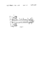
- FIG. 3 is a sectional side elevational view of an embodiment of the invention.
- FIG. 3 shows a practical embodiment of the invention.
- a die stem 3 is carried by a die stem slide 1 through a die stem retainer 2 or the like, as in a conventional die stem.
- the die stem 3 has an inner bore 3a receiving an inner sleeve 7.
- the inner sleeve 7 is fixed at its rear end to the die stem 3 by means of a nut 8 or the like means.
- the length of the inner sleeve 7 is so selected as not to project from the end of the die stem 3.
- a thread 7a is formed on the inner peripheral surface of the inner sleeve 7, so as to constitute a first connecting construction.
- a die holder 6 incorporating a die 4 and a die backer 5 is provided at its rear end portion with a rear end projection 6a adapted to be received by the end portion of the bore of the sleeve 7.
- the rear end projection 6a is provided with a thread 6b formed on the outer periphery thereof and adapted for making a screwing engagement with the aforementioned thread 7a.
- the connecting construction constituted by the thread or the bayonet is provided at the inner side of the juncture surfaces of the die stem 3 and the die holder 6, so that the full extrusion power exerted in the direction of the arrow F on the die holder 6 and the die stem 3 is not applied to the connecting portion 7a, 6b constituted by the threads.
- the present invention provides an improved sleeve type die stem suitable for use in indirect extrusion press.
Abstract
A die stem for an extrusion press connected at its one end to a die holder including a first connecting construction such as a screw or a bayonet provided in the inner bore of the end portion of a sleeve received by the inner bore of the die stem, and a second connecting construction such as a screw or a bayonet provided at the rear end projection of the die holder, the second connecting construction being adapted to cooperate with the first connecting construction, whereby the compression stress at the connecting portion thereof due to the extrusion force is prevented from taking place.
Description
Field of the Invention
This invention relates to a die stem for use in an extrusion press, and particularly to a sleeve type die stem.
Description of the Prior Art
In the die stem of a type adapted to be connected at its end to a die holder incorporating a die or a die backer, such as a die stem for use in an indirect extrusion press, a compression force is generated in the connecting construction during the extrusion so as to shorten the life of the die stem, thus hindering the safe operation of the whole apparatus.
As is well known, in the indirect extrusion press, it is a common practice to use a die stem unitarily connected at its end to a die holder, through a connecting construction such as a screw or a bayonet, to a die holder incorporating a die, die backer and so forth. In such a die stem, however, the stress concentration factor is impractically large. In fact, this factor is as large as on the order of 2 to 3 or larger. During the extrusion, the full extrusion power is concentrated on the die stem and the die holder, so that the resulting compression stress attains a considerably high level. Consequently, the life of the conventional die stem is rendered impractically short, so as to jeopardize the safe operation of the whole apparatus.
FIGS. 1 and 2 show typical examples of conventional die stems. More specifically, FIG. 1. shows a die stem of a type having no sleeve. In this die stem, as will be seen from the illustration thereof, the die stem 3 is held by a die stem slide 1 through a die stem retainer 2 or the like. In such illustrated example, a thread 3b is formed at the end portion of the internal bore 3a of the die stem 3. On the other hand, a thread 6b adapted to engage the thread 3b is formed on the outer periphery of a rear end projection 6a of a die holder 6 incorporating a die 4 and a die backer 5. In use, the die stem 3 and the die holder 6 are made unitary, through the screwing engagement of both threads 3a, 6b. In this state, the front end of the die stem 3 and the rear end of the die holder 6 are held in contact with each other, as shown in FIG. 1.
FIG. 2 shows another example of a conventional die stem, in which a sleeve is incorporated. In this type of the die stem, an inner sleever 7 is received by an inner bore 3a of the die stem 3 which is held by the die stem slide 1 through the medium of a die stem retainer 2 or the like. The sleeve 7 is fixed at its rear end to the rear end of the die stem 3 by means of a nut 8 or like means. The inner sleeve 7 is provided at its end with an outer peripheral thread 7a, while the rear end projection 6a of a die holder 6 incorporating a die 4 and a die backer 5 is provided with an inner peripheral thread 6b adapted for engagement with the thread 7a of the inner sleeve. In use, the die stem 3 and the die holder 6 are fixed unitarily to each other, through the medium of the inner sleeve 7, by screwing engagement. In this type of the die stem, the die stem 3 is made to contact at its front end surface the rear end surface of the rear end projection 6a of the die holder 6.
As the extrusion power is exerted as shown by the arrow F in the extrusion stroke of the extrusion press, a large nominal compression stress is generated at the thread 3b of the die stem 3 in case of the arrangement as shown in FIG. 1, and at the thread 6b of the die holder 6 in case of the arrangement as shown in FIG. 2. Further, due to the stress concentration at the bottom of the thread, a stress 2 to 3 times as large as the nominal compression stress is generated at the thread and the bottom of the teeth. This large stress often causes a local plastic deformation at the bottom of the screw, resulting in a shortened life of the die stem. Alternatively, in order to avoid such an inconvenience through reducing the level of the nominal compression stress, it is necessary to reduce the inner diameter of the die holder 6. Although the connecting constructions in these examples are screws, the same disadvantages are caused in the die stem having a connecting construction constituted by bayonets.
The present invention has been made to overcome the above mentioned shortcomings of the prior art, and the object of the invention is to provide a die stem of long life so as to save cost due to the repeated replacement and repair of parts.
Another object of the invention is to provide a die stem to secure a safe operation of an extrusion press apparatus.
The above and the other objects of the invention are achieved by the following aspects of the invention. The first embodiment of the invention is directed to a die stem for extrusion press connected at its one end to a die holder, which comprises a first connecting means provided in the inner bore of the end portion of a sleeve received by the inner bore of the die stem, and a second connecting means provided at the rear end projection of the die holder, the second connecting means being adapted to cooperate with the first connecting means.
In the die stem of the invention as shown in the drawings, the first and second connecting means comprises a screw, although the first and second connecting means may comprise a bayonet (not shown).
Various other objects, features and attendant advantages of the present invention will be more fully appreciated as the same becomes better understood from the following detailed description when considered in connection with the accompanying drawings in which like reference characters designate like or corresponding parts throughout the several views, and wherein:
FIG. 1 is a sectional side elevational view of a typical example of conventional die stem.
FIG. 2 is a sectional side elevational view of another example of a conventional die stem.
FIG. 3 is a sectional side elevational view of an embodiment of the invention.
Hereinafter, the invention will be described through an embodiment with reference to the FIGURES. FIG. 3 shows a practical embodiment of the invention. A die stem 3 is carried by a die stem slide 1 through a die stem retainer 2 or the like, as in a conventional die stem. The die stem 3 has an inner bore 3a receiving an inner sleeve 7. The inner sleeve 7 is fixed at its rear end to the die stem 3 by means of a nut 8 or the like means. The length of the inner sleeve 7 is so selected as not to project from the end of the die stem 3. In the illustrated embodiment, a thread 7a is formed on the inner peripheral surface of the inner sleeve 7, so as to constitute a first connecting construction. An equivalent effect can be obtained when the thread 7 is substituted by bayonet to constitute a second type of connecting construction. On the other hand, a die holder 6 incorporating a die 4 and a die backer 5 is provided at its rear end portion with a rear end projection 6a adapted to be received by the end portion of the bore of the sleeve 7. The rear end projection 6a is provided with a thread 6b formed on the outer periphery thereof and adapted for making a screwing engagement with the aforementioned thread 7a. Thus, the die stem 5 and the die holder 6 are adapted to be connected unitarily to each other by the screwing engagement of the threads 7a and 6b.
It will be seen that, in the described embodiments, the connecting construction constituted by the thread or the bayonet is provided at the inner side of the juncture surfaces of the die stem 3 and the die holder 6, so that the full extrusion power exerted in the direction of the arrow F on the die holder 6 and the die stem 3 is not applied to the connecting portion 7a, 6b constituted by the threads.
Consequently, it does not become necessary to take into consideration the stress concentration which has had to be taken into account in the conventional arrangements described hereinabove. It is therefore possible to select and adopt an allowable stress large enough to approach the yielding point of the material. This in turn allows adoption of a large inner diameter of the die stem. Needless to say, the life thereof is thus prolonged to reduce the cost and to enhance safety.
Thus, the present invention provides an improved sleeve type die stem suitable for use in indirect extrusion press.
Obviously, new modifications and variations in the present invention are possible in light of the above teachings. It is therefore to be understood that within the scope of the appended claims the invention may be practiced otherwise than as specifically described herein.
Claims (4)
1. A die stem assembly for an extrusion press, comprising:
a elongate die stem having an axial bore therethrough and having a flat end surface at one end thereof, the bore being radially enlarged at said one end;
an elongate sleeve fitted in the die stem bore, and having one end radially enlarged complementally to the die stem bore;
a die holder having a flat, annular shoulder in abutting engagement with the die stem end surface and having an axial projection extending into said one end of the sleeve;
first connecting means engaged between the outer surface of the die holder projection and the inner surface of said one end of the sleeve; and
second connecting means engaged between the other end of the sleeve and die stem, holding the die holder and die stem together via the sleeve and connecting means, whereby axial compressive forces on said one end of the die holder and die stem are carried by the axially abutting shoulder and end surface and the connecting means remain substantially free of deforming stresses.
2. The die stem assembly of claim 1, wherein the first and second connecting means comprise a threaded portion.
3. A die stem assembly as claimed in claim 2, wherein:
said one end of said sleeve has threads on the inner surface thereof;
the outer surface of the die holder projection has threads thereon for cooperation with the sleeve threads, and with the sleeve threads comprises the first connecting means; and
the other end of the sleeve projects beyond the other end of the die stem and has a nut threaded thereon, comprising the second connecting means, whereby the sleeve and first and second connecting means serve merely to hold the die holder to the die stem, and axial compressive forces produced during extrusion are carried by the abutting shoulder and end surface.
4. The die stem assembly of claim 1 which further comprises:
a die mounted in said die holder; and
a die backer disposed within said die holder adjacent said die.
Applications Claiming Priority (2)
| Application Number | Priority Date | Filing Date | Title |
|---|---|---|---|
| JP1977141616U JPS5443073Y2 (en) | 1977-10-19 | 1977-10-19 | |
| JP52/141616[U] | 1977-10-19 |
Publications (1)
| Publication Number | Publication Date |
|---|---|
| US4251202A true US4251202A (en) | 1981-02-17 |
Family
ID=15296169
Family Applications (1)
| Application Number | Title | Priority Date | Filing Date |
|---|---|---|---|
| US05/946,327 Expired - Lifetime US4251202A (en) | 1977-10-19 | 1978-09-27 | Molding die stem with sleeve |
Country Status (3)
| Country | Link |
|---|---|
| US (1) | US4251202A (en) |
| JP (1) | JPS5443073Y2 (en) |
| DE (1) | DE2844196A1 (en) |
Cited By (5)
| Publication number | Priority date | Publication date | Assignee | Title |
|---|---|---|---|---|
| US4519713A (en) * | 1983-03-21 | 1985-05-28 | The Quaker Oats Company | Apparatus and method for relining extruder barrels |
| US4895506A (en) * | 1987-12-02 | 1990-01-23 | Danieli & C. Officine Meccaniche Spa | Extrusion press |
| US5680894A (en) * | 1996-10-23 | 1997-10-28 | Lindberg Corporation | Apparatus for the injection molding of a metal alloy: sub-ring concept |
| CN102962279A (en) * | 2012-12-11 | 2013-03-13 | 阎善武 | Reverse extruder |
| CN103252375A (en) * | 2013-05-30 | 2013-08-21 | 太原重工股份有限公司 | Fixing device for extrusion rod of extruding machine |
Families Citing this family (1)
| Publication number | Priority date | Publication date | Assignee | Title |
|---|---|---|---|---|
| CN103447333B (en) * | 2013-08-19 | 2015-10-28 | 无锡源创机械科技有限公司 | A kind of reverse extrusion bar bias adjusts central authority |
Citations (11)
| Publication number | Priority date | Publication date | Assignee | Title |
|---|---|---|---|---|
| US1702619A (en) * | 1927-06-27 | 1929-02-19 | Jr Sumner B Sargent | Liner pump |
| US2462308A (en) * | 1945-10-25 | 1949-02-22 | Watson Stillman Co | Injection molding machine |
| US2529146A (en) * | 1948-03-15 | 1950-11-07 | Waldes Kohinoor Inc | Injection molding apparatus |
| US2533885A (en) * | 1944-03-07 | 1950-12-12 | Elastic Stop Nut Corp | Coupling |
| US2747226A (en) * | 1952-07-25 | 1956-05-29 | Richardson Co | Antistringing injection nozzle |
| US2754545A (en) * | 1952-01-04 | 1956-07-17 | Tube Turns Plastics Inc | Injection machine |
| US2973551A (en) * | 1958-12-17 | 1961-03-07 | American Can Co | Nozzle |
| US3232638A (en) * | 1962-11-26 | 1966-02-01 | American Mach & Foundry | Prestressed tubes and rods |
| US3698640A (en) * | 1971-07-14 | 1972-10-17 | Tempcraft Tool & Mold | Wax injection nozzle |
| US3913949A (en) * | 1974-11-08 | 1975-10-21 | United Technologies Corp | Shrouded flammable fluid carrying tube |
| US3934626A (en) * | 1974-05-17 | 1976-01-27 | Hall John L | Anti-drip injection nozzle for plastic molding |
Family Cites Families (2)
| Publication number | Priority date | Publication date | Assignee | Title |
|---|---|---|---|---|
| DE1127305B (en) * | 1959-05-13 | 1962-04-12 | Hydraulik Gmbh | Press disc for indirect metal extrusion |
| JPS5138317B2 (en) * | 1971-11-25 | 1976-10-21 |
-
1977
- 1977-10-19 JP JP1977141616U patent/JPS5443073Y2/ja not_active Expired
-
1978
- 1978-09-27 US US05/946,327 patent/US4251202A/en not_active Expired - Lifetime
- 1978-10-11 DE DE2844196A patent/DE2844196A1/en not_active Withdrawn
Patent Citations (11)
| Publication number | Priority date | Publication date | Assignee | Title |
|---|---|---|---|---|
| US1702619A (en) * | 1927-06-27 | 1929-02-19 | Jr Sumner B Sargent | Liner pump |
| US2533885A (en) * | 1944-03-07 | 1950-12-12 | Elastic Stop Nut Corp | Coupling |
| US2462308A (en) * | 1945-10-25 | 1949-02-22 | Watson Stillman Co | Injection molding machine |
| US2529146A (en) * | 1948-03-15 | 1950-11-07 | Waldes Kohinoor Inc | Injection molding apparatus |
| US2754545A (en) * | 1952-01-04 | 1956-07-17 | Tube Turns Plastics Inc | Injection machine |
| US2747226A (en) * | 1952-07-25 | 1956-05-29 | Richardson Co | Antistringing injection nozzle |
| US2973551A (en) * | 1958-12-17 | 1961-03-07 | American Can Co | Nozzle |
| US3232638A (en) * | 1962-11-26 | 1966-02-01 | American Mach & Foundry | Prestressed tubes and rods |
| US3698640A (en) * | 1971-07-14 | 1972-10-17 | Tempcraft Tool & Mold | Wax injection nozzle |
| US3934626A (en) * | 1974-05-17 | 1976-01-27 | Hall John L | Anti-drip injection nozzle for plastic molding |
| US3913949A (en) * | 1974-11-08 | 1975-10-21 | United Technologies Corp | Shrouded flammable fluid carrying tube |
Cited By (6)
| Publication number | Priority date | Publication date | Assignee | Title |
|---|---|---|---|---|
| US4519713A (en) * | 1983-03-21 | 1985-05-28 | The Quaker Oats Company | Apparatus and method for relining extruder barrels |
| US4895506A (en) * | 1987-12-02 | 1990-01-23 | Danieli & C. Officine Meccaniche Spa | Extrusion press |
| US5680894A (en) * | 1996-10-23 | 1997-10-28 | Lindberg Corporation | Apparatus for the injection molding of a metal alloy: sub-ring concept |
| CN102962279A (en) * | 2012-12-11 | 2013-03-13 | 阎善武 | Reverse extruder |
| CN102962279B (en) * | 2012-12-11 | 2015-05-20 | 阎善武 | Reverse extruder |
| CN103252375A (en) * | 2013-05-30 | 2013-08-21 | 太原重工股份有限公司 | Fixing device for extrusion rod of extruding machine |
Also Published As
| Publication number | Publication date |
|---|---|
| JPS5443073Y2 (en) | 1979-12-13 |
| JPS5465936U (en) | 1979-05-10 |
| DE2844196A1 (en) | 1979-04-26 |
Similar Documents
| Publication | Publication Date | Title |
|---|---|---|
| US2452278A (en) | Tube coupling device | |
| US4097163A (en) | Method of swage joining a rod end to a tube and the product thereof | |
| CA2183450A1 (en) | Blind fastener with deformable sleeve | |
| US2084439A (en) | Piston and piston rod assembly | |
| US4251202A (en) | Molding die stem with sleeve | |
| US4835428A (en) | Setting device for vehicle generator | |
| US5213006A (en) | Bicycle stem mechanism having internal rigidifying washer | |
| GB2240603A (en) | Blind rivet nut | |
| US5492211A (en) | Bicycle freewheel gear cluster mounting structure | |
| US5078562A (en) | Self-locking threaded fastening arrangement | |
| CA2076908A1 (en) | Axially-adjustable attachment of a rod to a member | |
| US5473962A (en) | Bicycle hanger structure | |
| CN1036022C (en) | An axially-adjustable attachment of a rod to a member | |
| US3288501A (en) | Ball joint | |
| US4097075A (en) | Tire valve core | |
| US2962073A (en) | Resilient mounting for a valve stem assembly or the like | |
| JPS5925522Y2 (en) | rolling roll | |
| KR830000223Y1 (en) | Sleeve type in indirect extrusion press | |
| JP4931200B2 (en) | Ejector pin | |
| GB2102531A (en) | A combination of a support body and an annular pulley body | |
| CN216180097U (en) | Screw up stock | |
| US3831418A (en) | Extrusion die assembly | |
| US2788044A (en) | Self-locking nut and threaded male member assembly, and parts thereof | |
| JPH0111509Y2 (en) | ||
| CN219827428U (en) | Locking fastening component with one-way bearing structure |