US4245144A - Spark-machining apparatus - Google Patents
Spark-machining apparatus Download PDFInfo
- Publication number
- US4245144A US4245144A US05/912,415 US91241578A US4245144A US 4245144 A US4245144 A US 4245144A US 91241578 A US91241578 A US 91241578A US 4245144 A US4245144 A US 4245144A
- Authority
- US
- United States
- Prior art keywords
- electrode
- mounting plate
- plate
- face
- walls
- Prior art date
- Legal status (The legal status is an assumption and is not a legal conclusion. Google has not performed a legal analysis and makes no representation as to the accuracy of the status listed.)
- Expired - Lifetime
Links
- 238000009760 electrical discharge machining Methods 0.000 title claims abstract description 12
- OKTJSMMVPCPJKN-UHFFFAOYSA-N Carbon Chemical group [C] OKTJSMMVPCPJKN-UHFFFAOYSA-N 0.000 claims abstract description 13
- 229910002804 graphite Inorganic materials 0.000 claims abstract description 13
- 239000010439 graphite Substances 0.000 claims abstract description 13
- 239000012530 fluid Substances 0.000 claims abstract 3
- 230000003014 reinforcing effect Effects 0.000 abstract description 3
- 238000005553 drilling Methods 0.000 abstract 1
- 239000007788 liquid Substances 0.000 description 4
- CWYNVVGOOAEACU-UHFFFAOYSA-N Fe2+ Chemical compound [Fe+2] CWYNVVGOOAEACU-UHFFFAOYSA-N 0.000 description 2
- 230000003628 erosive effect Effects 0.000 description 2
- 238000003754 machining Methods 0.000 description 2
- 239000002245 particle Substances 0.000 description 2
- 239000000853 adhesive Substances 0.000 description 1
- 230000001070 adhesive effect Effects 0.000 description 1
- 239000002184 metal Substances 0.000 description 1
- 230000002093 peripheral effect Effects 0.000 description 1
Images
Classifications
-
- B—PERFORMING OPERATIONS; TRANSPORTING
- B23—MACHINE TOOLS; METAL-WORKING NOT OTHERWISE PROVIDED FOR
- B23H—WORKING OF METAL BY THE ACTION OF A HIGH CONCENTRATION OF ELECTRIC CURRENT ON A WORKPIECE USING AN ELECTRODE WHICH TAKES THE PLACE OF A TOOL; SUCH WORKING COMBINED WITH OTHER FORMS OF WORKING OF METAL
- B23H1/00—Electrical discharge machining, i.e. removing metal with a series of rapidly recurring electrical discharges between an electrode and a workpiece in the presence of a fluid dielectric
- B23H1/04—Electrodes specially adapted therefor or their manufacture
Definitions
- This invention relates to improvements in or relating to spark-machining apparatus.
- the present invention provides an electrode mounting plate for mounting a graphite electrode in spark-machining apparatus, the plate having one face arranged to mount a graphite electrode, and an opposite face arranged to define a chamber which can be connected to a dielectric circulation system of said spark-machining apparatus.
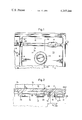
- FIG. 1 shows an electrode mounting plate embodying the invention and seen from the rear--that is the side remote from the electrode, and
- FIG. 2 is a section along the line 2--2 of FIG. 1, viewed in the direction of the arrow.
- an electrode mounting plate 11 is shown for use in mounting a graphite electrode of a spark-machining apparatus.
- a graphite electrode is indicated by the broken outline in FIG. 1 and is partially illustrated in FIG. 2, reference 10 indicating the graphite electrode.
- the operating gap between the electrode and a work-piece (which will usually be of ferrous metal) is flooded in use with a liquid dielectric in order to rinse away the ferrous particles eroded by the arcing.
- the electrode 10 is provided with rinsing bores 24 which are connected to a dielectric circulation system.
- the electrode mounting plate 11 is itself carried by a electrode assembly mounting plate 23 located on the electrode feed shaft of the spark machining apparatus indicated in general by numeral 30.
- the side of the electrode mounting plate 11 remote from the electrode defines a trough 13 which is covered over in use by the electrode assembly mounting plate 28 to define a chamber for the liquid dielectric.
- the electrode mounting plate On the side remote from the graphite block 10 (FIG. 2) the electrode mounting plate has a peripheral flange or wall 12, so that the plate seen from this side is in the shape of a flat trough defining a shallow chamber 13. Reinforcing ribs 14 are provided cross-wise on the inside of the trough, which trough defines the dielectric chamber. Bosses 16 are provided in the ribs 14, the tops of the bosses being flush with the distal edge of the flange 12. Tapped blind holes 18 are provided in the bosses 16 to enable the electrode mounting plate 11 to be itself mounted in the spark-machining apparatus 30. In addition, bosses 20, likewise having tops flush with the flange, are provided at the points of intersection of ribs 14. A circular, crater-like boss 22, not projecting so far as to be flush with the flange is provided to receive a centering ring (not shown), by means of which the electrode mounting plate 11 is positioned on its own mounting 28.
- the rinsing bores 24 in the electrode 10 can be bored with ease in a perpendicular direction and through the face of the electrode mounting the plate 13 so that uniform rinsing and therefore better eroding efficiency on the workpiece can be achieved.
- Electrode plate 11 for chucking graphite electrodes for the electroerosive machining of workpieces, in which the operating gap between electrode and workpiece is flooded by a liquid dielectric, wherein there is incorporated into the rear of the plate remote from the electrode a chamber which can be connected to the dielectric circulation and which extends substantially over the entire extent of the plate.
- the plate viewed from the rear, is in the form of a trough with reinforcing ribs spanning the interior of the trough.
Landscapes
- Engineering & Computer Science (AREA)
- Manufacturing & Machinery (AREA)
- Mechanical Engineering (AREA)
- Electrical Discharge Machining, Electrochemical Machining, And Combined Machining (AREA)
Abstract
An electrode mounting plate having a flat face adhesively bonded to a graphite electrode and an opposite face forming a trough with reinforcing ribs, the trough being covered in use by the mounting plate of the spark machining apparatus to define a chamber communicating with the dielectric circulation system of the apparatus. Flow passages for the dielectric fluid are formed by drilling holes through the mounted electrode and the flat face of the electrode mounting plate.
Description
This invention relates to improvements in or relating to spark-machining apparatus.
In a spark-machining apparatus used in Germany it is known to flood the operating gap between a graphite electrode and a work-piece with liquid dielectric in order to flush away particles eroded by the arc. For this purpose, rinsing bores are bored through the graphite electrode to meet rinsing channels connected in a dielectric circulation system. This operation is difficult for complicated electrode shapes and, depending on the size and length of the channels, may fail to provide uniform rinsing. The result of non-uniform rinsing is that, in inadequately rinsed areas, breaks in contact occur during erosion and necessitate subsequent hand-machining.
It is an object of the invention to provide a means for improving the dielectric rinsing of spark-machining apparatus.
The present invention provides an electrode mounting plate for mounting a graphite electrode in spark-machining apparatus, the plate having one face arranged to mount a graphite electrode, and an opposite face arranged to define a chamber which can be connected to a dielectric circulation system of said spark-machining apparatus.
By way of example only an illustrative embodiment of the invention will now be described with reference to the accompanying drawing, in which:
FIG. 1 shows an electrode mounting plate embodying the invention and seen from the rear--that is the side remote from the electrode, and
FIG. 2 is a section along the line 2--2 of FIG. 1, viewed in the direction of the arrow.
Referring to the drawing, an electrode mounting plate 11 is shown for use in mounting a graphite electrode of a spark-machining apparatus. Such a graphite electrode is indicated by the broken outline in FIG. 1 and is partially illustrated in FIG. 2, reference 10 indicating the graphite electrode.
The operating gap between the electrode and a work-piece (which will usually be of ferrous metal) is flooded in use with a liquid dielectric in order to rinse away the ferrous particles eroded by the arcing. To achieve this the electrode 10 is provided with rinsing bores 24 which are connected to a dielectric circulation system. The electrode mounting plate 11 is itself carried by a electrode assembly mounting plate 23 located on the electrode feed shaft of the spark machining apparatus indicated in general by numeral 30. The side of the electrode mounting plate 11 remote from the electrode defines a trough 13 which is covered over in use by the electrode assembly mounting plate 28 to define a chamber for the liquid dielectric.
On the side remote from the graphite block 10 (FIG. 2) the electrode mounting plate has a peripheral flange or wall 12, so that the plate seen from this side is in the shape of a flat trough defining a shallow chamber 13. Reinforcing ribs 14 are provided cross-wise on the inside of the trough, which trough defines the dielectric chamber. Bosses 16 are provided in the ribs 14, the tops of the bosses being flush with the distal edge of the flange 12. Tapped blind holes 18 are provided in the bosses 16 to enable the electrode mounting plate 11 to be itself mounted in the spark-machining apparatus 30. In addition, bosses 20, likewise having tops flush with the flange, are provided at the points of intersection of ribs 14. A circular, crater-like boss 22, not projecting so far as to be flush with the flange is provided to receive a centering ring (not shown), by means of which the electrode mounting plate 11 is positioned on its own mounting 28.
It can be seen that practically the entire rear surface of the electrode mounting plate--with the exception of the bosses--can be flooded with dielectric, so that it is possible at any position to sink bores 24 through the electrode 10 and through the plate surface. The electrode itself, as shown by 26, is cemented onto the plate 11 for which graphite adhesives, which are obtainable commercially, are used.
Thus, the rinsing bores 24 in the electrode 10 can be bored with ease in a perpendicular direction and through the face of the electrode mounting the plate 13 so that uniform rinsing and therefore better eroding efficiency on the workpiece can be achieved.
A brief summary of what has been described will now be given.
The plate, viewed from the rear, is in the form of a trough with reinforcing ribs spanning the interior of the trough.
Claims (1)
1. A mounting plate for carrying a graphite electrode on the electrode assembly mounting plate in a spark machining apparatus, comprising
a broad and generally flat plate with rinsing bores therethrough and having opposite faces and a periphery, one face being flat for securing the graphite electrode thereto, the other face having walls, ribs and bosses protruding therefrom,
the walls extending around the periphery of the plate to engage the electrode assembly mounting plate and embrace a chamber for dielectric fluid adjacent the other face,
the ribs traversing the chamber in multiple directions and extending to the walls, and the ribs having a height from said other face less than the height of the walls and thereby permitting free flow of the dielectric fluid within the chamber, and
the bosses having a height from said other face identical to the height of the walls to lie flush therewith and to engage the electrode assembly mounting plate of the spark machining apparatus, certain of the bosses having tapped apertures therein and normal to the plate.
Applications Claiming Priority (2)
| Application Number | Priority Date | Filing Date | Title |
|---|---|---|---|
| DE2743275 | 1977-09-27 | ||
| DE2743275A DE2743275C2 (en) | 1977-09-27 | 1977-09-27 | Clamping device for a graphite electrode for the electrical discharge machining of workpieces |
Publications (1)
| Publication Number | Publication Date |
|---|---|
| US4245144A true US4245144A (en) | 1981-01-13 |
Family
ID=6019924
Family Applications (1)
| Application Number | Title | Priority Date | Filing Date |
|---|---|---|---|
| US05/912,415 Expired - Lifetime US4245144A (en) | 1977-09-27 | 1978-06-05 | Spark-machining apparatus |
Country Status (9)
| Country | Link |
|---|---|
| US (1) | US4245144A (en) |
| JP (1) | JPS5454394A (en) |
| BR (1) | BR7805485A (en) |
| CH (1) | CH628274A5 (en) |
| DE (1) | DE2743275C2 (en) |
| FR (1) | FR2403863A1 (en) |
| GB (1) | GB1604107A (en) |
| IT (1) | IT1107283B (en) |
| SE (1) | SE7806339L (en) |
Cited By (4)
| Publication number | Priority date | Publication date | Assignee | Title |
|---|---|---|---|---|
| US4647748A (en) * | 1984-05-17 | 1987-03-03 | Smith International, Inc. | Graphite electrode construction and method of making |
| US4924051A (en) * | 1988-11-18 | 1990-05-08 | Sebzda Sr Jack | Split grip tip for mounting of electrode blanks |
| USRE33249E (en) * | 1982-10-18 | 1990-07-03 | Erowa A.G. | Coupling device |
| US20080240878A1 (en) * | 2007-03-28 | 2008-10-02 | Invention To Controlled Automation, Incorporated | Drilling apparatus and method |
Families Citing this family (4)
| Publication number | Priority date | Publication date | Assignee | Title |
|---|---|---|---|---|
| DE102008018638B3 (en) * | 2008-04-11 | 2009-10-01 | Gottfried Schleinkofer | Electrical conductive and mechanical fixed connection arrangement for fixing eroded electrode at holder for eroded machine, has tapped hole designed such that recess is provided on lower side of metal carrier plate for receiving adhesive |
| DE102014005087B4 (en) | 2013-04-09 | 2015-03-05 | Gtd Graphit Technologie Gmbh | Process for producing an erosion graphite electrode from a blank made of erosion graphite, elastic adapter with the erosion graphite electrode according to the method and erosion graphite electrode obtained according to the method |
| DE202013003251U1 (en) | 2013-04-09 | 2013-04-25 | Gtd Graphit Technologie Gmbh | Erodiergraphitelektrode |
| CN110052676B (en) * | 2018-01-19 | 2021-02-12 | 苏州汉扬精密电子有限公司 | Electrode structure |
Citations (3)
| Publication number | Priority date | Publication date | Assignee | Title |
|---|---|---|---|---|
| SU187501A1 (en) * | В. П. Киселев , Ф. Ф. Садыкова | CARBON POTTER / NISS ELECTRODE TOOL | ||
| US2909641A (en) * | 1958-05-02 | 1959-10-20 | Republic Aviat Corp | Tool for electro-shaping |
| US3783224A (en) * | 1969-05-08 | 1974-01-01 | Automotive Pattern Co | Edm electrode construction and method of making same |
Family Cites Families (3)
| Publication number | Priority date | Publication date | Assignee | Title |
|---|---|---|---|---|
| US3390247A (en) * | 1966-06-27 | 1968-06-25 | Elox Inc | Coolant circulation system for electrical discharge machining apparatus |
| JPS5240228Y2 (en) * | 1973-05-07 | 1977-09-10 | ||
| JPS5131196B2 (en) * | 1973-10-25 | 1976-09-04 |
-
1977
- 1977-09-27 DE DE2743275A patent/DE2743275C2/en not_active Expired
-
1978
- 1978-05-25 GB GB22837/78A patent/GB1604107A/en not_active Expired
- 1978-05-26 CH CH576778A patent/CH628274A5/en not_active IP Right Cessation
- 1978-05-31 SE SE7806339A patent/SE7806339L/en unknown
- 1978-06-05 US US05/912,415 patent/US4245144A/en not_active Expired - Lifetime
- 1978-06-09 JP JP6900378A patent/JPS5454394A/en active Pending
- 1978-06-30 IT IT68537/78A patent/IT1107283B/en active
- 1978-07-21 FR FR7821789A patent/FR2403863A1/en active Granted
- 1978-08-24 BR BR7805485A patent/BR7805485A/en unknown
Patent Citations (3)
| Publication number | Priority date | Publication date | Assignee | Title |
|---|---|---|---|---|
| SU187501A1 (en) * | В. П. Киселев , Ф. Ф. Садыкова | CARBON POTTER / NISS ELECTRODE TOOL | ||
| US2909641A (en) * | 1958-05-02 | 1959-10-20 | Republic Aviat Corp | Tool for electro-shaping |
| US3783224A (en) * | 1969-05-08 | 1974-01-01 | Automotive Pattern Co | Edm electrode construction and method of making same |
Cited By (5)
| Publication number | Priority date | Publication date | Assignee | Title |
|---|---|---|---|---|
| USRE33249E (en) * | 1982-10-18 | 1990-07-03 | Erowa A.G. | Coupling device |
| US4647748A (en) * | 1984-05-17 | 1987-03-03 | Smith International, Inc. | Graphite electrode construction and method of making |
| US4924051A (en) * | 1988-11-18 | 1990-05-08 | Sebzda Sr Jack | Split grip tip for mounting of electrode blanks |
| US20080240878A1 (en) * | 2007-03-28 | 2008-10-02 | Invention To Controlled Automation, Incorporated | Drilling apparatus and method |
| US8021086B2 (en) | 2007-03-28 | 2011-09-20 | Controlled Automation, Incorporated | Drilling apparatus and method |
Also Published As
| Publication number | Publication date |
|---|---|
| SE7806339L (en) | 1979-03-28 |
| DE2743275A1 (en) | 1979-04-05 |
| IT1107283B (en) | 1985-11-25 |
| CH628274A5 (en) | 1982-02-26 |
| JPS5454394A (en) | 1979-04-28 |
| GB1604107A (en) | 1981-12-02 |
| FR2403863B1 (en) | 1983-10-07 |
| DE2743275C2 (en) | 1983-12-01 |
| IT7868537A0 (en) | 1978-06-30 |
| FR2403863A1 (en) | 1979-04-20 |
| BR7805485A (en) | 1979-04-17 |
Similar Documents
| Publication | Publication Date | Title |
|---|---|---|
| US4245144A (en) | Spark-machining apparatus | |
| US4263493A (en) | Spark erosion cutting apparatus with controlled flushing medium flow | |
| US2813966A (en) | Rough and finish machining with stepped electrode | |
| US3293166A (en) | Electrode for electrolytic machining | |
| US3445372A (en) | Apparatus for electrochemically removing the surface layer from a workpiece | |
| US3575631A (en) | Electrode for electrohydraulic high-energy-rate metal forming | |
| US5266776A (en) | Plasma arc cutting and welding tip | |
| US3467593A (en) | Electrochemical deburring under pressure | |
| US3386907A (en) | Electro-erosive machining apparatus | |
| US3919515A (en) | Electrode holder for EDM | |
| KR100447693B1 (en) | Apparatus for electrochemically processing recesses | |
| US3658684A (en) | Electrochemical machining apparatus | |
| US3875038A (en) | Electrolytic machining apparatus | |
| US3796852A (en) | Electrical discharge machining tool | |
| CN211332136U (en) | Electric arc micro-explosion and cutting combined machining device | |
| US3479273A (en) | Apparatus for electro-chemical machining with a rotating grooved electrode tool | |
| US5254827A (en) | Chip removing device of electro-discharge machine | |
| CA1135798A (en) | Stud welding device with cylindrical positioning guide member | |
| JP3379362B2 (en) | Plasma cutting torch | |
| SU1539005A1 (en) | Electrode-tool for electrochemical machining | |
| CN222403829U (en) | Electrical discharge machining device | |
| US3445617A (en) | Electro-erosive method and apparatus for making a die member complemental to a die member of the rule type | |
| SU904959A1 (en) | Tool-electrode | |
| US3654122A (en) | Workpiece holding fixture for electrolytic shaping apparatus | |
| US3383302A (en) | Electrical stock removal electrode |