US4244237A - Tilt steering column mechanism - Google Patents
Tilt steering column mechanism Download PDFInfo
- Publication number
- US4244237A US4244237A US06/042,746 US4274679A US4244237A US 4244237 A US4244237 A US 4244237A US 4274679 A US4274679 A US 4274679A US 4244237 A US4244237 A US 4244237A
- Authority
- US
- United States
- Prior art keywords
- frusto
- conical
- steering column
- conical detent
- spring
- Prior art date
- Legal status (The legal status is an assumption and is not a legal conclusion. Google has not performed a legal analysis and makes no representation as to the accuracy of the status listed.)
- Expired - Lifetime
Links
Images


Classifications
-
- B—PERFORMING OPERATIONS; TRANSPORTING
- B62—LAND VEHICLES FOR TRAVELLING OTHERWISE THAN ON RAILS
- B62D—MOTOR VEHICLES; TRAILERS
- B62D1/00—Steering controls, i.e. means for initiating a change of direction of the vehicle
- B62D1/02—Steering controls, i.e. means for initiating a change of direction of the vehicle vehicle-mounted
- B62D1/16—Steering columns
- B62D1/18—Steering columns yieldable or adjustable, e.g. tiltable
- B62D1/184—Mechanisms for locking columns at selected positions
-
- Y—GENERAL TAGGING OF NEW TECHNOLOGICAL DEVELOPMENTS; GENERAL TAGGING OF CROSS-SECTIONAL TECHNOLOGIES SPANNING OVER SEVERAL SECTIONS OF THE IPC; TECHNICAL SUBJECTS COVERED BY FORMER USPC CROSS-REFERENCE ART COLLECTIONS [XRACs] AND DIGESTS
- Y10—TECHNICAL SUBJECTS COVERED BY FORMER USPC
- Y10T—TECHNICAL SUBJECTS COVERED BY FORMER US CLASSIFICATION
- Y10T403/00—Joints and connections
- Y10T403/32—Articulated members
- Y10T403/32254—Lockable at fixed position
- Y10T403/32262—At selected angle
- Y10T403/32319—At selected angle including pivot stud
- Y10T403/32327—At selected angle including pivot stud including radially spaced detent or latch component
- Y10T403/32361—Engaging recess in radial face
-
- Y—GENERAL TAGGING OF NEW TECHNOLOGICAL DEVELOPMENTS; GENERAL TAGGING OF CROSS-SECTIONAL TECHNOLOGIES SPANNING OVER SEVERAL SECTIONS OF THE IPC; TECHNICAL SUBJECTS COVERED BY FORMER USPC CROSS-REFERENCE ART COLLECTIONS [XRACs] AND DIGESTS
- Y10—TECHNICAL SUBJECTS COVERED BY FORMER USPC
- Y10T—TECHNICAL SUBJECTS COVERED BY FORMER US CLASSIFICATION
- Y10T74/00—Machine element or mechanism
- Y10T74/20—Control lever and linkage systems
- Y10T74/20576—Elements
- Y10T74/20636—Detents
Definitions
- My invention relates to a tilt steering column mechanism, for use in a commercial vehicle, in particular in a truck of the cab-over-engine or forward cab variety, which permits the tilting of the steering column in a fore-and-aft direction.
- Tiltable steering columns have become quite popular, especially for commercial vehicles, such as trucks of the cab-over-engine or forward cab variety, wherein the driver's seat is situated nearly directly above the front axle and the steering wheel is disposed at a slight angle to a horizontal plane.
- the ability to tilt the steering column greatly enhances the comfort of the driver by permitting the operator to position the steering wheel in a comfortable driving position and by facilitating access to and egress from the driver's station.
- My invention is an improvement to the detent type of tilt steering column mechanisms, such as are shown in the following U.S. Pat. Nos.
- a detent mechanism is operable to engage a movable member having a plurality of holes, slots or teeth, each of which corresponds to a separate, discrete position of the steering column.
- a handle operated, rotary cam and pin follower actuated, frustoconical tilt steering column lock mechanism that mechanically locks and unlocks the tilt steering column in one planar pivotal movement as opposed to Michalic which requires two planes of pivotal movement; and one which provides a positive mechanical lock between the slideable bracket on the steering column and the stationary bracket on the vehicle cab frame, rather than the frictional clamping arrangements of Michalic and Schenten, or the spring force in combination with the release of the Bowden cable of Groves, and one which utilizes the conventional universal connection at the base of the tilt steering column for the tilt axis.
- the tilt steering column mechanism makes full use of a conventional fixed steering column assembly and the universal joint at the base thereof which allows the upper end supporting the steering wheel to swing fore-and-aft.
- my improved tilt steering column mechanism comprises a support bracket means connected to a vehicle cab frame for supporting the steering column above the universal joint connection.
- a slider bracket means is connected to the steering column which has arm means passing forwardly into the support bracket means for limiting tilting of the steering column to the fore-and-aft direction.
- Frusto-conical detent means are slideably mounted to the support bracket means and are movable transversely with respect to the steering column for locking the arm means of the slider bracket means to the support bracket means at selected frusto-conical detent receiving means which are provided on one lateral side of the arm means of the slider bracket means which correspond to one of several selectable fore-and-aft tilt positions of the steering column.
- First spring means are carried on the support bracket means and engage the frusto-conical detent means for moving the frusto-conical detent means out of engagement with the frusto-conical detent receiving means.
- a rotary cam means is resiliently mounted to the support bracket and has a cam follower pin fixed to the frusto-conical detent means.
- a second spring means which is of lesser magnitude than and opposses the first spring means, urges the rotary cam means into engagement with the cam follower pin means and the frusto-conical detent means into engagement with the frusto-conical receiving means.
- a lever means is fixed to the frusto-conical detent means for moving the frusto-conical means into engagement with the frusto-conical detent receiving means by rotating the cam follower pin means along a rising cam land surface of the rotary cam means and loading the opposing spring means and for moving the frusto-conical detent means out from engagement with the frusto-conical detent receiving means by rotating the cam follower pin means in a reverse direction along a now falling cam land surface of the rotary cam means and releasing the loading on the opposing spring means whereby the first spring means moves the frusto-conical detent means out from the frusto-conical detent receiving means against the lesser force of the second spring means.
- the support bracket means comprise a base plate fixed to the vehicle cab frame and has three spaced-apart flange members which project forwardly from the base.
- the flange members each have at least one flat lateral side perpendicular to the base plate.
- the slider bracket means comprise two identical spaced-apart arm means each having a pedestal fixed to a base on the steering column and each having two parallel lateral flat sides which project forwardly from the pedestal and pass along side of the flat lateral sides of the flange members.
- the arm means each have an elongated slot on the identical lateral flat side and a plurality of uniformly spaced-apart frusto-conical holes on the indentical opposite lateral flat side which taper downwardly into the slot.
- the frusto-conical detent means comprise an elongated locking bar which has two longitudinally spaced-apart frusto-conical portions thereon and is slideably carried in matching transverse bores provided in each of the flat lateral sides of the flange members.
- the frusto-conical portions each taper downwardly in the same axial direction into an elongated anchor portion of a size which passes through the slot in each arm means thereby anchoring the respective arm means to the flange members of the support bracket means.
- one frusto-conical portion is slideably mounted to one end of the locking bar and a third spring means cooperating with the first spring means is provided on the one end of the locking bar for resiliently connecting the frusto-conical portion thereto and for axially positioning both frusto-conical portions in respective aligned frusto-conical holes in the arm means.
- the rotary cam means includes a cup connected to the side opposite of the flat lateral side of one flange memer. A pair of diametrically opposite slots are provided on the cup and extend axially from the rim towards the bottom.
- the rotary cam means has a closed bottom cylindrical body portion which slip fits inside the cup and has radially projecting lugs which are slip fit in the slots.
- the cup and the rotary cam means each have a hole centered in the bottom thereof, through which the locking bar passes.
- the second spring means comprise a thrust washer and a plurality of spring washers sleeved over the locking bar between the bottom of the cup and the outside bottom of the rotary cam means.
- the cam follower pin means is fixed to an end portion of the locking bar which passes through the holes in the bottoms of the cup and rotary cam means, and the handle is fixed to the end of the locking bar adjacent the cam follower pin means.
- the first spring means comprise a compression spring which is sleeved over the locking bar and which has one end contacting one flange member on the side opposite of the flat lateral side and the other end contacting a flat washer which is sleeved over and connected to the bar.
- the third spring means comprise a pair of jam nuts screwed onto a threaded end portion of the locking bar against a flat washer which abuts a spring washer which in turn abuts the large end of the slideably mounted frusto-conical portion.
- the frusto-conical portions on the locking bar are unseated from the frusto-conical receiving holes in the slotted arm means of the slider bracket means by rotating the cam follower pin means, which is keyed to the locking bar, by means of the handle, which is also keyed to the locking bar, from the raised land cam surface to the lowered land cam surface, thereby releasing the loading on the opposing spring means whereupon the spring means of greater magnitude causes the locking bar to slide and unseat the frusto-conical detent portions from the frusto-conical detent receiving holes against the bias of the spring means of lesser magnitude.
- the anchor portions of the locking bar now extend across the entire width of the slotted arm means of the slider bracket means so that the slotted arm means of the slider bracket means are free to slide across the anchor portions on the locking bar and the steering column is free to pivot fore-and-aft, about the axis of the universal connection at the base of the steering column, to the selected new position of the steering wheel.
- the handle which is keyed to the locking bolt, is rotated back to its original position thereby rotating the cam follower pin means of the rotary cam means, which is also keyed to the locking shaft, from the lowered land cam surface to the raised land cam surface, drawing the frusto-conical detent portions on the locking bar into seating engagement with the new frusto-conical detent receiving holes or receptacles corresponding to the new tilted position of the steering wheel column and compressing or loading the opposing spring means which firmly hold the keyed cam follower pin means in a locking notch in the raised land cam surface and also lock the keyed handle in place.
- the spring means of greater magnitude is positioned on the one lateral side of the slider bracket means which is provided with the uniformily spaced frusto-conical detent receiving holes or receptacles, which taper into the elongated slot, and act on the locking bar in one axial direction and the spring means of lesser magnitude is positioned on the other lateral side and act on the rotary cam means which is sleeved over the locking bar and is resiliently anchored in a cup on the support bracket means and in turn also act on the locking bar in the opposite axial direction through the cam follower pin means which is keyed to the locking bar and is in contact with the undulating land surface on the rotary cam means.
- FIG. 1 is a side elevation view of the tilt steering column mechanism incorporated on a steering wheel assembly
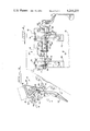
- FIG. 2 is an illustration of the major parts of the tilt steering column mechanism, with the omission of minor hardware for purpose of clarity;
- FIG. 3 is an enlarged side view of the tilt steering column with the handle in the locked position
- FIG. 4 is a partial sectional view of the tilt steering mechanism scanning in the general direction and between the arrows A and B in FIG. 3;
- FIG. 5 is similar to FIG. 3 but shows the handle in the unlocked position and the slider bracket means shifted to a new location
- FIG. 6 is similar to FIG. 4 but taken in the general direction of arrow C in FIG. 5.
- a tilt steering column mechanism is generally designated 10 in the various figures of the drawing.
- a conventional steering column assembly 15 is shown in one tilted position c in solid lines and in another tilted position b in phantom lines and includes a steering wheel 11, at the top of the steering column 12, the universal joint 13 at the base, and a two-piece steering column base housing 14.
- a stationary support bracket means 20 is fixed to the cab supported frame 16 and has three laterally spaced apart flanges 51, 54, 55 that extend forwardly and upwardly.
- the laterally spaced-apart flanges 51, 54, 55 have aligned co-axial bores corresponding in size to the various sizes of the slideable portions on the elongated locking bolt 22.
- Two spaced-apart anchor portions 23, 24 have sizes corresponding to the width of the slots 46,46 in the two identical slider bracket means 40,40, which may be constructed from one piece or in two pieces as shown, and anchor the slider bracket means 40,40 to the support bracket means 20.
- Two frusto-conical detent portion means 25, 26 taper downwardly into the two anchor portions 23, 24.
- the one frusto-conical portion 26, on the left outboard side of the locking bar 22, is sleeved over a threaded end portion of the locking bar 22, and is resiliently held in place by a pair of jam nuts 27 which abut against a flat disk washer 28, which in turn abuts against a spring washer 29, which abuts against the large side of the slideably mounted frusto-conical portion means 26.
- the opposite end of the locking bar 22 is connected to the operating handle 30 by means of a pin 34 and carries a cam follower pin means 60 which contacts the undulating land surface 67 of rotary cam means 61, which is slideably mounted in a cup 61 on the lateral side of flange 55.
- the cup 61 is provided with two axially extending slots 63 which cooperate with two lugs 64 on the circumference of the rotary cam means 61.
- Three identical spring washers 65 and a thrust ring washer 66 urge the undulated land surface 67 into contact with the cam follower pin means 60, which is keyed to the locking bar 22.
- the slider bracket means 40,40 comprise two identical slotted slider arm means 19,19, each of which have a pedestal fixed to a base 14 on the steering column 12.
- the arm means 19,19 pass forwardly and upwardly along side one flat lateral side of each of the three flange members 51, 54, 55 on the support bracket means 20. Since the slotted slider bracket arm means 19,19 are identical only the one on the right will be described in detail.
- An elongated slot 46 is provided in the projecting arm means 19 which respectively passes over the one right anchor portion 23 on the locking bar 22 and is anchored thereby to the two adjacent spaced-apart flanges 54 and 55 on the support bracket means 20.
- frusto-conical detent receiving holes 41, 42, 43, 44 taper downwardly into the slot 46 and each form a seat for the right frusto-conical detent portion 25 on the elongated locking bar 22.
- the indentical frusto-conical detent receiving holes in the left arm means 19 also, each form a seat for the left frusto-conical detent portion 26.
- a coil spring 50 of greater magnitude than the cluster of three spring washers 65 that act on the rotary cam means 61, is sleeved over the mid-section of the rod 22 between the left outer and inner flanges 51, 54 and is compressed against a thrust washer 68, which abuts the inner flange 54 and a flat washer 52 which is anchored to the locking bar 22 by a snap ring 53 seated in a groove provided in the locking bar 22.
- the cam follower pin means 60 when seated in the notch 69 provided on the raised land cam surface 67 compresses the cluster of three spring washers 65 and the spring 50 and firmly seats the cylindrical body of the rotary cam means 61 in the cup 62 and both frusto-conical detent portion means 25, 26 in the one selected axially aligned pair of frusto-conical holes 41, 42, 43 or 44 in the two arm means 19,19 and also compresses the coil spring 50 and the spring washer 29 on the threaded end of the locking bar 22.
- handle 30 In order to pivot the steering wheel 11 to any one of the three other tilted positions a, b, or d, from the c position shown in FIG. 1, handle 30 is pulled rearwardly or rotated counterclockwise from the engaged or locked position shown in FIG. 3, to the disengaged or unlocked position shown in FIG. 5.
- the cam follower pin means 60 rides downwardly on the falling land cam surface 67 releasing the pressure or loading on all three spring means 29, 50, 65.
- the one spring means 50 together with the second spring means 29, push against the locking bar 22 thereby shifting the locking bar 22 to the left against the action of the third spring means 65 until both frusto-conical detent portion means 24, 25 are each unseated from their respective frusto-conical detent receiving holes 41 in the two indentical slider bracket arm means 19,19 and the rotary cam means 61 is shifted to the right towards the arm of the cup 62 and is prevented from rotating by the lugs 64 in the track slots 63.
- the driver or operator now pivots or tilts the steering column 12 to the selected new position, for instance to the dash line b position of FIG. 1, about the axis of the universal connection 13.
- the slot 46 in each of the slider bracket arm means 19,19 slides over the respective anchor portions 23, 24 on the locking bar 22, thereby permitting the slider bracket arm means 19,19 to slide rearwardly alongside the one flat lateral side of each of the flanges 51, 54, 55 on the base 18 of the support bracket means 20 and axially align the frusto-conical detent portion means 25, 26 with the one pair of frusto-conical detent receiving holes 44 corresponding to the selected b position of the steering column 12.
Landscapes
- Engineering & Computer Science (AREA)
- Chemical & Material Sciences (AREA)
- Combustion & Propulsion (AREA)
- Transportation (AREA)
- Mechanical Engineering (AREA)
- Steering Controls (AREA)
Abstract
Description
Claims (7)
Priority Applications (1)
| Application Number | Priority Date | Filing Date | Title |
|---|---|---|---|
| US06/042,746 US4244237A (en) | 1979-05-29 | 1979-05-29 | Tilt steering column mechanism |
Applications Claiming Priority (1)
| Application Number | Priority Date | Filing Date | Title |
|---|---|---|---|
| US06/042,746 US4244237A (en) | 1979-05-29 | 1979-05-29 | Tilt steering column mechanism |
Publications (1)
| Publication Number | Publication Date |
|---|---|
| US4244237A true US4244237A (en) | 1981-01-13 |
Family
ID=21923530
Family Applications (1)
| Application Number | Title | Priority Date | Filing Date |
|---|---|---|---|
| US06/042,746 Expired - Lifetime US4244237A (en) | 1979-05-29 | 1979-05-29 | Tilt steering column mechanism |
Country Status (1)
| Country | Link |
|---|---|
| US (1) | US4244237A (en) |
Cited By (52)
| Publication number | Priority date | Publication date | Assignee | Title |
|---|---|---|---|---|
| EP0058495A1 (en) * | 1981-02-13 | 1982-08-25 | Ford Motor Company Limited | Steering column assembly |
| US4488699A (en) * | 1981-01-21 | 1984-12-18 | Compagnie Industrielle De Mecanismes, En Abrege C.I.M. | Device for regulating the position of an element and in particular a vehicle seat structure |
| US4495834A (en) * | 1982-02-22 | 1985-01-29 | Clark Equipment Company | Adjustable steering column |
| US4518002A (en) * | 1982-11-08 | 1985-05-21 | Tubular Fabricators Ind., Inc. | Foldable walker with plunger actuated latch assembly |
| US4541298A (en) * | 1982-01-15 | 1985-09-17 | Ford Motor Company | Adjustable steering column mounting |
| US4640301A (en) * | 1982-11-08 | 1987-02-03 | Tubular Fabricators Industry, Inc. | Foldable walker with plunger actuated latch assembly |
| US4648624A (en) * | 1985-09-30 | 1987-03-10 | Cycles Peugeot | Fixing device for a tubular part, in particular for the steering column of a vehicle |
| EP0242928A1 (en) * | 1986-04-23 | 1987-10-28 | Volvo Car B.V. | Clamping mechanism for fixing a steering column housing |
| US4732050A (en) * | 1986-06-06 | 1988-03-22 | Daimler-Benz Aktiengesellschaft | Receiving arrangement for a steering column of a motor vehicle |
| AT386389B (en) * | 1982-02-04 | 1988-08-10 | Steyr Daimler Puch Ag | Steering column for motor vehicles having a hydraulic steering device |
| EP0411312A1 (en) * | 1989-08-03 | 1991-02-06 | Dr.Ing.h.c. F. Porsche Aktiengesellschaft | Device for locking an adjustable safety steering column of a motor vehicle |
| EP0443881A3 (en) * | 1990-02-23 | 1992-01-15 | Fuji Kiko Company Limited | Tilting steering column |
| EP0493181A1 (en) * | 1990-12-28 | 1992-07-01 | Ecia - Equipements Et Composants Pour L'industrie Automobile | Position lock for adjustable vehicle steering column |
| GB2259132A (en) * | 1991-08-27 | 1993-03-03 | Torrington Co | Locking device for adjustable steering column. |
| US5265492A (en) * | 1992-12-15 | 1993-11-30 | Chrysler Corporation | Handle-operated locking device for tilt steering column |
| FR2696404A1 (en) * | 1992-10-06 | 1994-04-08 | Ecia Equip Composants Ind Auto | Device for locking in position an adjustable steering column, in particular for a motor vehicle, and column assembly comprising such a device. |
| EP0600700A1 (en) * | 1992-12-02 | 1994-06-08 | The Torrington Company Limited | Steering column clamping mechanism |
| US5361646A (en) * | 1993-04-01 | 1994-11-08 | Trw Inc. | Locking mechanism |
| US5423572A (en) * | 1994-04-01 | 1995-06-13 | General Motors Corporation | Position control apparatus for steering column |
| GB2287773A (en) * | 1994-03-17 | 1995-09-27 | Torrington Co | Clamping mechanism for an adjustable steering column for a vehicle |
| US5461937A (en) * | 1994-10-31 | 1995-10-31 | General Motors Corporation | Position control apparatus for steering column |
| US5481938A (en) * | 1994-05-02 | 1996-01-09 | General Motors Corporation | Position control apparatus for steering column |
| US5941129A (en) * | 1997-07-21 | 1999-08-24 | General Motors Corporation | Clamp for motor vehicle steering column |
| US6021690A (en) * | 1997-05-15 | 2000-02-08 | Preh-Werke Gmbh & Co. Kg | Operational control |
| US6161982A (en) * | 1998-04-22 | 2000-12-19 | Splined Tools Corporation | Assembly with a sealed coupler |
| US6164152A (en) * | 1999-05-10 | 2000-12-26 | Nagle Industries, Inc. | Column tilt actuator assembly |
| US6301990B1 (en) * | 2000-03-14 | 2001-10-16 | Trw Inc. | Locking apparatus |
| US6450531B1 (en) | 2001-01-03 | 2002-09-17 | Daimlerchrysler Corporation | Anti-friction cam-operated friction disk clutch |
| US20030168843A1 (en) * | 2002-03-11 | 2003-09-11 | Ryne Patrik M. | Telescoping column having rake spring assist |
| US20030221505A1 (en) * | 2002-03-08 | 2003-12-04 | Timken U.S. Corporation | Steering column clamping device |
| US6840141B2 (en) | 2003-01-09 | 2005-01-11 | Brian T. Cole | Radial indexing head tool with floating splined pin |
| US20050145056A1 (en) * | 2003-12-08 | 2005-07-07 | Maida Robert D. | Tilt control lever assembly for steering column |
| US20050178231A1 (en) * | 2004-02-13 | 2005-08-18 | Timken U.S. Corporation | Steering column clamping device |
| US20050178249A1 (en) * | 2003-01-09 | 2005-08-18 | Cole Charles A. | Radial indexing head tool with floating splined pin |
| US20060021461A1 (en) * | 2002-05-13 | 2006-02-02 | Tetsuya Murakami | Vehicular steering apparatus |
| US7028579B2 (en) * | 2001-05-23 | 2006-04-18 | Nsk Steering Systems Europe Limited | Over-mold lever |
| US20060169087A1 (en) * | 2005-01-18 | 2006-08-03 | Delphi Technologies, Inc. | Tiltable steering column |
| US20060207378A1 (en) * | 2005-03-17 | 2006-09-21 | Delphi Technologies, Inc. | Mounting structure for steering column |
| US20060273567A1 (en) * | 2005-06-02 | 2006-12-07 | Vincent Fix | Locking module for locking a steering column and a corresponding steering column |
| US20070127982A1 (en) * | 2005-11-15 | 2007-06-07 | Daimlerchrysler Ag | Device for pivotably connecting at least two components and a method for mounting the device |
| US20080202275A1 (en) * | 2005-04-19 | 2008-08-28 | Delphi Technologies, Inc. | Electric steering column lock with single direction actuator travel |
| US20080202276A1 (en) * | 2005-04-19 | 2008-08-28 | Delphi Technologies, Inc. | Adjustable steering column assembly |
| US20090107278A1 (en) * | 2007-10-30 | 2009-04-30 | Vermeersch Michael C | Energy absorbing shift lever assembly with reusable latching mechanism |
| US20090205460A1 (en) * | 2006-01-09 | 2009-08-20 | Delphi Technologies, Inc. | Lock lever on steering column |
| US20090218800A1 (en) * | 2005-04-19 | 2009-09-03 | Delphi Technologies, Inc. | Steering column with rake and telescope adjustment |
| US20100019214A1 (en) * | 2008-07-21 | 2010-01-28 | Indexable Tools, LLC | Hammer and crowbar with adjustable claw |
| US20130174684A1 (en) * | 2012-01-11 | 2013-07-11 | International Truck Intellectual Property Company, Llc | Steering column adjustment |
| US20130192409A1 (en) * | 2012-01-26 | 2013-08-01 | Steering Solutions Ip Holding Corporation | Adjustable steering column assembly |
| US20150266497A1 (en) * | 2014-03-24 | 2015-09-24 | Jtekt Corporation | Steering device |
| US20150266499A1 (en) * | 2014-03-24 | 2015-09-24 | Jtekt Corporation | Steering device |
| US20160280247A1 (en) * | 2015-03-27 | 2016-09-29 | Fuji Kiko Co., Ltd. | Steering column device for absorbing impact energy |
| CN111731371A (en) * | 2020-06-19 | 2020-10-02 | 汉腾汽车有限公司 | An improved steering column adjustment handle mechanism |
Citations (5)
| Publication number | Priority date | Publication date | Assignee | Title |
|---|---|---|---|---|
| US2873822A (en) * | 1954-02-03 | 1959-02-17 | Cushman Chuck Co | Bolt-type locking mechanisms for indexing devices |
| US2936652A (en) * | 1958-07-17 | 1960-05-17 | Vlier Engineering Corp | Index plunger |
| CA853500A (en) * | 1970-10-13 | International Harvester Company | Tiltable steering wheel | |
| DE1949241A1 (en) * | 1969-09-30 | 1971-04-22 | Kloeckner Humboldt Deutz Ag | Steering device for motor vehicles |
| US3991633A (en) * | 1975-07-11 | 1976-11-16 | Caterpillar Tractor Co. | Adjustable steering column assembly |
-
1979
- 1979-05-29 US US06/042,746 patent/US4244237A/en not_active Expired - Lifetime
Patent Citations (5)
| Publication number | Priority date | Publication date | Assignee | Title |
|---|---|---|---|---|
| CA853500A (en) * | 1970-10-13 | International Harvester Company | Tiltable steering wheel | |
| US2873822A (en) * | 1954-02-03 | 1959-02-17 | Cushman Chuck Co | Bolt-type locking mechanisms for indexing devices |
| US2936652A (en) * | 1958-07-17 | 1960-05-17 | Vlier Engineering Corp | Index plunger |
| DE1949241A1 (en) * | 1969-09-30 | 1971-04-22 | Kloeckner Humboldt Deutz Ag | Steering device for motor vehicles |
| US3991633A (en) * | 1975-07-11 | 1976-11-16 | Caterpillar Tractor Co. | Adjustable steering column assembly |
Cited By (82)
| Publication number | Priority date | Publication date | Assignee | Title |
|---|---|---|---|---|
| US4488699A (en) * | 1981-01-21 | 1984-12-18 | Compagnie Industrielle De Mecanismes, En Abrege C.I.M. | Device for regulating the position of an element and in particular a vehicle seat structure |
| EP0058495A1 (en) * | 1981-02-13 | 1982-08-25 | Ford Motor Company Limited | Steering column assembly |
| US4541298A (en) * | 1982-01-15 | 1985-09-17 | Ford Motor Company | Adjustable steering column mounting |
| AT386389B (en) * | 1982-02-04 | 1988-08-10 | Steyr Daimler Puch Ag | Steering column for motor vehicles having a hydraulic steering device |
| US4495834A (en) * | 1982-02-22 | 1985-01-29 | Clark Equipment Company | Adjustable steering column |
| US4518002A (en) * | 1982-11-08 | 1985-05-21 | Tubular Fabricators Ind., Inc. | Foldable walker with plunger actuated latch assembly |
| US4640301A (en) * | 1982-11-08 | 1987-02-03 | Tubular Fabricators Industry, Inc. | Foldable walker with plunger actuated latch assembly |
| US4648624A (en) * | 1985-09-30 | 1987-03-10 | Cycles Peugeot | Fixing device for a tubular part, in particular for the steering column of a vehicle |
| EP0242928A1 (en) * | 1986-04-23 | 1987-10-28 | Volvo Car B.V. | Clamping mechanism for fixing a steering column housing |
| US4788880A (en) * | 1986-04-23 | 1988-12-06 | Volvo Car B.V. | Clamping mechanism for fixing a steering column housing |
| US4732050A (en) * | 1986-06-06 | 1988-03-22 | Daimler-Benz Aktiengesellschaft | Receiving arrangement for a steering column of a motor vehicle |
| US5064219A (en) * | 1989-08-03 | 1991-11-12 | Dr. Ing. H.C.F. Porsche Ag | Arrangement for locking an adjustable safety steering column for motor vehicles |
| EP0411312A1 (en) * | 1989-08-03 | 1991-02-06 | Dr.Ing.h.c. F. Porsche Aktiengesellschaft | Device for locking an adjustable safety steering column of a motor vehicle |
| EP0443881A3 (en) * | 1990-02-23 | 1992-01-15 | Fuji Kiko Company Limited | Tilting steering column |
| US5117707A (en) * | 1990-02-23 | 1992-06-02 | Fuji Kiko Company, Limited | Tilting steering column |
| US5213004A (en) * | 1990-12-28 | 1993-05-25 | Ecia | Device for locking in position the adjustable steering column of a motor vehicle |
| FR2671040A1 (en) * | 1990-12-28 | 1992-07-03 | Ecia Equip Composants Ind Auto | LOCKING DEVICE IN THE POSITION OF AN ADJUSTABLE STEERING COLUMN OF A MOTOR VEHICLE. |
| EP0493181A1 (en) * | 1990-12-28 | 1992-07-01 | Ecia - Equipements Et Composants Pour L'industrie Automobile | Position lock for adjustable vehicle steering column |
| GB2259132A (en) * | 1991-08-27 | 1993-03-03 | Torrington Co | Locking device for adjustable steering column. |
| US5213003A (en) * | 1991-08-27 | 1993-05-25 | The Torrington Company | Locking device for an adjustable steering column assembly |
| US5394767A (en) * | 1992-10-06 | 1995-03-07 | Ecia-Equipements Et Composants Pour L'industrie Automobile | Device for locking in position an adjustable steering column for a motor vehicle |
| FR2696404A1 (en) * | 1992-10-06 | 1994-04-08 | Ecia Equip Composants Ind Auto | Device for locking in position an adjustable steering column, in particular for a motor vehicle, and column assembly comprising such a device. |
| EP0592278A1 (en) * | 1992-10-06 | 1994-04-13 | Ecia - Equipements Et Composants Pour L'industrie Automobile | Device for locking an adjustable steering column for example of an automotive vehicle and steering column unit comprising such a device |
| EP0600700A1 (en) * | 1992-12-02 | 1994-06-08 | The Torrington Company Limited | Steering column clamping mechanism |
| AU661798B2 (en) * | 1992-12-02 | 1995-08-03 | Torrington Company Limited, The | Steering column clamping mechanism |
| US5377555A (en) * | 1992-12-02 | 1995-01-03 | The Torrington Company | Steering column clamping mechanism |
| US5265492A (en) * | 1992-12-15 | 1993-11-30 | Chrysler Corporation | Handle-operated locking device for tilt steering column |
| US5361646A (en) * | 1993-04-01 | 1994-11-08 | Trw Inc. | Locking mechanism |
| GB2287773A (en) * | 1994-03-17 | 1995-09-27 | Torrington Co | Clamping mechanism for an adjustable steering column for a vehicle |
| US5598741A (en) * | 1994-03-17 | 1997-02-04 | The Torrington Company | Clamping mechanism for an adjustable steering column for a vehicle |
| US5423572A (en) * | 1994-04-01 | 1995-06-13 | General Motors Corporation | Position control apparatus for steering column |
| US5481938A (en) * | 1994-05-02 | 1996-01-09 | General Motors Corporation | Position control apparatus for steering column |
| US5461937A (en) * | 1994-10-31 | 1995-10-31 | General Motors Corporation | Position control apparatus for steering column |
| US6021690A (en) * | 1997-05-15 | 2000-02-08 | Preh-Werke Gmbh & Co. Kg | Operational control |
| US5941129A (en) * | 1997-07-21 | 1999-08-24 | General Motors Corporation | Clamp for motor vehicle steering column |
| US6161982A (en) * | 1998-04-22 | 2000-12-19 | Splined Tools Corporation | Assembly with a sealed coupler |
| US6164152A (en) * | 1999-05-10 | 2000-12-26 | Nagle Industries, Inc. | Column tilt actuator assembly |
| US6301990B1 (en) * | 2000-03-14 | 2001-10-16 | Trw Inc. | Locking apparatus |
| US6450531B1 (en) | 2001-01-03 | 2002-09-17 | Daimlerchrysler Corporation | Anti-friction cam-operated friction disk clutch |
| US7028579B2 (en) * | 2001-05-23 | 2006-04-18 | Nsk Steering Systems Europe Limited | Over-mold lever |
| US7010996B2 (en) | 2002-03-08 | 2006-03-14 | Timken Us Corporation | Steering column clamping device |
| US20030221505A1 (en) * | 2002-03-08 | 2003-12-04 | Timken U.S. Corporation | Steering column clamping device |
| US20030168843A1 (en) * | 2002-03-11 | 2003-09-11 | Ryne Patrik M. | Telescoping column having rake spring assist |
| US6923473B2 (en) * | 2002-03-11 | 2005-08-02 | Delphi Technologies, Inc. | Telescoping column having rake spring assist |
| US7328631B2 (en) | 2002-05-13 | 2008-02-12 | Koyo Seiko Co., Ltd. | Vehicular steering apparatus |
| US7353727B2 (en) * | 2002-05-13 | 2008-04-08 | Koyo Seiko Co., Ltd. | Vehicular steering apparatus |
| US20060021461A1 (en) * | 2002-05-13 | 2006-02-02 | Tetsuya Murakami | Vehicular steering apparatus |
| US20060022446A1 (en) * | 2002-05-13 | 2006-02-02 | Tetsuya Murakami | Vehicular steering apparatus |
| US6840141B2 (en) | 2003-01-09 | 2005-01-11 | Brian T. Cole | Radial indexing head tool with floating splined pin |
| US20050178249A1 (en) * | 2003-01-09 | 2005-08-18 | Cole Charles A. | Radial indexing head tool with floating splined pin |
| US7156003B2 (en) | 2003-01-09 | 2007-01-02 | Cole Charles A | Radial indexing head tool with floating splined pin |
| US7263910B2 (en) | 2003-12-08 | 2007-09-04 | Delphi Technologies, Inc. | Tilt control lever assembly for steering column |
| US20050145056A1 (en) * | 2003-12-08 | 2005-07-07 | Maida Robert D. | Tilt control lever assembly for steering column |
| US20050178231A1 (en) * | 2004-02-13 | 2005-08-18 | Timken U.S. Corporation | Steering column clamping device |
| US20060169087A1 (en) * | 2005-01-18 | 2006-08-03 | Delphi Technologies, Inc. | Tiltable steering column |
| US7475614B2 (en) | 2005-01-18 | 2009-01-13 | Delphi Technologies, Inc. | Tiltable steering column |
| US20060207378A1 (en) * | 2005-03-17 | 2006-09-21 | Delphi Technologies, Inc. | Mounting structure for steering column |
| US20080202276A1 (en) * | 2005-04-19 | 2008-08-28 | Delphi Technologies, Inc. | Adjustable steering column assembly |
| US20080202275A1 (en) * | 2005-04-19 | 2008-08-28 | Delphi Technologies, Inc. | Electric steering column lock with single direction actuator travel |
| US8220355B2 (en) | 2005-04-19 | 2012-07-17 | Steering Solutions Ip Holding Corporation | Electric steering column lock with single direction actuator travel |
| US20090218800A1 (en) * | 2005-04-19 | 2009-09-03 | Delphi Technologies, Inc. | Steering column with rake and telescope adjustment |
| US7861615B2 (en) * | 2005-04-19 | 2011-01-04 | Gm Global Technology Operations, Inc. | Adjustable steering column assembly |
| US8056437B2 (en) | 2005-04-19 | 2011-11-15 | Nexteer (Beijing) Technology Co., Ltd. | Electric steering column lock with single direction actuator travel |
| US8201475B2 (en) | 2005-04-19 | 2012-06-19 | Steering Solutions Ip Holding Corporation | Steering column with rake and telescope adjustment |
| US20060273567A1 (en) * | 2005-06-02 | 2006-12-07 | Vincent Fix | Locking module for locking a steering column and a corresponding steering column |
| US20070127982A1 (en) * | 2005-11-15 | 2007-06-07 | Daimlerchrysler Ag | Device for pivotably connecting at least two components and a method for mounting the device |
| US20090205460A1 (en) * | 2006-01-09 | 2009-08-20 | Delphi Technologies, Inc. | Lock lever on steering column |
| US8960050B2 (en) * | 2006-01-09 | 2015-02-24 | Steering Solutions Ip Holding Corporation | Lock lever on steering column |
| US20090107278A1 (en) * | 2007-10-30 | 2009-04-30 | Vermeersch Michael C | Energy absorbing shift lever assembly with reusable latching mechanism |
| US8677851B2 (en) | 2007-10-30 | 2014-03-25 | Steering Solutions Ip Holding Corporation | Energy absorbing shift lever assembly with reusable latching mechanism |
| US8424845B2 (en) | 2008-07-21 | 2013-04-23 | Indexable Tools, LLC | Hammer and crowbar with adjustable claw |
| US20100019214A1 (en) * | 2008-07-21 | 2010-01-28 | Indexable Tools, LLC | Hammer and crowbar with adjustable claw |
| US20130174684A1 (en) * | 2012-01-11 | 2013-07-11 | International Truck Intellectual Property Company, Llc | Steering column adjustment |
| US20130192409A1 (en) * | 2012-01-26 | 2013-08-01 | Steering Solutions Ip Holding Corporation | Adjustable steering column assembly |
| US9527521B2 (en) * | 2012-01-26 | 2016-12-27 | Steering Solutions Ip Holding Corporation | Adjustable steering column assembly |
| US20150266499A1 (en) * | 2014-03-24 | 2015-09-24 | Jtekt Corporation | Steering device |
| US9242667B2 (en) * | 2014-03-24 | 2016-01-26 | Jtekt Corporation | Steering device |
| US9327755B2 (en) * | 2014-03-24 | 2016-05-03 | Jtekt Corporation | Steering device |
| US20150266497A1 (en) * | 2014-03-24 | 2015-09-24 | Jtekt Corporation | Steering device |
| US20160280247A1 (en) * | 2015-03-27 | 2016-09-29 | Fuji Kiko Co., Ltd. | Steering column device for absorbing impact energy |
| US9623896B2 (en) * | 2015-03-27 | 2017-04-18 | Fuji Kiko Co., Ltd. | Steering column device for absorbing impact energy |
| CN111731371A (en) * | 2020-06-19 | 2020-10-02 | 汉腾汽车有限公司 | An improved steering column adjustment handle mechanism |
Similar Documents
| Publication | Publication Date | Title |
|---|---|---|
| US4244237A (en) | Tilt steering column mechanism | |
| US4830434A (en) | Adjustable head rest device for vehicle | |
| US6027170A (en) | Rotating vehicle seat | |
| US4384744A (en) | Seat reclining mechanism | |
| US5466048A (en) | Backrest release mechanism | |
| US6012755A (en) | Foldable automotive seat | |
| EP0094221B1 (en) | Variable back adjustor for chairs | |
| US4507982A (en) | Steering column assembly | |
| US4008920A (en) | Seat back adjuster | |
| US4244236A (en) | Tilt steering column mechanism | |
| US4889386A (en) | Rear seat for motor vehicles | |
| US4624437A (en) | Body-weight adjusting device of a seat suspension | |
| CA2195088A1 (en) | Infinitely adjustable linear actuator | |
| US4033158A (en) | Adjustable steering wheel and transmission lock arrangement | |
| US4611783A (en) | Body-weight adjusting device of a seat suspension | |
| EP1299260B1 (en) | Compact recliner assembly for a vehicle seat | |
| US4384743A (en) | Adjustable stop assembly for limiting the recline angle of a seat back | |
| USH2129H1 (en) | Disc recliner assembly with fold-flat latch link mechanism | |
| US6527342B2 (en) | Cone recliner/clutch mechanism | |
| US4245866A (en) | Linear control for reclining seat | |
| US6957853B2 (en) | Vehicle seating apparatus | |
| US5282394A (en) | Low pivot steering column tilt mechanism | |
| US4417648A (en) | Braking arrangement for vehicles | |
| JPH07112794B2 (en) | Brake vedal device for unlocking gear shift lever of automobile | |
| EP0425237A2 (en) | Reclining device for automotive seat |
Legal Events
| Date | Code | Title | Description |
|---|---|---|---|
| AS | Assignment |
Owner name: FIDELITY UNION BANK, TRUSTEE Free format text: SECURITY INTEREST;ASSIGNOR:INTERNATIONAL HARVESTER COMPANY;REEL/FRAME:003970/0963 Effective date: 19811101 Owner name: PATTERSON, LINDA L., TRUSTEE Free format text: SECURITY INTEREST;ASSIGNOR:INTERNATIONAL HARVESTER COMPANY;REEL/FRAME:003970/0963 Effective date: 19811101 Owner name: FIDELITY UNION BANK, TRUSTEE, ILLINOIS Free format text: SECURITY INTEREST;ASSIGNOR:INTERNATIONAL HARVESTER COMPANY;REEL/FRAME:003970/0963 Effective date: 19811101 Owner name: PATTERSON, LINDA L., TRUSTEE, ILLINOIS Free format text: SECURITY INTEREST;ASSIGNOR:INTERNATIONAL HARVESTER COMPANY;REEL/FRAME:003970/0963 Effective date: 19811101 |
|
| AS | Assignment |
Owner name: NAVISTAR INTERNATIONAL CORPORATION Free format text: CHANGE OF NAME;ASSIGNOR:INTERNATIONAL HARVESTER COMPANY;REEL/FRAME:004546/0650 Effective date: 19860220 Owner name: NAVISTAR INTERNATIONAL CORPORATION, ILLINOIS Free format text: CHANGE OF NAME;ASSIGNOR:INTERNATIONAL HARVESTER COMPANY;REEL/FRAME:004546/0650 Effective date: 19860220 |
|
| AS | Assignment |
Owner name: NAVISTAR INTERNATIONAL CORPORATION, 401 NORTH MICH Free format text: ASSIGNMENT OF ASSIGNORS INTEREST.;ASSIGNOR:FIRST FIDELITY BANK, NATIONAL ASSOCIATION, NEW JERSEY;REEL/FRAME:004662/0693 Effective date: 19861230 Owner name: NAVISTAR INTERNATIONAL CORPORATION, A CORP OF DE., Free format text: ASSIGNMENT OF ASSIGNORS INTEREST;ASSIGNOR:FIRST FIDELITY BANK, NATIONAL ASSOCIATION, NEW JERSEY;REEL/FRAME:004662/0693 Effective date: 19861230 |
|
| AS | Assignment |
Owner name: NAVISTAR INTERNATIONAL CORPORATION A CORP. OF DE, Free format text: MERGER;ASSIGNOR:NAVISTAR INTERNATIONAL TRANSPORTATION CORP. (MERGED);REEL/FRAME:005195/0610 Effective date: 19870317 |