US423553A - Alternating-current electric regulator - Google Patents
Alternating-current electric regulator Download PDFInfo
- Publication number
- US423553A US423553A US423553DA US423553A US 423553 A US423553 A US 423553A US 423553D A US423553D A US 423553DA US 423553 A US423553 A US 423553A
- Authority
- US
- United States
- Prior art keywords
- coils
- coil
- circuit
- alternating
- block
- Prior art date
- Legal status (The legal status is an assumption and is not a legal conclusion. Google has not performed a legal analysis and makes no representation as to the accuracy of the status listed.)
- Expired - Lifetime
Links
- 230000000694 effects Effects 0.000 description 3
- 230000008859 change Effects 0.000 description 2
- 230000009467 reduction Effects 0.000 description 2
- 230000001105 regulatory effect Effects 0.000 description 2
- 230000009471 action Effects 0.000 description 1
- 230000004075 alteration Effects 0.000 description 1
- 239000004020 conductor Substances 0.000 description 1
- 230000001939 inductive effect Effects 0.000 description 1
- 230000007246 mechanism Effects 0.000 description 1
- 239000002184 metal Substances 0.000 description 1
Images

Classifications
-
- G—PHYSICS
- G01—MEASURING; TESTING
- G01V—GEOPHYSICS; GRAVITATIONAL MEASUREMENTS; DETECTING MASSES OR OBJECTS; TAGS
- G01V3/00—Electric or magnetic prospecting or detecting; Measuring magnetic field characteristics of the earth, e.g. declination, deviation
- G01V3/08—Electric or magnetic prospecting or detecting; Measuring magnetic field characteristics of the earth, e.g. declination, deviation operating with magnetic or electric fields produced or modified by objects or geological structures or by detecting devices
- G01V3/10—Electric or magnetic prospecting or detecting; Measuring magnetic field characteristics of the earth, e.g. declination, deviation operating with magnetic or electric fields produced or modified by objects or geological structures or by detecting devices using induction coils
-
- H—ELECTRICITY
- H02—GENERATION; CONVERSION OR DISTRIBUTION OF ELECTRIC POWER
- H02M—APPARATUS FOR CONVERSION BETWEEN AC AND AC, BETWEEN AC AND DC, OR BETWEEN DC AND DC, AND FOR USE WITH MAINS OR SIMILAR POWER SUPPLY SYSTEMS; CONVERSION OF DC OR AC INPUT POWER INTO SURGE OUTPUT POWER; CONTROL OR REGULATION THEREOF
- H02M5/00—Conversion of AC power input into AC power output, e.g. for change of voltage, for change of frequency, for change of number of phases
- H02M5/02—Conversion of AC power input into AC power output, e.g. for change of voltage, for change of frequency, for change of number of phases without intermediate conversion into DC
- H02M5/04—Conversion of AC power input into AC power output, e.g. for change of voltage, for change of frequency, for change of number of phases without intermediate conversion into DC by static converters
- H02M5/06—Conversion of AC power input into AC power output, e.g. for change of voltage, for change of frequency, for change of number of phases without intermediate conversion into DC by static converters using impedances
- H02M5/08—Conversion of AC power input into AC power output, e.g. for change of voltage, for change of frequency, for change of number of phases without intermediate conversion into DC by static converters using impedances using capacitors only
Definitions
- This pressure-compensator has for its object to cause any change of pressure and current required in any work-circuit to be elfected at the sourceviz., in the generating or inducing apparatus itself-without necessitating the interposition of regulating devices and without cutting out or introducing of any coils into the circuit.
- Thenovelty of regulation consists in a subdivision of coils and the provision of means for changing the relationship of the various subdivisions. The length chosen is such as to be fully capable of supplying the necessary pressure for the translating devices in circuit with it, and in this case all subdivisions are connected in series.
- means are provided to place one or more of said subdivisions in parallel with the rest, whereby the pressure is reduced without the removal of any coil, or else to still further reduce the pressure.
- the connections of the coil may be placed in parallel with the others, or else any other subdivision may be reversed, and then this reversed coil will act in opposition to the rest, with the effect of still further reducing the pressure compared with acoil connected in parallel.
- the means to make these changes are various. It may be acommutator or a re versing-switch, or a combination of reversingswitches, or connection or pole-changers in one single apparatus.
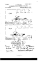
- Figure 1 represents a converter provided and connected with this regulating device.
- Figs. 2, 3, and 4 are diagram-connections, showing the different relationships between the coils.
- Fig; 5 is a simple reversing-switch.
- A is a generator of altern atin g, pulsating, or intermittent currents.
- B is a converter connected thereto.
- 0 is the primary coil of said converter.
- D is the secondary coil.
- E are pole-changers; F F, the
- G are translating devices in circuit with circuits F F.
- I) is the main part of the secondary coil.
- E are pole-changers in circuit with said coils.
- I" 11 are contact-blocks connected to terminals'of the coils of a converter.
- K and L are subdivisions of the secondary coil.
- M, N, and O are contacts on a movable slide R.
- P P are terminals of the circuit and of the converter-coil D.
- S is a reversing-switch.
- T, U, and V are contact-points of the switch.
- W W are contact-levers of switch.
- X X are terminals of neighboring secondary coils of the 0011- verter.
- Fig. 1 the primary coil of the converter B is connected in multiple arc with a generator of alternating, pulsating, or intermittent currents, and the secondary coil D is connected to the distributing or work line F F, in which the translating devices G are operated. length of wire as to be fully'capable of supplying the necessary pressure.
- the total length of coil D is. subdivided, andthe subdivisions connected to one another by means of grouping switches or pole-changers E. If the full pressure is required, then the changers E are so placed that the coils form a single series, asif they werewound of an uninterrupted wire.
- translating devices G represent lamps of which the brightness is desired to be lowered
- the secondary coil D has such a that the changes can be either effected, first,
- Figs. 2, 3, and I show clearly the means for operation and changing of connection and regulation without any of the coils or subdivisions needing to change place or to be cut out of circuit.
- the ends of coils D are connected to line F F at the points P P.
- the ends of the subdivisions are joined to contact blocks H H H H in such a manner that the left two blocks H and H are the terminals of the two starting-wires of the subcoils K and L,while blocks H and H are the terminals of the other ends of the coils K and L.
- a slide R on which are mounted several metal pieces electrically insulated from one another. These pieces are M, N, and O.
- coil D is connected to the work-circuit F F, in which translating devices are connected, and the current would flow from coil D to block H, subcoil K, block H, block M on slide R, block H, sub-coil L, block H block N, terminal P, line F, translating devices G, line F, and back to D, or vice versa, the current being alternating.
- This is the normal position or that for maximum pressure.
- Fig. 3 shows the connections of the first reduction in pressure.
- sub-coil K and sub-coil L are joined in parallel through H and N O.
- the current would flow from coil D (to block ll, block M of slide, and block H) at the same time, then to both sub-coils K and L, to blocks H and H, to blocks 0 and N on slide R, to terminal P, to line F, to translating devices G, line F, and back to coil D, or vice versa.
- the slide is advanced still farther, as shown in Fig. at.
- block N and block 0 of the slide do not touch the same contact-block as before, and the current flows now from coil D to block H, sub-coil K, block H, block 0 of slide,block H subcoil L, block H, block N of slide, terminal P, line F, translating devices G, line F, and back to D, or vice versa.
- L is now reversed or connected in opposition to coil K, and the work done by coil Lin this position is equivalent to cutting outtwo coils.
- the motion of the slide R is a rectilinear one; but if arranged in a circle or to rotate, the whole mechanism may be arranged into a small commutator.
- Fig. 5 shows the connection of one of the sub-coils K with a reversing-switch.
- the subcoil K is connected to three contact-points T, U, and V. One end is connected to contactpoint T, the other end to contact-point U, and a third connection is eifected from contactT to contact V.
- At the terminals X X are connected the endsof the neighboring coils D and L.
- an electric converter whose primary coils are included in a supply-circuit and whose secondary coil is subdivided, and the subdivisions thereof permanentlyincluded in a workcircuit and connected together by pole-changers.
- an alternating-electriccurrent regulator the combination of an electric converter, secondary coils therefor of different lengths, the shortest coils being connected among one another and to the large coils by pole-changers, and the larger coils being connected to contact-blocks, and all of said coils being included in a work-circuit.
- a primary and secondary coil wound thereon and each subdivided, the subdivisions of the two coils being connected electrically to one another by pole-changers, and the subdivisions of the primary coil being included in the supply-circuit and of the secondary in the work-circuit.
Landscapes
- Engineering & Computer Science (AREA)
- Physics & Mathematics (AREA)
- Remote Sensing (AREA)
- Life Sciences & Earth Sciences (AREA)
- Electromagnetism (AREA)
- Environmental & Geological Engineering (AREA)
- Geology (AREA)
- General Life Sciences & Earth Sciences (AREA)
- General Physics & Mathematics (AREA)
- Geophysics (AREA)
- Power Engineering (AREA)
- Keying Circuit Devices (AREA)
Description
(No Model.) 2 Sheets-Sheet 1.
L. GUTMANN. ALTERNATING CURRENT ELECTRIC REGULATOR.
Patented Mar. 18, 1890.
no Model.) w
L. GUTMANN. ALTBRNATING CURRENT ELEGTRIG REGULATOR.
P'a tented Mar. 18, 1890.
UNITED STATES PATENT OFFICE.
LUDWIG GUTMANN, OF FORT IVAYNE, INDIANA.
ALTERNATlNG-CURRENT ELECTRIC REGULATOR.
SPECIFICATION forming part of Letters Patent No. 423,553, dated March 18, 1890.
Application filed March 2, 1889. Serial No. 301,802. (No model.)
To all whom it may concern.-
Be it known that I, LUDWIG GUTMANN, a subject of the Emperor of Germany, and a resident of Fort WVayn e, in the county of Allen and State of Indiana, have invented certain new and useful Improvements in Alternating-Electric-Current Regulators, (Case 26,) of which the following is a specification.
This pressure-compensator has for its object to cause any change of pressure and current required in any work-circuit to be elfected at the sourceviz., in the generating or inducing apparatus itself-without necessitating the interposition of regulating devices and without cutting out or introducing of any coils into the circuit. Thenovelty of regulation consists in a subdivision of coils and the provision of means for changing the relationship of the various subdivisions. The length chosen is such as to be fully capable of supplying the necessary pressure for the translating devices in circuit with it, and in this case all subdivisions are connected in series. If it is desired to decrease the pressure, means are provided to place one or more of said subdivisions in parallel with the rest, whereby the pressure is reduced without the removal of any coil, or else to still further reduce the pressure. The connections of the coilmay be placed in parallel with the others, or else any other subdivision may be reversed, and then this reversed coil will act in opposition to the rest, with the effect of still further reducing the pressure compared with acoil connected in parallel. The means to make these changes are various. It may be acommutator or a re versing-switch, or a combination of reversingswitches, or connection or pole-changers in one single apparatus.
In the accompanying figures, Figure 1 represents a converter provided and connected with this regulating device. Figs. 2, 3, and 4 are diagram-connections, showing the different relationships between the coils. Fig; 5 is a simple reversing-switch.
In Figs. 1, 2, 3, and 4, A is a generator of altern atin g, pulsating, or intermittent currents. B is a converter connected thereto. 0 is the primary coil of said converter. D is the secondary coil. E are pole-changers; F F, the
work or distributing circuit. G are translating devices in circuit with circuits F F. I) is the main part of the secondary coil. E are pole-changers in circuit with said coils. H H
II" 11 are contact-blocks connected to terminals'of the coils of a converter. K and L are subdivisions of the secondary coil. M, N, and O are contacts on a movable slide R. P P are terminals of the circuit and of the converter-coil D.
In Fig. 5, S is a reversing-switch. T, U, and V are contact-points of the switch. W W are contact-levers of switch. X X are terminals of neighboring secondary coils of the 0011- verter.
In Fig. 1 the primary coil of the converter B is connected in multiple arc with a generator of alternating, pulsating, or intermittent currents, and the secondary coil D is connected to the distributing or work line F F, in which the translating devices G are operated. length of wire as to be fully'capable of supplying the necessary pressure. The total length of coil D is. subdivided, andthe subdivisions connected to one another by means of grouping switches or pole-changers E. If the full pressure is required, then the changers E are so placed that the coils form a single series, asif they werewound of an uninterrupted wire.
If translating devices G represent lamps of which the brightness is desired to be lowered, I operate one or more changers E to efiect the desired alteration by placing one or more of the sub-coils in parallel with one another, and should the reduction required have to be greater still, then I turn or advance changer E still more, whereby the connections of one or more sub-coils are reversed and react against the remaining part of the coil D.
It may be conveniently mentioned here The secondary coil D has such a that the changes can be either effected, first,
effect of those changes would be to cause them to run slower. It is evident that this means of varying the pressure and current is not only applicable to converters, but also choking magnets, motors, and generators.
Figs. 2, 3, and I show clearly the means for operation and changing of connection and regulation without any of the coils or subdivisions needing to change place or to be cut out of circuit. The ends of coils D are connected to line F F at the points P P. The ends of the subdivisions are joined to contact blocks H H H H in such a manner that the left two blocks H and H are the terminals of the two starting-wires of the subcoils K and L,while blocks H and H are the terminals of the other ends of the coils K and L. In contact with blocks H, H, H, and H is a slide R, on which are mounted several metal pieces electrically insulated from one another. These pieces are M, N, and O. In Fig. 2 it will be noticed that coil D is connected to the work-circuit F F, in which translating devices are connected, and the current would flow from coil D to block H, subcoil K, block H, block M on slide R, block H, sub-coil L, block H block N, terminal P, line F, translating devices G, line F, and back to D, or vice versa, the current being alternating. This is the normal position or that for maximum pressure.
Fig. 3 shows the connections of the first reduction in pressure. Here it will be noticed that sub-coil K and sub-coil L are joined in parallel through H and N O. In this position of slide R the current would flow from coil D (to block ll, block M of slide, and block H) at the same time, then to both sub-coils K and L, to blocks H and H, to blocks 0 and N on slide R, to terminal P, to line F, to translating devices G, line F, and back to coil D, or vice versa. ,To effect a still greater re duction in pressure, the slide is advanced still farther, as shown in Fig. at. In this case block N and block 0 of the slide do not touch the same contact-block as before, and the current flows now from coil D to block H, sub-coil K, block H, block 0 of slide,block H subcoil L, block H, block N of slide, terminal P, line F, translating devices G, line F, and back to D, or vice versa. It will be noticed that L is now reversed or connected in opposition to coil K, and the work done by coil Lin this position is equivalent to cutting outtwo coils. In these sketches the motion of the slide R is a rectilinear one; but if arranged in a circle or to rotate, the whole mechanism may be arranged into a small commutator.
Fig. 5 shows the connection of one of the sub-coils K with a reversing-switch. The subcoil K is connected to three contact-points T, U, and V. One end is connected to contactpoint T, the other end to contact-point U, and a third connection is eifected from contactT to contact V. At the terminals X X are connected the endsof the neighboring coils D and L.
In the connection shown in sketch the subcoil K is inclosed normally in the same direction in the circuit; but when the switch-levers \V \V are placed in the position indicated by the dotted lines making contact with U and V, then the connection, and therefore, also, the action of sub-coil K, is reversed. The changes described and explained with the secondary coil are not restricted to this coil, and can just as well be applied to the primary coil of a converter.
I claim as my invention- 1. In an alternating-current regulator, the combination of an electric converter whose primary coils are included in a supply-circuit and whose secondary coil is subdivided, and the subdivisions thereof permanentlyincluded in a workcircuit and connected together by pole-changers.
2. In an alternating-electriccurrent regulator, the combination of an electric converter, secondary coils therefor of different lengths, the shortest coils being connected among one another and to the large coils by pole-changers, and the larger coils being connected to contact-blocks, and all of said coils being included in a work-circuit.
3. I11 a converter, the combination of acore,
a primary and secondary coil wound thereon, and each subdivided, the subdivisions of the two coils being connected electrically to one another by pole-changers, and the subdivisions of the primary coil being included in the supply-circuit and of the secondary in the work-circuit.
4. In a converter, the combination of a secondary and primary coil, a core common to both, the primary coil being included in a supply-circuit and the secondary being subdivided, the subdivisions being included in a work-circuit and permanently connected to one another by pole-changers.
5. The combination of multiple secondary coils of a converter, all the coils being connected permanently in a work-circuit, and permanently connected to one another by pole-changers.
6. The combination, in an electric converter, of a subdivided coil, and pole-changers connected in circuit with subdivisions of said coil.
'7. In an alternating-ciu'rent regulator, the combination of secondary coils, with polechangers connecting together the coils, a work-circuit, and electrical connections between said coils and said work-circuit.
8. In a converter, the combination of a work-circuit, a primary coil, secondary coils in series and connected to said work-circuit, and pole-changers bet-ween and connected to the said coils.
9. In an alternating-electric-current regulator, the combination of a work-circuit, sec- IIO ondary coils of an electric converter, polemy invention I have signed my name in preschangers connecting the coils together in seence of two witnesses, this 2361 day of Februries, and means, such as electric conductors, ary, 1889.
for maintaining electric connection between LUDWVIG GrU'IMANN 5 the remaining terminals of the coils and those \Vitnesses:
of the said work-circuit. Y WILLIAM 0. RYAN,
In testimony that I claim the foregoing as T. L'KELLEY.
Publications (1)
| Publication Number | Publication Date |
|---|---|
| US423553A true US423553A (en) | 1890-03-18 |
Family
ID=2492468
Family Applications (1)
| Application Number | Title | Priority Date | Filing Date |
|---|---|---|---|
| US423553D Expired - Lifetime US423553A (en) | Alternating-current electric regulator |
Country Status (1)
| Country | Link |
|---|---|
| US (1) | US423553A (en) |
-
0
- US US423553D patent/US423553A/en not_active Expired - Lifetime
Similar Documents
| Publication | Publication Date | Title |
|---|---|---|
| US423553A (en) | Alternating-current electric regulator | |
| US742926A (en) | Potential-regulator for alternating-current circuits. | |
| US2205476A (en) | Transforming apparatus | |
| US386956A (en) | Reginald belfield | |
| US669362A (en) | Regulating device for electric currents. | |
| US740447A (en) | Means for regulating alternating-current circuits. | |
| US337793A (en) | sprag-ue | |
| US378456A (en) | Self-exciting alternate-current electric generator | |
| US964658A (en) | Method of operating electric motors. | |
| US798826A (en) | Regulator. | |
| US404324A (en) | Electro-dynamic motor | |
| US372935A (en) | Apparatus for connecting alternate-current electric generators | |
| US558650A (en) | Means for controlling electric currents | |
| US406493A (en) | Self-regulating dynamo | |
| US1835550A (en) | System of motor control | |
| US424606A (en) | Choking electro-magnet | |
| US798237A (en) | Controller for alternating-current motors. | |
| US759967A (en) | Alternating-current motor. | |
| US493842A (en) | Electric-lighting system | |
| US447230A (en) | Berlain | |
| US974433A (en) | Speed regulation for dynamo-electric machines. | |
| US791440A (en) | Method of operating alternating-current motors. | |
| US359739A (en) | powers | |
| US512227A (en) | scribner | |
| US252347A (en) | Device foe electric lights |