US4234998A - Wire snap - Google Patents
Wire snap Download PDFInfo
- Publication number
- US4234998A US4234998A US05/953,262 US95326278A US4234998A US 4234998 A US4234998 A US 4234998A US 95326278 A US95326278 A US 95326278A US 4234998 A US4234998 A US 4234998A
- Authority
- US
- United States
- Prior art keywords
- wire
- body portion
- central body
- bent
- hook tip
- Prior art date
- Legal status (The legal status is an assumption and is not a legal conclusion. Google has not performed a legal analysis and makes no representation as to the accuracy of the status listed.)
- Expired - Lifetime
Links
- 229910000831 Steel Inorganic materials 0.000 claims abstract description 6
- 239000010959 steel Substances 0.000 claims abstract description 6
- 230000001154 acute effect Effects 0.000 claims description 3
- 238000005452 bending Methods 0.000 abstract description 2
- 239000000463 material Substances 0.000 abstract 1
- 238000006073 displacement reaction Methods 0.000 description 1
- 238000004519 manufacturing process Methods 0.000 description 1
Images
Classifications
-
- F—MECHANICAL ENGINEERING; LIGHTING; HEATING; WEAPONS; BLASTING
- F16—ENGINEERING ELEMENTS AND UNITS; GENERAL MEASURES FOR PRODUCING AND MAINTAINING EFFECTIVE FUNCTIONING OF MACHINES OR INSTALLATIONS; THERMAL INSULATION IN GENERAL
- F16B—DEVICES FOR FASTENING OR SECURING CONSTRUCTIONAL ELEMENTS OR MACHINE PARTS TOGETHER, e.g. NAILS, BOLTS, CIRCLIPS, CLAMPS, CLIPS OR WEDGES; JOINTS OR JOINTING
- F16B2/00—Friction-grip releasable fastenings
- F16B2/20—Clips, i.e. with gripping action effected solely by the inherent resistance to deformation of the material of the fastening
- F16B2/22—Clips, i.e. with gripping action effected solely by the inherent resistance to deformation of the material of the fastening of resilient material, e.g. rubbery material
- F16B2/24—Clips, i.e. with gripping action effected solely by the inherent resistance to deformation of the material of the fastening of resilient material, e.g. rubbery material of metal
- F16B2/248—Clips, i.e. with gripping action effected solely by the inherent resistance to deformation of the material of the fastening of resilient material, e.g. rubbery material of metal of wire
-
- F—MECHANICAL ENGINEERING; LIGHTING; HEATING; WEAPONS; BLASTING
- F16—ENGINEERING ELEMENTS AND UNITS; GENERAL MEASURES FOR PRODUCING AND MAINTAINING EFFECTIVE FUNCTIONING OF MACHINES OR INSTALLATIONS; THERMAL INSULATION IN GENERAL
- F16B—DEVICES FOR FASTENING OR SECURING CONSTRUCTIONAL ELEMENTS OR MACHINE PARTS TOGETHER, e.g. NAILS, BOLTS, CIRCLIPS, CLAMPS, CLIPS OR WEDGES; JOINTS OR JOINTING
- F16B45/00—Hooks; Eyes
- F16B45/005—Hooks; Eyes characterised by the material
- F16B45/012—Hooks; Eyes characterised by the material wire
-
- F—MECHANICAL ENGINEERING; LIGHTING; HEATING; WEAPONS; BLASTING
- F16—ENGINEERING ELEMENTS AND UNITS; GENERAL MEASURES FOR PRODUCING AND MAINTAINING EFFECTIVE FUNCTIONING OF MACHINES OR INSTALLATIONS; THERMAL INSULATION IN GENERAL
- F16B—DEVICES FOR FASTENING OR SECURING CONSTRUCTIONAL ELEMENTS OR MACHINE PARTS TOGETHER, e.g. NAILS, BOLTS, CIRCLIPS, CLAMPS, CLIPS OR WEDGES; JOINTS OR JOINTING
- F16B45/00—Hooks; Eyes
- F16B45/02—Hooks with pivoting or elastically bending closing member
- F16B45/036—Hooks with pivoting or elastically bending closing member with an elastically bending closing member
Definitions
- My invention relates to a wire snap for connecting fishing leaders and lures to a fishing line and more particularly to an improved wire snap with a positive lock configuration for greater strength.
- Wire snaps used in connection with fishing lures leaders, and fishing line are well known and in use and take a variety of forms.
- such wire snaps are a two piece unit incorporating a bent wire and a shield wrapped around the central portion of the bent wire and adapted to provide a connection or lock with the bent extremities to form the snap.
- the multiple parts and bending operation of the same increase the cost of the unit and generally such structures do not have significant strength for a desired size of the same.
- Still other snaps are formed of a single wire which is bent on itself to form a body portion with the bent extremities being interconnected to provide a hook or snap. Such units are relatively low in pulling strength.
- Still other snaps of this type incorporate a bent wire wrapped through one eyelet of a swivel with the opposite end being connected to the body through a snap connection.
- Such units are similarly of relatively poor pulling strength, and the multiple operations of combining the snap with the swivel increase the cost of the same.
- the improved wire snap of the present invention is formed of a single piece of wire which is preferably made of a high tensile steel for sufficient strength, such as a piano wire.
- the ends of the wire are bent to form a pair of loops adaptable for connecting a lure or leader to a barrel type swivel with the hook extremities of the bent wire forming the loops being interconnected upon themselves and the main body of the wire or central portion thereof to significantly increase the strength of the snap and to provide for ease in opening the snap.
- the improved wire snap provides means for attaching a swivel thereto, if desired, and yet provides a relatively low cost wire snap for a variety of applications. Since the hook extremities of the bent wire overlap one another, any loading of the snap will tend to pull on both ends of the wire to bring them together and pull on one another as well as the central portion thereof to increase the load carrying capacity of the snap.
- FIG. 1 is a side elvation view of the improved snap in enlarged view and with hook extremities open.
- FIG. 2 is a right end elevation view of the snap of FIG. 1;
- FIG. 3 is a side elevation view of the snap with the hook extremities in the closed position.
- FIG. 4 is a side elevation view of the snap in a closed position with a swivel attached thereto, showing the application of the same.
- My improved wire snap is shown generally at 10 in FIGS. 1, 2, and 3. It is comprised of a piece of wire having high tensile strength, such as steel wire, and of a given length having its ends bent as indicated at 15 and 20.
- the bent ends define a central body portion 16 having a slight bend 18 along the extent of the same, as will be best seen in FIG. 1.
- the bent ends 15 and 20 have bent hook extremities or tips indicated at 17 and 22, which hook extremities are generally symmetrical in shape being bent to basically the same radius and offset from the general extent of the bent portion through the same angular displacement, as indicated at 23, such that the hook extremities fit around the main body portion as will be best seen in FIGS. 3 and 4.
- the bent end 15 with its hook extremity 17 fits over the central body portion and hooks around the same generally in the location of the bend 18 to define a first loop 25 in the wire snap.
- the bent end 20 with its hook extremity 22 fits around the main body portion 16 and overlies the hook extremity 17 for purposes to be hereinafter noted. When secured to the main body portion, it will define a second larger loop 30 for the wire snap.
- the bend end 20, except for the hook tip 22, extends at an acute angle to the central body portion 16, and the bent end 15, except for the hook tip 17, extends substantially parallel to the central body portion 16 in a closed position of the wire snap forming the first and second loops.
- the length and width of the loop area 30 of the bent portion 20 of the wire snap is generally twice as large as the loop dimensions for the loop 25 formed by the bent wire portion 15.
- the hook portions 17 and 22 have the same radius of curvature which is slightly larger than the diametrical dimension of the wire such that it fits snugly around the central body portion, the hooks being directed in opposite directions so as to provide a relatively smooth surface area across the general outline of the snap.
- the length of the bent portion 20 including its hook extremity is in the ratio of slightly greater than 2:1 to the length of the bent portion 15 and its hook extremity.
- the smaller loop 25 in the wire snap provides a mounting for a swivel such as indicated at 40 in FIG. 4 and the same may be applied by opening the bent portion 15 and adding the swivel thereto.
- the swivel does not have to be permanently installed on the wire snap at the time of manufacture and may be used or omitted as desired.
- the overlap of the hook extremities increases significantly the strength of the wire snap in that the pulling force on the ends of the snap will tend to draw the hook extremities 17, 22 into contact with one another and the main body portion 16 significantly increasing the tensile strength of the wire snap.
- the larger loop of the wire snap may be utilized for attachment of the lure or leader as desired.
- the improved wire snap is made from a single piece of wire without requirement of additional parts and with generally symmetrical bends in the same to provide a simplified wire snap which is relatively low in cost.
- the snap When the snap is made of a high tensile steel wire, it provides a wire snap having exceptional tensile strength. It may be readily opened or unsnapped for attachment of a lure or leader to the larger loop extremity and, if desired, the smaller loop may be opened to permit the mounting of a swivel thereon.
Landscapes
- Engineering & Computer Science (AREA)
- General Engineering & Computer Science (AREA)
- Mechanical Engineering (AREA)
Abstract
The invention relates to a simplified wire snap formed of a bent piece of wire made of a high tensile steel material. The wire snap is formed by bending a length of wire at its extremities so that the bends face back toward one another and on a central body of the wire therebetween. The extremities of the bent wire have hooks therein and the hooks are directed in opposite directions with offsetting or angular bends therein to permit the wires to be readily bent and fit around the main body portion to secure to the same. The hook extremity of one bend portion overlies or extends beyond the hook extremity of the opposite bent portion to significantly increase the tensile strength of the wire snap.
Description
This is a continuation of application Ser. No. 853,039, filed Nov. 21, 1977.
My invention relates to a wire snap for connecting fishing leaders and lures to a fishing line and more particularly to an improved wire snap with a positive lock configuration for greater strength.
Wire snaps used in connection with fishing lures leaders, and fishing line are well known and in use and take a variety of forms. Normally, such wire snaps are a two piece unit incorporating a bent wire and a shield wrapped around the central portion of the bent wire and adapted to provide a connection or lock with the bent extremities to form the snap. The multiple parts and bending operation of the same increase the cost of the unit and generally such structures do not have significant strength for a desired size of the same. Still other snaps are formed of a single wire which is bent on itself to form a body portion with the bent extremities being interconnected to provide a hook or snap. Such units are relatively low in pulling strength. Still other snaps of this type incorporate a bent wire wrapped through one eyelet of a swivel with the opposite end being connected to the body through a snap connection. Such units are similarly of relatively poor pulling strength, and the multiple operations of combining the snap with the swivel increase the cost of the same.
The improved wire snap of the present invention is formed of a single piece of wire which is preferably made of a high tensile steel for sufficient strength, such as a piano wire. The ends of the wire are bent to form a pair of loops adaptable for connecting a lure or leader to a barrel type swivel with the hook extremities of the bent wire forming the loops being interconnected upon themselves and the main body of the wire or central portion thereof to significantly increase the strength of the snap and to provide for ease in opening the snap. Further, the improved wire snap provides means for attaching a swivel thereto, if desired, and yet provides a relatively low cost wire snap for a variety of applications. Since the hook extremities of the bent wire overlap one another, any loading of the snap will tend to pull on both ends of the wire to bring them together and pull on one another as well as the central portion thereof to increase the load carrying capacity of the snap.
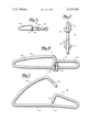
FIG. 1 is a side elvation view of the improved snap in enlarged view and with hook extremities open.
FIG. 2 is a right end elevation view of the snap of FIG. 1;
FIG. 3 is a side elevation view of the snap with the hook extremities in the closed position; and,
FIG. 4 is a side elevation view of the snap in a closed position with a swivel attached thereto, showing the application of the same.
My improved wire snap is shown generally at 10 in FIGS. 1, 2, and 3. It is comprised of a piece of wire having high tensile strength, such as steel wire, and of a given length having its ends bent as indicated at 15 and 20. The bent ends define a central body portion 16 having a slight bend 18 along the extent of the same, as will be best seen in FIG. 1. The bent ends 15 and 20 have bent hook extremities or tips indicated at 17 and 22, which hook extremities are generally symmetrical in shape being bent to basically the same radius and offset from the general extent of the bent portion through the same angular displacement, as indicated at 23, such that the hook extremities fit around the main body portion as will be best seen in FIGS. 3 and 4. The bent end 15 with its hook extremity 17 fits over the central body portion and hooks around the same generally in the location of the bend 18 to define a first loop 25 in the wire snap. Similarly, the bent end 20 with its hook extremity 22 fits around the main body portion 16 and overlies the hook extremity 17 for purposes to be hereinafter noted. When secured to the main body portion, it will define a second larger loop 30 for the wire snap. As shown in FIG. 3, the bend end 20, except for the hook tip 22, extends at an acute angle to the central body portion 16, and the bent end 15, except for the hook tip 17, extends substantially parallel to the central body portion 16 in a closed position of the wire snap forming the first and second loops. The length and width of the loop area 30 of the bent portion 20 of the wire snap is generally twice as large as the loop dimensions for the loop 25 formed by the bent wire portion 15. The hook portions 17 and 22 have the same radius of curvature which is slightly larger than the diametrical dimension of the wire such that it fits snugly around the central body portion, the hooks being directed in opposite directions so as to provide a relatively smooth surface area across the general outline of the snap. Similarly, the bent portions 15 and 20 of the wire snap in the closed and open position, except for the hook extremities 17 and 22 and the bent portions 23 thereof, generally fall in the same plane as the body portion 16 and the bend portions 23 allow for the hook extremities to overlap without displacing the bent portions 15 and 20 from this alignment in the same plane. The length of the bent portion 20 including its hook extremity is in the ratio of slightly greater than 2:1 to the length of the bent portion 15 and its hook extremity.
The smaller loop 25 in the wire snap provides a mounting for a swivel such as indicated at 40 in FIG. 4 and the same may be applied by opening the bent portion 15 and adding the swivel thereto. Thus, the swivel does not have to be permanently installed on the wire snap at the time of manufacture and may be used or omitted as desired. The overlap of the hook extremities increases significantly the strength of the wire snap in that the pulling force on the ends of the snap will tend to draw the hook extremities 17, 22 into contact with one another and the main body portion 16 significantly increasing the tensile strength of the wire snap. The larger loop of the wire snap may be utilized for attachment of the lure or leader as desired.
The improved wire snap is made from a single piece of wire without requirement of additional parts and with generally symmetrical bends in the same to provide a simplified wire snap which is relatively low in cost. When the snap is made of a high tensile steel wire, it provides a wire snap having exceptional tensile strength. It may be readily opened or unsnapped for attachment of a lure or leader to the larger loop extremity and, if desired, the smaller loop may be opened to permit the mounting of a swivel thereon.
In considering this invention it should be remembered that the present disclosure is illustrative only and the scope of the invention should be determined by the appended claims.
Claims (2)
1. A wire snap comprising: a single length of tensile steel wire with the ends bent back toward one another defining a central body portion therebetween, one end being bent back toward the central body portion and defining a first loop therewith and with the extremity of said end having a transverse hook tip adapted to fit around and secure said end to the central body portion and the other end being bent toward the central body portion defining a second loop therewith and having a transverse hook tip adapted to fit around and secure the other end to the central body portion, each of said transverse hook tips of said one and said other ends of said wire being bent toward one another and extending respectively beyond the transverse hook tip of the opposite end of said wire and fitting around the central body portion in an opposite direction with its hook tip being disposed adjacent that of the other and having the same radius of curvature, the bent end of the wire forming the first loop with the central portion being substantially parallel with the central body portion except for the hook tip and the bent end of the wire forming the second loop with the central body portion extending at an acute angle away from the central body portion along substantially a straight line to a point adjacent its hook tip, said first loop having a length dimension relative to the second loop each in the radio of 1:2 with said bent ends of said wire being positioned in the same plane as the central body portion except for the hook tips.
2. A wire snap comprising: a single length of tensile steel wire with the ends bent back toward one another and defining a central body portion therebetween, one end portion being bent back toward the central body portion and extending parallel thereto and defining a first loop therewith with the extremity of said end having a transverse hook tip adapted to fit around and secure said end to the central body portion, and the other end portion being bent back toward the central body portion and extending away therefrom at an acute angle thereto along substantially a straight line to to a point adjacent said hook tip and defining a second loop therewith and having a transverse hook tip adapted to fit around and secure the other end to the central body portion, said transverse hook tips of said ends of said wire being each bent toward one another and extending respectively beyond the transverse hook tip of the opposite end of said wire and fitting around the central body portion in an opposite direction with its hook tip being disposed adjacent that of the other, each of said bend ends extending throughout its length in the same plane as said central body portion except for said hook tips.
Priority Applications (1)
| Application Number | Priority Date | Filing Date | Title |
|---|---|---|---|
| US05/953,262 US4234998A (en) | 1978-10-20 | 1978-10-20 | Wire snap |
Applications Claiming Priority (1)
| Application Number | Priority Date | Filing Date | Title |
|---|---|---|---|
| US05/953,262 US4234998A (en) | 1978-10-20 | 1978-10-20 | Wire snap |
Related Parent Applications (1)
| Application Number | Title | Priority Date | Filing Date |
|---|---|---|---|
| US05853039 Continuation | 1977-11-21 |
Publications (1)
| Publication Number | Publication Date |
|---|---|
| US4234998A true US4234998A (en) | 1980-11-25 |
Family
ID=25493759
Family Applications (1)
| Application Number | Title | Priority Date | Filing Date |
|---|---|---|---|
| US05/953,262 Expired - Lifetime US4234998A (en) | 1978-10-20 | 1978-10-20 | Wire snap |
Country Status (1)
| Country | Link |
|---|---|
| US (1) | US4234998A (en) |
Cited By (24)
| Publication number | Priority date | Publication date | Assignee | Title |
|---|---|---|---|---|
| US4656699A (en) * | 1980-12-03 | 1987-04-14 | Maahs William F | Bait snap |
| US4696120A (en) * | 1987-02-13 | 1987-09-29 | Schroeder Donald R | Fishline snap connector |
| US4986500A (en) * | 1989-05-22 | 1991-01-22 | American Standard Inc. | Adjustable air brake hose support for railway vehicles |
| GB2309260A (en) * | 1996-01-17 | 1997-07-23 | Kenneth William Sharp | Detachable fixing |
| US5655329A (en) * | 1995-07-21 | 1997-08-12 | Yong-Set; Bernard | Clip for attaching articles to a line |
| USD393688S (en) | 1997-04-29 | 1998-04-21 | Normark Corporation | Fishing line and lure clip |
| US5781972A (en) * | 1996-06-24 | 1998-07-21 | Steed; John David | Fishing snap |
| USD430261S (en) * | 1999-03-04 | 2000-08-29 | Bernard Yong-Set | Clip for attaching lures to a fishing line |
| US6141839A (en) * | 1998-03-09 | 2000-11-07 | Yong-Set; Bernard | Clip for attaching lures to a fishing line |
| US20050241213A1 (en) * | 2004-03-29 | 2005-11-03 | Garber David P | Locking swivel apparatus |
| US20060248779A1 (en) * | 2005-04-07 | 2006-11-09 | Brian Settele | In-line fishing weight holder |
| US20110107558A1 (en) * | 2009-11-12 | 2011-05-12 | Strato, Inc. | Hose support strap for railway car brake line |
| US20110198449A1 (en) * | 2006-03-29 | 2011-08-18 | Murphy Wayne H | Air Hose Support Clip to Prevent Lateral Loading |
| USD760343S1 (en) * | 2014-11-26 | 2016-06-28 | Il Han Kim | Fishing line connector |
| US20160235047A1 (en) * | 2015-11-20 | 2016-08-18 | Ruben Mirabal | Fishing equipment with blade based attractor |
| USD812712S1 (en) * | 2017-01-17 | 2018-03-13 | Matthew Stark | Attachment clip for blade of an artificial fishing jig |
| US20180125175A1 (en) * | 2016-11-10 | 2018-05-10 | Aha Llc | Connection device for holding an object, such as a key, dog tag, and the like |
| USD839382S1 (en) * | 2017-03-28 | 2019-01-29 | Norman C. Furbush, Jr. | Organizational apparatus |
| USD844099S1 (en) | 2018-02-09 | 2019-03-26 | Todd Michael Cook | Device for connecting a lure to fishing line |
| US11596208B2 (en) * | 2017-09-08 | 2023-03-07 | Yugen Kaisha Houseki-No-Angel | Fastener for personal accessories |
| US20230122161A1 (en) * | 2021-10-15 | 2023-04-20 | RB Distribution, Inc. | Self-locking retainer pin |
| USD1034119S1 (en) * | 2021-12-19 | 2024-07-09 | Joseph Ware | Locking clip shank assembly |
| US12279604B2 (en) | 2018-02-09 | 2025-04-22 | Todd Michael Cook | Device for connecting a lure to fishing line |
| USD1073855S1 (en) | 2021-12-05 | 2025-05-06 | Todd Michael Cook | Device for connecting a lure to fishing line |
Citations (4)
| Publication number | Priority date | Publication date | Assignee | Title |
|---|---|---|---|---|
| US1196514A (en) * | 1916-01-10 | 1916-08-29 | Edward Ripley Burgess | Tag-fastener. |
| US1728560A (en) * | 1928-11-30 | 1929-09-17 | John F Goshorn | Snap for fishing tackle |
| US1998035A (en) * | 1934-11-08 | 1935-04-16 | Peter E Wiberg | Double snap-hook for fishing tackle |
| US2240693A (en) * | 1940-04-26 | 1941-05-06 | Clarence H Taylor | Paper clip |
-
1978
- 1978-10-20 US US05/953,262 patent/US4234998A/en not_active Expired - Lifetime
Patent Citations (4)
| Publication number | Priority date | Publication date | Assignee | Title |
|---|---|---|---|---|
| US1196514A (en) * | 1916-01-10 | 1916-08-29 | Edward Ripley Burgess | Tag-fastener. |
| US1728560A (en) * | 1928-11-30 | 1929-09-17 | John F Goshorn | Snap for fishing tackle |
| US1998035A (en) * | 1934-11-08 | 1935-04-16 | Peter E Wiberg | Double snap-hook for fishing tackle |
| US2240693A (en) * | 1940-04-26 | 1941-05-06 | Clarence H Taylor | Paper clip |
Cited By (32)
| Publication number | Priority date | Publication date | Assignee | Title |
|---|---|---|---|---|
| US4656699A (en) * | 1980-12-03 | 1987-04-14 | Maahs William F | Bait snap |
| US4696120A (en) * | 1987-02-13 | 1987-09-29 | Schroeder Donald R | Fishline snap connector |
| US4986500A (en) * | 1989-05-22 | 1991-01-22 | American Standard Inc. | Adjustable air brake hose support for railway vehicles |
| US5655329A (en) * | 1995-07-21 | 1997-08-12 | Yong-Set; Bernard | Clip for attaching articles to a line |
| GB2309260B (en) * | 1996-01-17 | 2000-05-31 | Kenneth William Sharp | Detachable fixing |
| GB2309260A (en) * | 1996-01-17 | 1997-07-23 | Kenneth William Sharp | Detachable fixing |
| US5729870A (en) * | 1996-01-17 | 1998-03-24 | Sharp; Kenneth | Detachable fixing |
| US5781972A (en) * | 1996-06-24 | 1998-07-21 | Steed; John David | Fishing snap |
| USD393688S (en) | 1997-04-29 | 1998-04-21 | Normark Corporation | Fishing line and lure clip |
| US6141839A (en) * | 1998-03-09 | 2000-11-07 | Yong-Set; Bernard | Clip for attaching lures to a fishing line |
| USD430261S (en) * | 1999-03-04 | 2000-08-29 | Bernard Yong-Set | Clip for attaching lures to a fishing line |
| US20050241213A1 (en) * | 2004-03-29 | 2005-11-03 | Garber David P | Locking swivel apparatus |
| US7513075B2 (en) | 2004-03-29 | 2009-04-07 | Garber David P | Locking swivel apparatus |
| US20090255170A1 (en) * | 2004-03-29 | 2009-10-15 | Garber David P | Locking swivel apparatus |
| US20060248779A1 (en) * | 2005-04-07 | 2006-11-09 | Brian Settele | In-line fishing weight holder |
| US20110198449A1 (en) * | 2006-03-29 | 2011-08-18 | Murphy Wayne H | Air Hose Support Clip to Prevent Lateral Loading |
| US8167251B2 (en) | 2006-03-29 | 2012-05-01 | Murphy Wayne H | Air hose support clip to prevent lateral loading |
| US8201779B2 (en) * | 2009-11-12 | 2012-06-19 | Strato, Inc. | Hose support strap for railway car brake line |
| US20110107558A1 (en) * | 2009-11-12 | 2011-05-12 | Strato, Inc. | Hose support strap for railway car brake line |
| USD760343S1 (en) * | 2014-11-26 | 2016-06-28 | Il Han Kim | Fishing line connector |
| US20160235047A1 (en) * | 2015-11-20 | 2016-08-18 | Ruben Mirabal | Fishing equipment with blade based attractor |
| US20180125175A1 (en) * | 2016-11-10 | 2018-05-10 | Aha Llc | Connection device for holding an object, such as a key, dog tag, and the like |
| USD812712S1 (en) * | 2017-01-17 | 2018-03-13 | Matthew Stark | Attachment clip for blade of an artificial fishing jig |
| USD839382S1 (en) * | 2017-03-28 | 2019-01-29 | Norman C. Furbush, Jr. | Organizational apparatus |
| USD873954S1 (en) * | 2017-03-28 | 2020-01-28 | Norman C. Furbush, Jr. | Organizational apparatus |
| USD900275S1 (en) | 2017-03-28 | 2020-10-27 | Norman C. Furbush, Jr. | Organizational apparatus |
| US11596208B2 (en) * | 2017-09-08 | 2023-03-07 | Yugen Kaisha Houseki-No-Angel | Fastener for personal accessories |
| USD844099S1 (en) | 2018-02-09 | 2019-03-26 | Todd Michael Cook | Device for connecting a lure to fishing line |
| US12279604B2 (en) | 2018-02-09 | 2025-04-22 | Todd Michael Cook | Device for connecting a lure to fishing line |
| US20230122161A1 (en) * | 2021-10-15 | 2023-04-20 | RB Distribution, Inc. | Self-locking retainer pin |
| USD1073855S1 (en) | 2021-12-05 | 2025-05-06 | Todd Michael Cook | Device for connecting a lure to fishing line |
| USD1034119S1 (en) * | 2021-12-19 | 2024-07-09 | Joseph Ware | Locking clip shank assembly |
Similar Documents
| Publication | Publication Date | Title |
|---|---|---|
| US4234998A (en) | Wire snap | |
| US4321891A (en) | Adjustable animal collar | |
| US3122803A (en) | Connector for fishing tackle | |
| US5781972A (en) | Fishing snap | |
| US4092796A (en) | Fishing hook | |
| US4004328A (en) | Snap hook for fishing tackle | |
| US5042191A (en) | Clip for attaching a fishing lure and the like | |
| US2138702A (en) | Line coupler | |
| KR20000022216A (en) | Fish hook and knot therefor | |
| US4100658A (en) | Fishing lure-and-line snap swivel | |
| US2778141A (en) | Fishing line guide | |
| US6141839A (en) | Clip for attaching lures to a fishing line | |
| US2759290A (en) | Fishing rig | |
| US4615135A (en) | Knotless weight boom | |
| US2234588A (en) | Fishhook spreader | |
| US5056257A (en) | Fish hook construction | |
| US1998035A (en) | Double snap-hook for fishing tackle | |
| US4569148A (en) | Hook positioner and rig | |
| KR100280687B1 (en) | Fish hook | |
| US4453334A (en) | Fishing lure | |
| US20050217167A1 (en) | Fishing hook and lure, snag releasing | |
| US2629199A (en) | Fish lure | |
| US2917860A (en) | Weedless fish hooks | |
| US2822637A (en) | Fishing lure | |
| US5555669A (en) | Surf fishing sinker |