US421908A - close - Google Patents
close Download PDFInfo
- Publication number
- US421908A US421908A US421908DA US421908A US 421908 A US421908 A US 421908A US 421908D A US421908D A US 421908DA US 421908 A US421908 A US 421908A
- Authority
- US
- United States
- Prior art keywords
- cylinder
- spike
- machine
- steam
- drivers
- Prior art date
- Legal status (The legal status is an assumption and is not a legal conclusion. Google has not performed a legal analysis and makes no representation as to the accuracy of the status listed.)
- Expired - Lifetime
Links
- 210000001847 Jaw Anatomy 0.000 description 8
- 238000010276 construction Methods 0.000 description 8
- JVTAAEKCZFNVCJ-UHFFFAOYSA-N lactic acid Chemical compound CC(O)C(O)=O JVTAAEKCZFNVCJ-UHFFFAOYSA-N 0.000 description 4
- 230000000284 resting Effects 0.000 description 4
- 239000005060 rubber Substances 0.000 description 4
- 201000005804 Eastern equine encephalitis Diseases 0.000 description 2
- 229920003171 Poly (ethylene oxide) Polymers 0.000 description 2
- 239000010985 leather Substances 0.000 description 2
- 239000000463 material Substances 0.000 description 2
- 230000000979 retarding Effects 0.000 description 2
- 239000002023 wood Substances 0.000 description 2
Images


Classifications
-
- E—FIXED CONSTRUCTIONS
- E01—CONSTRUCTION OF ROADS, RAILWAYS, OR BRIDGES
- E01B—PERMANENT WAY; PERMANENT-WAY TOOLS; MACHINES FOR MAKING RAILWAYS OF ALL KINDS
- E01B29/00—Laying, rebuilding, or taking-up tracks; Tools or machines therefor
- E01B29/24—Fixing or removing detachable fastening means or accessories thereof; Pre-assembling track components by detachable fastening means
- E01B29/26—Fixing or removing detachable fastening means or accessories thereof; Pre-assembling track components by detachable fastening means the fastening means being spikes
Definitions
- the object of my invention is to construct a railway spiking-machine with a steam-engine attached to propel the machine on the railway-track, and also to operate the machine.
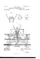
- I attain this object by the mechanism illustrated in the accompanying drawings, in which- Figure 1 represents a vertical transverse section of my improved spike-driving machine on line 00 w of Fig. 5, with the driver, cams, and atmospheric cylinder removed from one side.
- Fig. 2 is a top view of the receptacle for holding the spikes.
- Fig. 3 is a top view of the atmospheric cylinders and a part of the counter-shaft with the cams attached thereon.
- Fig. 1 is a side elevation, partly in section, of the entire machine.
- Fig. 6 is an enlarged detached view of the spike-catching cylinder, representing the beveled slots for catching the spikes; and
- Fig. 7 is a top view of the same cylinder, showing the beveling of the slots from outside to inside of the cylinder.
- Fig. 8 is a top view of the steam-cylinder, cover detached, showing the jaws at each corner for receiving and connecting both the lifter-hook rods, the brake-rods, and the belttightener rods thereon.
- a top view of the spike-catching cylinder is also represented on this view with piston-rod in the center.
- Figs. 9 to 14. are views in detail.
- the three floors 0r bearers H H H and vertical braces P P P, with the hangers P P constitute the frame-work of the machine.
- the jaws P P Secured under the lower floor are the jaws P P, on which the frame is mounted, with the jaws resting 011 the journal of the axle-tree.
- the counter-shaft N receives its motion from shaft N, which in the drawings is represented by the double' crank N and eccentric attached to main shaft.
- the pistons inside of the atmospheric cylinders B B 13 are secured to the drivers and compress the air as the drivers are being forced up by the cams, and as soon as the cams release the pivots the drivers, by the aid of the vacuum and compressed airformed in the cylinder, combined with the expansion of the springs, impart a swift and powerful stroke to the drivers and give the desired blow to drive the spike.
- the atmospheric cylinders' may be converted into steam-cylinders, and the drivers operated by steam in the wellknown manner of stean1-hammers, or they may receive power from the air-pump E, operated by the main engine.
- the drivers in being raised may form a vacuum below the piston or may be raised up against compressed air, coil, or elliptic, or any other kind of spring, by hand or any known motive power.
- the steam-cylinder B, Fig. 1 is operated by the steam passing from the boiler II, Fig. 1, through the steam-pipe L and the hollow piston-rod a.
- the piston-rod I supply with the opening (3, which permits the steam to enter into the interior of the cylinder, just above thestationary piston, and the piston and piston-rod may be cast or forged in one and the same piece.
- the lower end of the piston-rod I secure to the frame or floor with bolts.
- the spike-Catching cylinder or ring 13, I attach to the upper end of the steam-cyh inder B either by being cast in one and the same piece, or they maybe made separate and bolted together.
- Top cylinder B on its upward course passes through the spike-receptacle B Fig. 1, and carries with it several of the spikes g g by engaging them as they are found caught in the beveled slots U U, Fig. 6.
- the slots are fork-shaped or beveled at their upper ends to correspond with the beveled under side of the spike-heads. I' also bevel the sides of the slots from the outside to the inside of the cylinder, as may be seen in Fig. 7. In this manner a recess is formed in the cylinder for the purpose of holding the spike perpendicular, the slots not being large enough to permit the spikes entering into the 'interior of the cylinder.
- the upper end of the cylinder I provide with a conical-shaped cover, as represented in Fig. 1, which is designed to prevent the spikes entering into the interior of the cylinder.
- EEE, Fig. 1 represent the spike-conveyors, N o. 2 being twisted so as to reverse the spikeheads before they arrive in the holders at the lower ends of the conveyers, and the bottom or inner sides of the upper .ends of the conveyers form an elastic spring A A, Figs. 1 and 12, which penetrate or spring into beveled slots under the pointof the spike.
- the spike passes by as the cylinder makes its upward movement, and as it is moving do Pvnward the spike is caught by the spring and by it deposited into the conveyer, as represented in Fig.
- the spring may be secured to the stationary piston-rod, as also re resented in Fi 12 at a a and as the cvlif necessa ry-which are operated from the cylinder B by the connections P and the slotted bell-cranks X, which are pivoted in the hangers D and secured to the conveyor, as may be seen on Fig. 1.
- N0. 1 Fig. 4, represents a side and sectional view of the spike-holders, with a spike inclosed and the spike-driver n restingthereon.
- No. 2 represents the front sectional view of the same, with the spike-driver n omitted.
- the holder could be made undivided and supplied with rubber, elliptic, spiral, or any kind of elastic springs, either by placing them inside of it, as represented in Nos. at and 5, X X X X or securing them to the outside of the holders, as seen in No. 6, X X.
- Fig. 1 is a vertical sectional view
- Fi g. 2 is a top view, of the same detached, representing an opening to admit the spike-catching cylinder B to enter, and the spikes g g resting thereon. It represents, also, the spike-conveyers E E E.
- the cylinder B maybe operated in the usual manner, and by any of the well known valves and valve-gear, and, as herein represented in Fig. 1, I have attached a cylinder-valve C to the steam-pipe L, and the valve 0 is connected to the cylinder B by the rod D and the valve lever C, and, as seen in the detached view,
- the wheels K K, Fig. 1, as represented, are double-flanged or V-shaped, so as to act as a track-gage, and if found necessary I contemplate attaching other additional track-gages to and in front of the spiking-machine.
- I propel the machine by belts Q Q, which are operated on by the belt-tighteners S S, Fig. 5, connected by the rods a a to the steam-cylinder B, and as the cylinder is descending the tightener lowers and presses against and imparts the necessary power to the belts to turn the wheels K K, and thus move the machine to the next tie.
- the cylinder is descending both the lifterhooks and brakes are simultaneously released, as previously stated.
- the machine may be propelled on the rails, as represented in Figs. 1 and 5, by the loose belts Q Q, provided with the belt-tightener S S, Fig. 5, or other suitable motive power.
- the wheels K K with the entire machine, could be manipulated in the same manner that railroad hand-cars are by placinga crank with handles to both ends of the main shaft N, or, instead of the crank and handles, the present style of gearing and levers could be adopted and attached to shaft N, as at present in common use on railroad-section hand-cars.
- it would dispense with the cylinder E Fig. 5, and by placing an additional eccentric or double crank on the main shaft N, Fig. 5, with its connecting-rod leading from the eccentric to a vibrating joint connecting with the cylinder B, the steam-boiler I-I could also be dispensed with; but I prefer the present mode I of constructing and operating a machine, as
- the drivers 01 n provided with regulators or stops a a and the additional stops a a substan tially as shown, for the purpose specified.
- the lifter-hooks O O in combination with the railway tie and rail and means to drive the spikes, substantially as shown, for the purpose specified.
Description
(No Model.) 3 Sheets-Sheet 1.
J. W. CLOSE.
MACHINE FOR RAILWAY CONSTRUCTION.
Patented Feb. 25, 1890.
NJETENS, PhoQo-Lilhcgmphor. Washingmn u. c,
3 Sheets Sh eet 2.
(No Model.) J. W. CLOSE. MACHINE POE RAILWAY CONSTRUCTION. N0. 421.908. Patented Feb. 25. 1890 wgmssas: INVENTOR flaw m' a... @zmwM 7Q ATTORNEY N. PETERS. PlfaloLithogrnpbar, Washington. D. Q
(No Model.) 3 Sheets-Sheet a. J. W. CLOSE. MACHINE FOR RAILWAY UONSTRUGTION. No. 421,908; Patented Feb. 25,1890.
IIIIIIIIIJ Wviwwesses; Iwve HID?- mxam WWW/M )2!" my N. PETER5. Phololilhagrnphar. Washingwn, u c.
UNITED STATES ATENT OFFICE.
JOHN CLOSE, OF BUFFALO, NEIV YORK, ASSIGNOR OF ONE-HALF TO JOHN C. GRAVES, OF SAME PLACE.
MACHINE FOR RAILWAY CONSTRUCTION.
SPECIFICATION forming part of Letters Patent No. 421,908, dated February 25, 1890.
Application filed July 18, 1881. Serial No. 88,011- (No model.)
To all whom it may concern.-
Be it known that 1, JOHN WVHITNEY CLOSE, of the city of Buffalo, in the county of Erie and State of New York, have invented certain new and useful Improvements in Machinery for Railway Construction; and I hereby declare that the followingis a full, clear, and eX- act description of the invention, which will enable others skilled in the art to which it appertains to make and use the same, reference being had to the accompanying drawings, and the letters of reference marked thereon, which form a part of this specification.
' The object of my invention is to construct a railway spiking-machine with a steam-engine attached to propel the machine on the railway-track, and also to operate the machine. I attain this object by the mechanism illustrated in the accompanying drawings, in which- Figure 1 represents a vertical transverse section of my improved spike-driving machine on line 00 w of Fig. 5, with the driver, cams, and atmospheric cylinder removed from one side. Fig. 2 is a top view of the receptacle for holding the spikes. Fig. 3 is a top view of the atmospheric cylinders and a part of the counter-shaft with the cams attached thereon. Fig. 4, Nos. 1, 2, and 3, are detached sectional views of the spike holders and guides located at the lower ends of the spike-conveyers. Fig. 5 is a side elevation, partly in section, of the entire machine. Fig. 6 is an enlarged detached view of the spike-catching cylinder, representing the beveled slots for catching the spikes; and Fig. 7 is a top view of the same cylinder, showing the beveling of the slots from outside to inside of the cylinder. Fig. 8 is a top view of the steam-cylinder, cover detached, showing the jaws at each corner for receiving and connecting both the lifter-hook rods, the brake-rods, and the belttightener rods thereon. A top view of the spike-catching cylinder is also represented on this view with piston-rod in the center. Figs. 9 to 14. are views in detail.
Similar-1e tters refer to similar parts thro ughout the several views.
The three floors 0r bearers H H H and vertical braces P P P, with the hangers P P constitute the frame-work of the machine. Secured under the lower floor are the jaws P P, on which the frame is mounted, with the jaws resting 011 the journal of the axle-tree. In the hangers P turns the shaft N, Fig. 5, which is driven by the crank N and operated by the cylinder E The counter-shaft N receives its motion from shaft N, which in the drawings is represented by the double' crank N and eccentric attached to main shaft. To the countershaft I secure the cams a a a, Figs. 1 and 3, which operate the drivers a n n by revolw ing and coming in contact with the pivots 02 :0, Fig. 1, secured to the drivers, and thus the drivers are forced up by the cams; and, to reenforce or add greater rapidity to the descending drivers, I place coil-springs O 0 around the drivers, which are pressed up and against the floor by the cams.
The pistons inside of the atmospheric cylinders B B 13 are secured to the drivers and compress the air as the drivers are being forced up by the cams, and as soon as the cams release the pivots the drivers, by the aid of the vacuum and compressed airformed in the cylinder, combined with the expansion of the springs, impart a swift and powerful stroke to the drivers and give the desired blow to drive the spike.
To prevent the drivers breaking the thin flange of the rail, as the head of the spike is being driven down onto it, I place regulators or stops a (L2, Fig. 1, on the drivers, with the additional steps a a at the lower end of the drivers, and that part of the regulators which comes in contact with the rail I cushion wlth rubber, wood, leather, or any other elastic material that will prevent marring or breaking the rail. If preferred,the atmospheric cylinders'may be converted into steam-cylinders, and the drivers operated by steam in the wellknown manner of stean1-hammers, or they may receive power from the air-pump E, operated by the main engine. The drivers in being raised may form a vacuum below the piston or may be raised up against compressed air, coil, or elliptic, or any other kind of spring, by hand or any known motive power.
The steam-cylinder B, Fig. 1, is operated by the steam passing from the boiler II, Fig. 1, through the steam-pipe L and the hollow piston-rod a. The piston-rod I supply with the opening (3, which permits the steam to enter into the interior of the cylinder, just above thestationary piston, and the piston and piston-rod may be cast or forged in one and the same piece. The lower end of the piston-rod I secure to the frame or floor with bolts. The spike-Catching cylinder or ring 13, I attach to the upper end of the steam-cyh inder B either by being cast in one and the same piece, or they maybe made separate and bolted together.
The operation of this part of my invention is as follows: Top cylinder B on its upward course passes through the spike-receptacle B Fig. 1, and carries with it several of the spikes g g by engaging them as they are found caught in the beveled slots U U, Fig. 6. The slots are fork-shaped or beveled at their upper ends to correspond with the beveled under side of the spike-heads. I' also bevel the sides of the slots from the outside to the inside of the cylinder, as may be seen in Fig. 7. In this manner a recess is formed in the cylinder for the purpose of holding the spike perpendicular, the slots not being large enough to permit the spikes entering into the 'interior of the cylinder. The upper end of the cylinder I provide with a conical-shaped cover, as represented in Fig. 1, which is designed to prevent the spikes entering into the interior of the cylinder.
EEE, Fig. 1, represent the spike-conveyors, N o. 2 being twisted so as to reverse the spikeheads before they arrive in the holders at the lower ends of the conveyers, and the bottom or inner sides of the upper .ends of the conveyers form an elastic spring A A, Figs. 1 and 12, which penetrate or spring into beveled slots under the pointof the spike. The spike passes by as the cylinder makes its upward movement, and as it is moving do Pvnward the spike is caught by the spring and by it deposited into the conveyer, as represented in Fig. 12, a a; or, if preferred, the spring may be secured to the stationary piston-rod, as also re resented in Fi 12 at a a and as the cvlif necessa ry-which are operated from the cylinder B by the connections P and the slotted bell-cranks X, which are pivoted in the hangers D and secured to the conveyor, as may be seen on Fig. 1.
N0. 1, Fig. 4, represents a side and sectional view of the spike-holders, with a spike inclosed and the spike-driver n restingthereon. No. 2 represents the front sectional view of the same, with the spike-driver n omitted.
In order to hold the spike upright in the holder, as seen in No. 2, I separate or make the holder and a part of the conveyer in halves, as more clearly seen in No. 3, R R and NV. By this means I gain sufficient elasticity to clasp and hold the body of the spike perpendicularly while it is being driven.
If desired, the holder could be made undivided and supplied with rubber, elliptic, spiral, or any kind of elastic springs, either by placing them inside of it, as represented in Nos. at and 5, X X X X or securing them to the outside of the holders, as seen in No. 6, X X.
To the upper fioor is secured the spike-receptacle B Fig. 1 is a vertical sectional view, and Fi g. 2 is a top view, of the same detached, representing an opening to admit the spike-catching cylinder B to enter, and the spikes g g resting thereon. It represents, also, the spike-conveyers E E E.
Instead of the usual manner of using a le ver to hold and press the tie up and against the rail while the spikes are being driven, I employ the lifter-hooks C C, Fig. 5. The upper ends of the lifter-hook rods 0 C, which are jointed in the'upper ends of thelift-hooks, I attach. to the steam-cylinder cover in the jaws Z Z, Figs. 1 and 8, and while the spikes are being driven the hooks grasp the tie, represented in Fig. 5. This is accomplished by the steam-cylinder as it is traveling on and guided by the piston-rod a, Fig. 1. WV'hen the hooks are pressing the tie up against the rail, as represented, the steam-cylinder is at its height. At the lower crossing of the hooks they are pivoted into the braces D D, Figs. 1 and 5, and as the cylinder is descending the hooks are forced apart and raised sufficiently high to pass over the next tie to be spiked.
In practice it is usual to place the ties at a uniform distance apart, about eighteen inches from each other. Therefore it is necessary that the spiking-machine should be provided with an attachment or feeding apparatus that will regulate or stop at the required uniform distances and place the drivers over the re quired position to drive the spikes. As one plan of many that could. be used for that purpose, I have placed the brakes to the wheels K K with the brake-rods T T, as shown in Fig. 5. Said brake-rods I attach to and operate by the cylinder in the same manner as the tielifter rods are, and as above described, so that when the cylinder is at its height the brakerods are fully set to the wheels, as represented in Fig. 5.
The cylinder B maybe operated in the usual manner, and by any of the well known valves and valve-gear, and, as herein represented in Fig. 1, I have attached a cylinder-valve C to the steam-pipe L, and the valve 0 is connected to the cylinder B by the rod D and the valve lever C, and, as seen in the detached view,
IOO
Fig. 14, as the cylinder B is descending the valve 0' advancesover and closes the exhaustport R and at the same time the under side of the valve has retired from over and opened the lower port R of the steam-pipe L, thereby permitting the steam to enter the cylinder again, and so on continue the operation of the cylinder and machine. That portion of the cylinder underneath the stationary piston I freely expose to the outer air, so as to prevent vacuum or pressure retarding the motion of the cylinders.
The wheels K K, Fig. 1, as represented, are double-flanged or V-shaped, so as to act as a track-gage, and if found necessary I contemplate attaching other additional track-gages to and in front of the spiking-machine.
As represented in Fig. 5, I propel the machine by belts Q Q, which are operated on by the belt-tighteners S S, Fig. 5, connected by the rods a a to the steam-cylinder B, and as the cylinder is descending the tightener lowers and presses against and imparts the necessary power to the belts to turn the wheels K K, and thus move the machine to the next tie. As the cylinder is descending both the lifterhooks and brakes are simultaneously released, as previously stated.
The machine may be propelled on the rails, as represented in Figs. 1 and 5, by the loose belts Q Q, provided with the belt-tightener S S, Fig. 5, or other suitable motive power.
The wheels K K, with the entire machine, could be manipulated in the same manner that railroad hand-cars are by placinga crank with handles to both ends of the main shaft N, or, instead of the crank and handles, the present style of gearing and levers could be adopted and attached to shaft N, as at present in common use on railroad-section hand-cars. Should the above plan of manipulation be preferred, it would dispense with the cylinder E Fig. 5, and by placing an additional eccentric or double crank on the main shaft N, Fig. 5, with its connecting-rod leading from the eccentric to a vibrating joint connecting with the cylinder B, the steam-boiler I-I could also be dispensed with; but I prefer the present mode I of constructing and operating a machine, as
herein specified and represented in the accompanying drawings.
The above plan of manipulating the machine just referred to and described forms no part of my present invention.
I am aware that prior to my invention machines have been made with atmospheric cylinders supplied with air pu mps and coil and elliptic springs, operating in conjunction with rotating cams. I therefore do not claim such a combination, broadly; but
WVhat I do claim as my invention, and desire to secure by Letters Patent, is as follows:
1. The combination, in a spike-driving ma chine, of a stationary piston, secured to a sta tionary hollow pistondod a, with its steam or atmospheric cylinder B and spike-catching cylinder B traveling thereon and guided thereby, having the devices for feeding the spikes to the rails, belt-tightener rodsct a lifter-hook rods 0 O, and the brake-rods T T, all connected to and operated in conjunction with steam-cylinder B, substantially as and for the purpose specified and shown.
2. The combination of the slotted spikecatching cylinder B with the spike-receptacle B and the conveyers E E E, attached thereto and provided with spike-detaching springs A A, with the spike-holders E E, all adapted to operate substantially as and for the purpose described.
3. In a machine for driving spikes, the drivers 01 n, provided with regulators or stops a a and the additional stops a a substan tially as shown, for the purpose specified.
4. The combination and arrangement, with the spike-drivers n n, of the cushioned stops a a and a a substantially as described.
5. The lifter-hooks O O, in combination with the railway tie and rail and means to drive the spikes, substantially as shown, for the purpose specified.
6. I11 a railway spiking-machine, the combination, with the catching cylinder or ring and con veyers and hammers, of means for advancing the apparatus and stopping the same the required and uniform distance, as and for the purpose set forth.
7. In a railway spikingnnachine, the combination of the truck provided with the gaging-wheels, of the lifters and mechanismto advance the machine the required and uniform distance, substantially as set forth.
8. In a spike-driving machine, the combination, with the catching cylinder or ring, the
conveyers, and the hammers, of the doubleflanged wheels R R, adapted to gage the track as the machine advances, substantially as and for the purpose set forth.
9. In a railway spiking-machine, the combination. of a hopper, a spike-catching cylinder, slotted as described, spike-convcyers, and suitable drivers, as set forth.
10. The combination of the steam-cylinder, the brakes, andthe described connections thereof with said cylinder, for the purposes set forth.
11. The combination of the steam-cylinder, the brakes, the belt-tightener, and their described connections to the cylinder, as set forth.
12. In a track-spiking machine, the combination, with the driving hammer or hammers n, of the lifters for lifting and holding the tie to place, together with the operating and sup porting parts, substantially as set forth.
J. w. CLOSE.
Publications (1)
| Publication Number | Publication Date |
|---|---|
| US421908A true US421908A (en) | 1890-02-25 |
Family
ID=2490826
Family Applications (1)
| Application Number | Title | Priority Date | Filing Date |
|---|---|---|---|
| US421908D Expired - Lifetime US421908A (en) | close |
Country Status (1)
| Country | Link |
|---|---|
| US (1) | US421908A (en) |
Cited By (4)
| Publication number | Priority date | Publication date | Assignee | Title |
|---|---|---|---|---|
| US2562287A (en) * | 1946-08-07 | 1951-07-31 | Carmen D Webster | Implement for laying model railway tracks |
| US2799230A (en) * | 1954-07-06 | 1957-07-16 | Nordberg Manufacturing Co | Rail spike driving machine |
| US3163122A (en) * | 1961-03-06 | 1964-12-29 | Fairmont Railway Motors Inc | Apparatus for setting and driving railroad spikes |
| US4637314A (en) * | 1985-06-20 | 1987-01-20 | Gower David I | Railroad spike resinstallation apparatus |
-
0
- US US421908D patent/US421908A/en not_active Expired - Lifetime
Cited By (4)
| Publication number | Priority date | Publication date | Assignee | Title |
|---|---|---|---|---|
| US2562287A (en) * | 1946-08-07 | 1951-07-31 | Carmen D Webster | Implement for laying model railway tracks |
| US2799230A (en) * | 1954-07-06 | 1957-07-16 | Nordberg Manufacturing Co | Rail spike driving machine |
| US3163122A (en) * | 1961-03-06 | 1964-12-29 | Fairmont Railway Motors Inc | Apparatus for setting and driving railroad spikes |
| US4637314A (en) * | 1985-06-20 | 1987-01-20 | Gower David I | Railroad spike resinstallation apparatus |
Similar Documents
| Publication | Publication Date | Title |
|---|---|---|
| US421908A (en) | close | |
| US2926617A (en) | Ballast tamping apparatus | |
| US712167A (en) | Tie-plate machine. | |
| US785252A (en) | Apparatus for raising superstructures and ballasting railway road-beds. | |
| US408765A (en) | Box-nailing machine | |
| US1351106A (en) | Tamping-machine | |
| US2697887A (en) | Auger type ballast excavator | |
| US953668A (en) | Tool-car. | |
| US262746A (en) | Tamping-car | |
| US395095A (en) | Machine for making multitubular pipe | |
| US833038A (en) | Track-laying machine. | |
| US435973A (en) | Machine for channeling rock | |
| US669777A (en) | Railway-track making and laying machine. | |
| US1110937A (en) | Hackling-machine. | |
| US630918A (en) | Press. | |
| US2000458A (en) | Adzing and boring machine | |
| US424708A (en) | Sewer-sheathing driver | |
| US541103A (en) | Gluing-machine | |
| US550347A (en) | Train-starter | |
| US703419A (en) | Means for driving shuttles of looms. | |
| US409980A (en) | Double-acting bellows | |
| US404447A (en) | Car-dumping apparatus | |
| US553967A (en) | System of supplying water to locomotives | |
| US1024669A (en) | Pneumatic percussive apparatus. | |
| US731806A (en) | Railroad transfer-table. |