US4218099A - Wheel cover having snap-on retention means - Google Patents
Wheel cover having snap-on retention means Download PDFInfo
- Publication number
- US4218099A US4218099A US05/958,982 US95898278A US4218099A US 4218099 A US4218099 A US 4218099A US 95898278 A US95898278 A US 95898278A US 4218099 A US4218099 A US 4218099A
- Authority
- US
- United States
- Prior art keywords
- axially
- tab
- retention
- extending
- wheel
- Prior art date
- Legal status (The legal status is an assumption and is not a legal conclusion. Google has not performed a legal analysis and makes no representation as to the accuracy of the status listed.)
- Expired - Lifetime
Links
Images
Classifications
-
- B—PERFORMING OPERATIONS; TRANSPORTING
- B60—VEHICLES IN GENERAL
- B60B—VEHICLE WHEELS; CASTORS; AXLES FOR WHEELS OR CASTORS; INCREASING WHEEL ADHESION
- B60B7/00—Wheel cover discs, rings, or the like, for ornamenting, protecting, venting, or obscuring, wholly or in part, the wheel body, rim, hub, or tyre sidewall, e.g. wheel cover discs, wheel cover discs with cooling fins
- B60B7/06—Fastening arrangements therefor
- B60B7/10—Fastening arrangements therefor comprising a plurality of spaced spring clips individually mounted on the cover, e.g. riveted, welded or readily releasable
-
- Y—GENERAL TAGGING OF NEW TECHNOLOGICAL DEVELOPMENTS; GENERAL TAGGING OF CROSS-SECTIONAL TECHNOLOGIES SPANNING OVER SEVERAL SECTIONS OF THE IPC; TECHNICAL SUBJECTS COVERED BY FORMER USPC CROSS-REFERENCE ART COLLECTIONS [XRACs] AND DIGESTS
- Y10—TECHNICAL SUBJECTS COVERED BY FORMER USPC
- Y10T—TECHNICAL SUBJECTS COVERED BY FORMER US CLASSIFICATION
- Y10T24/00—Buckles, buttons, clasps, etc.
- Y10T24/30—Trim molding fastener
- Y10T24/304—Resilient metal type
- Y10T24/306—Strip formed
-
- Y—GENERAL TAGGING OF NEW TECHNOLOGICAL DEVELOPMENTS; GENERAL TAGGING OF CROSS-SECTIONAL TECHNOLOGIES SPANNING OVER SEVERAL SECTIONS OF THE IPC; TECHNICAL SUBJECTS COVERED BY FORMER USPC CROSS-REFERENCE ART COLLECTIONS [XRACs] AND DIGESTS
- Y10—TECHNICAL SUBJECTS COVERED BY FORMER USPC
- Y10T—TECHNICAL SUBJECTS COVERED BY FORMER US CLASSIFICATION
- Y10T24/00—Buckles, buttons, clasps, etc.
- Y10T24/30—Trim molding fastener
- Y10T24/304—Resilient metal type
- Y10T24/307—Sheet metal formed
Definitions
- This invention relates to wheel cover members motor vehicles and, more particularly, to improved retention devices for maintaining wheel cover members in proper position on a wheel rim, the retention devices being permanently secured to the wheel cover retaining flange in snap-on engagement therewith.
- Wheel cover members including wheel trim members, are relatively light weight devices having relatively flexible outer margins including means for resiliently engaging the wheel rim to maintain the wheel cover in position on the wheel.
- the retention means are comprised of sheet metal projections formed integrally with the outer marginal flange, or are comprised of independent elements which are individually fastened to the flexible periphery of the retention ring such as by rivetting. It has been found that the individual, independent elements are essential for very heavy ornamented wheel covers. That is, the material of the retaining flange itself is insufficient to retain the wheel cover on the wheel rim due to the vertical shock loads on the wheel cover which often cause excessive deflection of the retention ring and therefore release of the wheel cover. While these individual retention elements have worked quite well, they are difficult and somewhat expensive to manufacture, particularly in view of the requirement for additional fastening means to secure the retention element to the wheel cover.
- a snap-on retention clip which in one form of the invention is provided of a one-piece construction.
- the retention means clip cooperates with slots which are provided in the retention ring to secure the retention means clip onto the wheel cover without necessitating additional fastening devices.
- a wheel cover for a vehicle wheel having an annular generally radially facing and axially extending wheel flange includes a retention ring having a generally axially extending retaining flange with an intermediate stepped portion extending generally outwardly, and a plurality of circumferentially spaced retention clips are provided in snap-on engagement with the retention ring.
- Each clip includes an axially and circumferentially extending base portion engaging the radially outward side of the retaining flange and having at least one tab at the axially outward end of the base which projects through a slot in the stepped portion of the retaining ring and axially outwardly from the radially inward side of the retaining ring.
- a reverse-bent portion is provided at the axially inner end of the base portion which encircles the free end of the retention ring and in engagement therewith.
- At least one generally radially outwardly extending retention tooth is provided on the base portion which terminates in a biting edge portion for engaging the wheel flange.
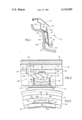
- FIG. 1 is a partial cross-sectional view of a wheel cover in conjunction with a wheel rim and illustrating a cross-sectional view of the retention means clip in accordance with the present invention
- FIG. 2 is a partial plan view of the retention means clip of FIG. 4 shown in conjunction with a partial fragmentary view of the retaining ring of the wheel cover;
- FIG. 3 is an end view of the retention means clip in accordance with the principles of the present invention.
- FIG. 1 there is shown generally at 10 a wheel cover including a retention ring 12 and an ornamental cover member 14 which is clinched, fastened or otherwise attached to the axially outer end of retention ring 12.
- Wheel cover 10 is retained on wheel rim 16 by means of snap-on retention clip 18 in accordance with the teachings of the present invention.
- Retention ring 12 includes a stepped portion 12a which separates generally axially extending portions of the retention ring 12b and 12c and which extends generally radially outwardly.
- the terms “radially outward” and “radially inward” will be employed to indicate left and right directions, respectively, as viewed in FIG. 1, and the terms “axially outward” and “axially inward” will refer to up and down directions in the same figure.
- the axis used as a reference line being that of wheel 16 which is also coincident with the axis of the wheel cover 10.
- the same terms, or the equivalence thereof, will be employed in the claims and the latter are to be interpreted in view of the above definitions.
- retention means clip 18 which is preferably formed from a flat strip or sheet of hard material such as carbon or spring steel, includes a base portion 20.
- clip 18 includes a pair of tabs 22 and 24 which extend axially outwardly at the axially outer end of base portion 20, as best illustrated in FIG. 2.
- Base portion 20 further includes a central or middle tab 26 which is formed so that it extends generally radially and axially outwardly for engagement with the axially inner side of stepped portion 12a. It can be seen that the two end tabs are respectively received within and extend axially outwardly through a pair of pierced slots 28 and 30 which are provided near the radially inner end of stepped portion 12a.
- Each end tab includes a secondary tab designated 22a and 24a in FIGS. 1 and 2.
- the secondary tabs are struck from the respective end tabs along a U-shaped line 30 at the ends of which apertures 32 are formed to relieve the stress and reduce the likelihood of tearing of the metallic material of retention means clip 18.
- Secondary tabs 22a and 24a are resilient and extend generally radially outwardly and axially inwardly for engagement with the axially outer side of stepped portion 12a after tabs 22 and 24 are inserted in the previously provided slots of retaining flange 12.
- the axially inner end of base portion 20 is provided with a reverse-bent hairpin snap-on portion 34 which encircles the free end 12d of retaining flange 12.
- a circumferentially extending retention tooth 36 is struck or lanced out of the base portion 20 and terminates in radially outwardly extending biting edge portions 36a and 36b which are engageable with the wheel flange 16.
- the end portions of retention tooth 36 are similarly provided with apertures 32 to relieve the stress and reduce the likelihood of tearing of the metal.
- a pair of axially extending anti-rotation teeth 38 and 40 are also struck or lanced out of the base portion at opposite ends of retention tooth 36.
- the remaining central portion of the base provides a tab 20a which is adjacent to and connected with center tab 26 for reacting therewith to tension base 20 against retaining flange 12.
- hairpin portion 34 is provided with a radially extending slot 34a which facilitates forming clip 18 in an arcuate manner so as to more closely conform to the circular shape of retaining flange 12. It should now be appreciated that clip 18 is readily installed onto retaining flange 12 of wheel cover 10 simply by inserting the projecting end tabs into the corresponding pair of slots 28 provided in stepped portion 12a of retaining flange 12.
Abstract
Description
Claims (10)
Priority Applications (2)
| Application Number | Priority Date | Filing Date | Title |
|---|---|---|---|
| US05/958,982 US4218099A (en) | 1978-11-09 | 1978-11-09 | Wheel cover having snap-on retention means |
| CA339,379A CA1124280A (en) | 1978-11-09 | 1979-11-07 | Wheel cover having snap-on retention means |
Applications Claiming Priority (1)
| Application Number | Priority Date | Filing Date | Title |
|---|---|---|---|
| US05/958,982 US4218099A (en) | 1978-11-09 | 1978-11-09 | Wheel cover having snap-on retention means |
Publications (1)
| Publication Number | Publication Date |
|---|---|
| US4218099A true US4218099A (en) | 1980-08-19 |
Family
ID=25501526
Family Applications (1)
| Application Number | Title | Priority Date | Filing Date |
|---|---|---|---|
| US05/958,982 Expired - Lifetime US4218099A (en) | 1978-11-09 | 1978-11-09 | Wheel cover having snap-on retention means |
Country Status (2)
| Country | Link |
|---|---|
| US (1) | US4218099A (en) |
| CA (1) | CA1124280A (en) |
Cited By (7)
| Publication number | Priority date | Publication date | Assignee | Title |
|---|---|---|---|---|
| US4408804A (en) * | 1979-11-13 | 1983-10-11 | Rockwell International Corporation | Composite wheel cover |
| DE3319229A1 (en) * | 1983-05-27 | 1984-11-29 | IMN Intermarknet AG, Zug | Device for retaining wheel caps on rims |
| US4736988A (en) * | 1982-02-08 | 1988-04-12 | Itt Corporation | Spring clip retention means |
| US4818033A (en) * | 1987-07-28 | 1989-04-04 | Arvidsson Krister E G | Device for preventing a wheel cap from loosening from a rim |
| US4826252A (en) * | 1988-05-06 | 1989-05-02 | Textron Inc. | Snap-in clip for wheel trim |
| US5598611A (en) * | 1994-10-07 | 1997-02-04 | Nifco Inc. | Clip and clip structure |
| US20090293392A1 (en) * | 2008-05-22 | 2009-12-03 | Tim Dykstra | Moulding Assembly |
Citations (3)
| Publication number | Priority date | Publication date | Assignee | Title |
|---|---|---|---|---|
| US2761188A (en) * | 1952-11-21 | 1956-09-04 | United Carr Fastener Corp | Fastening device |
| CA530686A (en) * | 1956-09-25 | A. Lyon George | Wheel structure | |
| US3973801A (en) * | 1975-02-13 | 1976-08-10 | Norris Industries, Inc. | Wheel trim retention means |
-
1978
- 1978-11-09 US US05/958,982 patent/US4218099A/en not_active Expired - Lifetime
-
1979
- 1979-11-07 CA CA339,379A patent/CA1124280A/en not_active Expired
Patent Citations (3)
| Publication number | Priority date | Publication date | Assignee | Title |
|---|---|---|---|---|
| CA530686A (en) * | 1956-09-25 | A. Lyon George | Wheel structure | |
| US2761188A (en) * | 1952-11-21 | 1956-09-04 | United Carr Fastener Corp | Fastening device |
| US3973801A (en) * | 1975-02-13 | 1976-08-10 | Norris Industries, Inc. | Wheel trim retention means |
Cited By (7)
| Publication number | Priority date | Publication date | Assignee | Title |
|---|---|---|---|---|
| US4408804A (en) * | 1979-11-13 | 1983-10-11 | Rockwell International Corporation | Composite wheel cover |
| US4736988A (en) * | 1982-02-08 | 1988-04-12 | Itt Corporation | Spring clip retention means |
| DE3319229A1 (en) * | 1983-05-27 | 1984-11-29 | IMN Intermarknet AG, Zug | Device for retaining wheel caps on rims |
| US4818033A (en) * | 1987-07-28 | 1989-04-04 | Arvidsson Krister E G | Device for preventing a wheel cap from loosening from a rim |
| US4826252A (en) * | 1988-05-06 | 1989-05-02 | Textron Inc. | Snap-in clip for wheel trim |
| US5598611A (en) * | 1994-10-07 | 1997-02-04 | Nifco Inc. | Clip and clip structure |
| US20090293392A1 (en) * | 2008-05-22 | 2009-12-03 | Tim Dykstra | Moulding Assembly |
Also Published As
| Publication number | Publication date |
|---|---|
| CA1124280A (en) | 1982-05-25 |
Similar Documents
| Publication | Publication Date | Title |
|---|---|---|
| US3970346A (en) | Fastening arrangement for decorative wheel trim | |
| US4641401A (en) | Socket for snap fastener | |
| US4218099A (en) | Wheel cover having snap-on retention means | |
| US4461514A (en) | Retention clip for wheel covers | |
| US2198056A (en) | Ornamental wheel disk structure | |
| US2231931A (en) | Wheel disk construction | |
| US3873161A (en) | Fastening arrangement for decorative wheel rings | |
| US4995673A (en) | Ornamental wheel hub cap | |
| US2212038A (en) | Wheel disk | |
| US4210367A (en) | Wheel trim assembly | |
| US3575468A (en) | Vehicle wheel cover | |
| US2304583A (en) | Wheel structure | |
| US3973801A (en) | Wheel trim retention means | |
| US2202102A (en) | Vehicle | |
| US2926955A (en) | Cover retaining wheel balancing weight clips | |
| US3771834A (en) | Fastening arrangement for decorative wheel rings | |
| US2827332A (en) | Clip for attaching ornamental members to vehicle wheels | |
| US2724882A (en) | Hub cap clip | |
| US3043632A (en) | Wheel cover | |
| US4131322A (en) | Wheel trim retention | |
| US2470559A (en) | Vehicle wheel | |
| US4149754A (en) | Wheel trim retention | |
| US2368237A (en) | Wheel cover structure and assembly | |
| GB2060517A (en) | Vehicle wheel trim | |
| US2088109A (en) | Vehicle wheel |
Legal Events
| Date | Code | Title | Description |
|---|---|---|---|
| AS | Assignment |
Owner name: ITT CORPORATION Free format text: CHANGE OF NAME;ASSIGNOR:INTERNATIONAL TELEPHONE AND TELEGRAPH CORPORATION;REEL/FRAME:004389/0606 Effective date: 19831122 |
|
| AS | Assignment |
Owner name: BARCLAYS BUSINESS CREDIT, INC., 200 WEST MADISON S Free format text: SECURITY INTEREST;ASSIGNOR:TRIM-TECH/THOMPSON INTERNATIONAL, INC.;REEL/FRAME:005146/0081 Effective date: 19890328 |
|
| AS | Assignment |
Owner name: TRIM-TECH/THOMPSON INTERNATIONAL, INC., A CORP. OF Free format text: ASSIGNMENT OF ASSIGNORS INTEREST.;ASSIGNOR:ITT CORPORATION, A CORP. OF DE;REEL/FRAME:005587/0260 Effective date: 19890329 |
|
| AS | Assignment |
Owner name: THOMPSON INTERNATIONAL, INC., Free format text: CHANGE OF NAME;ASSIGNOR:TRIM-TECH/THOMPSON INTERNATIONAL, INC.;REEL/FRAME:005623/0958 Effective date: 19890608 |
|
| AS | Assignment |
Owner name: SHAWMUT CAPITAL CORPORATION, WISCONSIN Free format text: ASSIGNMENT OF ASSIGNORS INTEREST;ASSIGNOR:BARCLAYS BUSINESS CREDIT, INC.;REEL/FRAME:007449/0330 Effective date: 19950131 |
|
| AS | Assignment |
Owner name: MCKECHNIE VEHICLE COMPONENTS (USA), INC., MICHIGAN Free format text: RELEASE OF SECURITY INTEREST;ASSIGNOR:SHAWMUT CAPITAL CORPORATION;REEL/FRAME:009227/0008 Effective date: 19980514 |