US4199105A - Low volume spray device for surface irrigation system - Google Patents
Low volume spray device for surface irrigation system Download PDFInfo
- Publication number
- US4199105A US4199105A US05/924,289 US92428978A US4199105A US 4199105 A US4199105 A US 4199105A US 92428978 A US92428978 A US 92428978A US 4199105 A US4199105 A US 4199105A
- Authority
- US
- United States
- Prior art keywords
- head portion
- deflector
- spray device
- outer edge
- conduit
- Prior art date
- Legal status (The legal status is an assumption and is not a legal conclusion. Google has not performed a legal analysis and makes no representation as to the accuracy of the status listed.)
- Expired - Lifetime
Links
- 239000007921 spray Substances 0.000 title claims abstract description 34
- 230000002262 irrigation Effects 0.000 title claims abstract description 9
- 238000003973 irrigation Methods 0.000 title claims abstract description 9
- XLYOFNOQVPJJNP-UHFFFAOYSA-N water Substances O XLYOFNOQVPJJNP-UHFFFAOYSA-N 0.000 claims description 13
- 230000003247 decreasing effect Effects 0.000 claims 1
- 238000007373 indentation Methods 0.000 claims 1
- 230000001788 irregular Effects 0.000 claims 1
- 239000007788 liquid Substances 0.000 claims 1
- 239000004033 plastic Substances 0.000 abstract description 8
- 229920003023 plastic Polymers 0.000 abstract description 8
- 239000000463 material Substances 0.000 abstract description 2
- 230000037431 insertion Effects 0.000 abstract 1
- 238000003780 insertion Methods 0.000 abstract 1
- 230000005923 long-lasting effect Effects 0.000 abstract 1
- 239000004677 Nylon Substances 0.000 description 1
- 238000010276 construction Methods 0.000 description 1
- 238000001746 injection moulding Methods 0.000 description 1
- 238000009434 installation Methods 0.000 description 1
- 238000004519 manufacturing process Methods 0.000 description 1
- 238000000034 method Methods 0.000 description 1
- 239000002991 molded plastic Substances 0.000 description 1
- 210000003739 neck Anatomy 0.000 description 1
- 229920001778 nylon Polymers 0.000 description 1
- 239000002420 orchard Substances 0.000 description 1
- 230000002093 peripheral effect Effects 0.000 description 1
- 239000004800 polyvinyl chloride Substances 0.000 description 1
Images
Classifications
-
- B—PERFORMING OPERATIONS; TRANSPORTING
- B05—SPRAYING OR ATOMISING IN GENERAL; APPLYING FLUENT MATERIALS TO SURFACES, IN GENERAL
- B05B—SPRAYING APPARATUS; ATOMISING APPARATUS; NOZZLES
- B05B1/00—Nozzles, spray heads or other outlets, with or without auxiliary devices such as valves, heating means
- B05B1/26—Nozzles, spray heads or other outlets, with or without auxiliary devices such as valves, heating means with means for mechanically breaking-up or deflecting the jet after discharge, e.g. with fixed deflectors; Breaking-up the discharged liquid or other fluent material by impinging jets
- B05B1/262—Nozzles, spray heads or other outlets, with or without auxiliary devices such as valves, heating means with means for mechanically breaking-up or deflecting the jet after discharge, e.g. with fixed deflectors; Breaking-up the discharged liquid or other fluent material by impinging jets with fixed deflectors
- B05B1/265—Nozzles, spray heads or other outlets, with or without auxiliary devices such as valves, heating means with means for mechanically breaking-up or deflecting the jet after discharge, e.g. with fixed deflectors; Breaking-up the discharged liquid or other fluent material by impinging jets with fixed deflectors the liquid or other fluent material being symmetrically deflected about the axis of the nozzle
-
- B—PERFORMING OPERATIONS; TRANSPORTING
- B05—SPRAYING OR ATOMISING IN GENERAL; APPLYING FLUENT MATERIALS TO SURFACES, IN GENERAL
- B05B—SPRAYING APPARATUS; ATOMISING APPARATUS; NOZZLES
- B05B15/00—Details of spraying plant or spraying apparatus not otherwise provided for; Accessories
- B05B15/60—Arrangements for mounting, supporting or holding spraying apparatus
- B05B15/65—Mounting arrangements for fluid connection of the spraying apparatus or its outlets to flow conduits
- B05B15/658—Mounting arrangements for fluid connection of the spraying apparatus or its outlets to flow conduits the spraying apparatus or its outlet axis being perpendicular to the flow conduit
Definitions
- spray producing nozzles In the irrigation of certain types of plants and crops it may be preferred to provide a surface distribution of water by means of spray producing nozzles.
- spray devices are desirable if the spray pattern can be controlled in its direction and distribution area, if the flow can be controlled at a low volume rate and if the spray profile can be kept low to avoid water on foliage.
- spray producing devices must be low in cost, yet durable and easy to install without the need for highly skilled and/or time consuming labor.
- a particular problem arose in providing a spray device that provided a relatively small droplet size in the spray pattern while maintaining adequate flow and without requiring excessive line pressure.
- Previously developed spray nozzle devices failed to solve all of the aforesaid problems.
- a spray nozzle for irrigation systems comprises a one-piece molded plastic device that is adapted to be quickly and easily inserted into a plastic conduit on the ground surface.
- it comprises a lower tubular portion having external threads and a beveled end surface that enables it to be installed in the sidewall of the plastic conduit through a punctured hole therein.
- an upper enlarged head portion having a constricted orifice, and spaced above this head portion is a deflector supported by a pair of post members.
- This deflector has generally a conical surface with its apex in alignment with the orifice so that a stream of water striking the apex is deflected outwardly in a fan-like pattern.
- a series of circumferentially spaced apart serrations or notches which serve to break up the water droplets as they move radially outwardly from the deflector apex.
- Another object of the invention is to provide a spray device for surface irrigation systems that is particularly well adapted for ease and economy of manufacture.
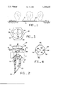
- FIG. 1 is a view of a surface irrigation conduit within which are installed a series of spray devices embodying the principles of the present invention
- FIG. 2 is an enlarged view in elevation and in section with portions broken away showing a single spray device according to the invention
- FIG. 3 is a top view of the spray device of FIG. 2;
- FIG. 4 is a view in section taken along the line 4--4 of FIG. 2, showing the underside of the deflector and the spray pattern produced thereby.
- FIG. 1 shows a typical arrangement for a surface irrigation system wherein a series of spray devices 10 according to the present invention, are installed at spaced apart locations in a conduit 12.
- the conduit which is made of some suitable plastic material such as polyvinyl chloride (PVC), is connected to a source of water under pressure and, as indicated, may lie on the ground surface.
- PVC polyvinyl chloride
- the spray devices are installed in the conduit at whatever spacing is desired so that they can be located to provide the proper moisture pattern around the base of each plant.
- a single spray device 10 comprises a relatively large head portion 14, preferably having a flat sided exterior shape, like a hex nut.
- head portion 14 Extending downwardly from the head portion and integral therewith is a tubular stem portion 16 with a central bore 18. At its lower end this stem portion has a beveled surface 20 which forms a sharp tip 22 that enables the spray device to penetrate a plastic conduit when being installed therein.
- stem portion 16 Extending downwardly from the head portion and integral therewith is a tubular stem portion 16 with a central bore 18. At its lower end this stem portion has a beveled surface 20 which forms a sharp tip 22 that enables the spray device to penetrate a plastic conduit when being installed therein.
- On the exterior of the stem portion just below the head portion are a series of helical threads 24 which further aid in installing the device in a conduit.
- the bore 18 necks down to an axially aligned orifice 26 having a smaller diameter (e.g. 0.039 inches).
- This orifice exits at an opening at the center of the plane upper surface 28 of the hex-shaped head portion, and it is vertically aligned with the center of a deflector 30 spaced above the head portion.
- This deflector is supported by two posts 32 that are integral with and extend upwardly from the top surface 28 of the head portion. These posts are spaced apart dimetrically on the deflector and, as shown in FIG. 4, they have a triangular cross section, each having a innermost knife edge 34 with side walls 36 which diverge outwardly and are interconnected by a curved outer wall 38 that is flush with the curved outer wall of the deflector.
- the deflector itself has generally a circular disc shape with a conical underside 40 that forms the deflecting surface with its apex 42 located along the extended centerline of the orifice 26.
- a series of circumferentially spaced apart serrations or notches 46 are provided around the outer edge of the deflector 30, where its conical deflecting surface 40 meets its outer cylindrical surface 44. These serrations perform an important function in the operation of my spray device 10 in that they serve to break up heavier water droplets and thereby help to produce a uniform spray pattern of relatively fine droplets.
- water is forced upwardly through the orifice 26 as a small stream or jet which impinges directly against the deflector surface apex 42.
- the plastic conduit 12 may be first punched or perforated with an appropriate instrument. Thereafter, the spray device is placed in the opening formed and is pressed and twisted into a secure position with its head portion upright. The location of the spray device and other such devices can then be adjusted to provide the desired spray pattern depending on the plants being irrigated.
- the configuration of my spray device is such that it can be readily produced at high volume in multicavity molds using a suitable plastic such as pvc or nylon and conventional, well-known injection molding techniques. Thus, the unit cost for the device can be kept low.
Landscapes
- Nozzles (AREA)
Abstract
A low volume spray device for irrigation systems has a lower tubular end portion that is beveled to facilitate its insertion into a plastic conduit. Its upper end forms a nozzle portion with a small orifice and a deflector that controls the spray pattern. The device is preferably molded from plastic material so as to be inexpensive yet long lasting.
Description
In the irrigation of certain types of plants and crops it may be preferred to provide a surface distribution of water by means of spray producing nozzles. For example, in orchards such spray devices are desirable if the spray pattern can be controlled in its direction and distribution area, if the flow can be controlled at a low volume rate and if the spray profile can be kept low to avoid water on foliage. To satisfy the need for economy in large irrigation installations, such spray producing devices must be low in cost, yet durable and easy to install without the need for highly skilled and/or time consuming labor. A particular problem arose in providing a spray device that provided a relatively small droplet size in the spray pattern while maintaining adequate flow and without requiring excessive line pressure. Previously developed spray nozzle devices failed to solve all of the aforesaid problems.
A spray nozzle for irrigation systems according to the present invention comprises a one-piece molded plastic device that is adapted to be quickly and easily inserted into a plastic conduit on the ground surface. In general, it comprises a lower tubular portion having external threads and a beveled end surface that enables it to be installed in the sidewall of the plastic conduit through a punctured hole therein.
Integral with the aforesaid lower portion is an upper enlarged head portion having a constricted orifice, and spaced above this head portion is a deflector supported by a pair of post members. This deflector has generally a conical surface with its apex in alignment with the orifice so that a stream of water striking the apex is deflected outwardly in a fan-like pattern. Along the outer edges of the deflector are a series of circumferentially spaced apart serrations or notches which serve to break up the water droplets as they move radially outwardly from the deflector apex. Thus, as water leaves the periphery of the deflector it is broken down into a small droplet size to provide a relatively uniform, fine spray pattern, which is one of the main objects of the present invention.
Another object of the invention is to provide a spray device for surface irrigation systems that is particularly well adapted for ease and economy of manufacture.
Other objects, advantages and features of the present invention will become apparent from the following detailed description of one embodiment thereof, taken in conjunction with the accompanying drawing.
FIG. 1 is a view of a surface irrigation conduit within which are installed a series of spray devices embodying the principles of the present invention;
FIG. 2 is an enlarged view in elevation and in section with portions broken away showing a single spray device according to the invention;
FIG. 3 is a top view of the spray device of FIG. 2; and
FIG. 4 is a view in section taken along the line 4--4 of FIG. 2, showing the underside of the deflector and the spray pattern produced thereby.
With reference to the drawing, FIG. 1 shows a typical arrangement for a surface irrigation system wherein a series of spray devices 10 according to the present invention, are installed at spaced apart locations in a conduit 12. The conduit, which is made of some suitable plastic material such as polyvinyl chloride (PVC), is connected to a source of water under pressure and, as indicated, may lie on the ground surface. The spray devices are installed in the conduit at whatever spacing is desired so that they can be located to provide the proper moisture pattern around the base of each plant.
Turning to FIGS. 2 and 3, a single spray device 10, as shown in detail, comprises a relatively large head portion 14, preferably having a flat sided exterior shape, like a hex nut. Extending downwardly from the head portion and integral therewith is a tubular stem portion 16 with a central bore 18. At its lower end this stem portion has a beveled surface 20 which forms a sharp tip 22 that enables the spray device to penetrate a plastic conduit when being installed therein. On the exterior of the stem portion just below the head portion are a series of helical threads 24 which further aid in installing the device in a conduit.
Within the head portion the bore 18 necks down to an axially aligned orifice 26 having a smaller diameter (e.g. 0.039 inches). This orifice exits at an opening at the center of the plane upper surface 28 of the hex-shaped head portion, and it is vertically aligned with the center of a deflector 30 spaced above the head portion. This deflector is supported by two posts 32 that are integral with and extend upwardly from the top surface 28 of the head portion. These posts are spaced apart dimetrically on the deflector and, as shown in FIG. 4, they have a triangular cross section, each having a innermost knife edge 34 with side walls 36 which diverge outwardly and are interconnected by a curved outer wall 38 that is flush with the curved outer wall of the deflector.
The deflector itself has generally a circular disc shape with a conical underside 40 that forms the deflecting surface with its apex 42 located along the extended centerline of the orifice 26. Around the outer edge of the deflector 30, where its conical deflecting surface 40 meets its outer cylindrical surface 44, are provided a series of circumferentially spaced apart serrations or notches 46. These serrations perform an important function in the operation of my spray device 10 in that they serve to break up heavier water droplets and thereby help to produce a uniform spray pattern of relatively fine droplets. Thus, during such operation, water is forced upwardly through the orifice 26 as a small stream or jet which impinges directly against the deflector surface apex 42. As the water rolls over the conical surface 40 and flows radially away from the apex it strikes the series of peripheral serrations 46 at its outer edge, thereby breaking the surface tension of the water and forming smaller droplets that are propelled outwardly in a uniform spray pattern. Even though the pressure or rate of flow of the water jet through the orifice 26 may vary somewhat, the spray pattern and its droplet size remains relatively constant and uniform. The device will function to provide an acceptable spray pattern even when water pressure is relatively low.
To install the spray device, the plastic conduit 12 may be first punched or perforated with an appropriate instrument. Thereafter, the spray device is placed in the opening formed and is pressed and twisted into a secure position with its head portion upright. The location of the spray device and other such devices can then be adjusted to provide the desired spray pattern depending on the plants being irrigated.
The configuration of my spray device is such that it can be readily produced at high volume in multicavity molds using a suitable plastic such as pvc or nylon and conventional, well-known injection molding techniques. Thus, the unit cost for the device can be kept low.
To those skilled in the art to which this invention relates, many changes in construction and widely differing embodiments and applications of the invention will suggest themselves without departing from the spirit and scope of the invention. The disclosures and the description herein are purely illustrative and are not intended to be in any sense limiting.
Claims (2)
1. An integral, one-piece spray device for use in a surface irrigation system and adapted to be connected to a conduit supplying liquid under pressure, said device comprising:
a head portion having an irregular exterior surface means so that it can be readily gripped for turning when inserted into said conduit;
a lower tubular portion extending downwardly from said head portion, having an axial bore and a beveled lower end;
a deflector means integrally attached to and spaced above said head portion and having a cylindrical outer surface and a smooth conical bottom surface that slopes upwardly and outwardly from a central apex to an outer edge that intersects said outer cylindrical surface;
an orifice in said head portion having a smaller diameter than and being aligned with said bore and also aligned with and spaced from said central apex of said deflector surface; and
a series of small indentations spaced apart along the periphery of said deflector outer edge for decreasing the droplet size of water as it leaves said deflector means.
2. The spray device as described in claim 1 including a pair of integral post members for supporting said deflector means above said head portion, said post members extending upwardly from opposite sides of the upper surface of said head portion, each said post member having a triangular cross section with side surfaces that diverge outwardly toward said outer edge of said deflector means.
Priority Applications (1)
| Application Number | Priority Date | Filing Date | Title |
|---|---|---|---|
| US05/924,289 US4199105A (en) | 1978-07-13 | 1978-07-13 | Low volume spray device for surface irrigation system |
Applications Claiming Priority (1)
| Application Number | Priority Date | Filing Date | Title |
|---|---|---|---|
| US05/924,289 US4199105A (en) | 1978-07-13 | 1978-07-13 | Low volume spray device for surface irrigation system |
Publications (1)
| Publication Number | Publication Date |
|---|---|
| US4199105A true US4199105A (en) | 1980-04-22 |
Family
ID=25450023
Family Applications (1)
| Application Number | Title | Priority Date | Filing Date |
|---|---|---|---|
| US05/924,289 Expired - Lifetime US4199105A (en) | 1978-07-13 | 1978-07-13 | Low volume spray device for surface irrigation system |
Country Status (1)
| Country | Link |
|---|---|
| US (1) | US4199105A (en) |
Cited By (6)
| Publication number | Priority date | Publication date | Assignee | Title |
|---|---|---|---|---|
| USD269034S (en) | 1980-10-27 | 1983-05-17 | Rain Bird Sprinkler Mfg. Corp. | Irrigation spray nozzle |
| US4401273A (en) * | 1981-03-16 | 1983-08-30 | Olson Donald O | Two-piece low volume spray device |
| US4582258A (en) * | 1983-05-09 | 1986-04-15 | Olson Donald O | Two-piece low volume spray device |
| WO1987006859A1 (en) * | 1986-05-06 | 1987-11-19 | James Hardie Building Products Pty. Limited | Jet spray sprinkler |
| DE4300751A1 (en) * | 1993-01-14 | 1994-07-28 | Bernhard Reintanz | Device for spraying liquid, in particular of a lime milk suspension in flue gases from flue gas desulfurization plants of power plants and waste incineration plants of power plants and waste incineration plants |
| DE19819004C2 (en) * | 1998-04-28 | 2001-12-13 | Ingo Scheer | Device for distributing a fluid |
Citations (5)
| Publication number | Priority date | Publication date | Assignee | Title |
|---|---|---|---|---|
| US1674480A (en) * | 1927-09-10 | 1928-06-19 | A M Lockett & Company Ltd | Spray nozzle |
| US2434767A (en) * | 1946-02-16 | 1948-01-20 | George W Hertel | Sprinkler nozzle |
| FR1263654A (en) * | 1960-07-28 | 1961-06-09 | Mannesmann Ag | Sprinkler installation |
| US3779468A (en) * | 1972-07-21 | 1973-12-18 | L Spencer | Trickle irrigation system |
| US3815831A (en) * | 1972-04-19 | 1974-06-11 | A Jooste | Irrigation sprinklers |
-
1978
- 1978-07-13 US US05/924,289 patent/US4199105A/en not_active Expired - Lifetime
Patent Citations (6)
| Publication number | Priority date | Publication date | Assignee | Title |
|---|---|---|---|---|
| US1674480A (en) * | 1927-09-10 | 1928-06-19 | A M Lockett & Company Ltd | Spray nozzle |
| US2434767A (en) * | 1946-02-16 | 1948-01-20 | George W Hertel | Sprinkler nozzle |
| FR1263654A (en) * | 1960-07-28 | 1961-06-09 | Mannesmann Ag | Sprinkler installation |
| US3815831A (en) * | 1972-04-19 | 1974-06-11 | A Jooste | Irrigation sprinklers |
| US3815831B1 (en) * | 1972-04-19 | 1984-12-04 | ||
| US3779468A (en) * | 1972-07-21 | 1973-12-18 | L Spencer | Trickle irrigation system |
Cited By (8)
| Publication number | Priority date | Publication date | Assignee | Title |
|---|---|---|---|---|
| USD269034S (en) | 1980-10-27 | 1983-05-17 | Rain Bird Sprinkler Mfg. Corp. | Irrigation spray nozzle |
| US4401273A (en) * | 1981-03-16 | 1983-08-30 | Olson Donald O | Two-piece low volume spray device |
| US4582258A (en) * | 1983-05-09 | 1986-04-15 | Olson Donald O | Two-piece low volume spray device |
| WO1987006859A1 (en) * | 1986-05-06 | 1987-11-19 | James Hardie Building Products Pty. Limited | Jet spray sprinkler |
| AU583463B2 (en) * | 1986-05-06 | 1989-04-27 | James Hardie Building Products Pty. Limited | Jet spray sprinkler |
| US4889287A (en) * | 1986-05-06 | 1989-12-26 | James Hardie Building Products Pty. Limited | Jet spray sprinkler |
| DE4300751A1 (en) * | 1993-01-14 | 1994-07-28 | Bernhard Reintanz | Device for spraying liquid, in particular of a lime milk suspension in flue gases from flue gas desulfurization plants of power plants and waste incineration plants of power plants and waste incineration plants |
| DE19819004C2 (en) * | 1998-04-28 | 2001-12-13 | Ingo Scheer | Device for distributing a fluid |
Similar Documents
| Publication | Publication Date | Title |
|---|---|---|
| US3266737A (en) | Nozzle head | |
| US4199105A (en) | Low volume spray device for surface irrigation system | |
| US3633826A (en) | Lawn sprinkler | |
| US4055305A (en) | Non-clog water distribution nozzle | |
| US20110198420A1 (en) | Irrigation water bubbler | |
| US4216913A (en) | Method and apparatus for enhancing the distribution of water from an irrigation sprinkler | |
| US1780233A (en) | Sprinkler | |
| US6588680B2 (en) | Spray device for irrigation | |
| US4401273A (en) | Two-piece low volume spray device | |
| US4284241A (en) | Spray nozzle for distribution of liquid which is intended to be affixed transversely to the wall of a conduit | |
| US2631058A (en) | Spray tube for irrigating devices | |
| US4195782A (en) | Method and device for enhancing the distribution of water from a sprinkler operated at low pressures | |
| US4892256A (en) | Up-spray deflector cup for spraying the underside of plant foliage | |
| JP3996715B2 (en) | Irrigation tube and method for producing irrigation tube | |
| US4852806A (en) | Spray structures for use in watering plants | |
| US4477026A (en) | Bubbler head structure | |
| US4391410A (en) | Sprinkler with transversely mounted splash plate | |
| US3034733A (en) | Irrigator | |
| US2521238A (en) | Garden irrigation device | |
| RU2103865C1 (en) | Sectioned sprinkler nozzle | |
| US3682389A (en) | Spinner spray system | |
| US3750956A (en) | Sprinkler unit | |
| US7140557B2 (en) | Emitter tube for irrigation system | |
| US4582258A (en) | Two-piece low volume spray device | |
| US1942395A (en) | Water sprinkler |