US4199075A - Hinge structure for refuse containers - Google Patents

Hinge structure for refuse containers Download PDF

Info

Publication number
US4199075A
US4199075A US05/932,031 US93203178A US4199075A US 4199075 A US4199075 A US 4199075A US 93203178 A US93203178 A US 93203178A US 4199075 A US4199075 A US 4199075A
Authority
US
United States
Prior art keywords
lid
bar
hinge structure
refuse containers
attached
Prior art date
Legal status (The legal status is an assumption and is not a legal conclusion. Google has not performed a legal analysis and makes no representation as to the accuracy of the status listed.)
Expired - Lifetime
Application number
US05/932,031
Inventor
John D. Rohrer
Current Assignee (The listed assignees may be inaccurate. Google has not performed a legal analysis and makes no representation or warranty as to the accuracy of the list.)
PAR-KAN Co
Original Assignee
Parker Industries Inc
Priority date (The priority date is an assumption and is not a legal conclusion. Google has not performed a legal analysis and makes no representation as to the accuracy of the date listed.)
Filing date
Publication date
Application filed by Parker Industries Inc filed Critical Parker Industries Inc
Priority to US05/932,031 priority Critical patent/US4199075A/en
Application granted granted Critical
Publication of US4199075A publication Critical patent/US4199075A/en
Assigned to FLINT & WALLING. INC. reassignment FLINT & WALLING. INC. ASSIGNMENT OF ASSIGNORS INTEREST. Assignors: PARKER INDUSTRIES, INC.,
Assigned to PARKER INDUSTRIES, INC., 101 BRYN MAWR AVENUE, PHILADELPHIA, PA 19010, A CORP. OF DE. reassignment PARKER INDUSTRIES, INC., 101 BRYN MAWR AVENUE, PHILADELPHIA, PA 19010, A CORP. OF DE. ASSIGNMENT OF ASSIGNORS INTEREST. Assignors: FLINT & WALLING, INC., HIGHWAY 15, SILVER LAKE, IN. 46982, A CORP. OF IN.
Assigned to PAR-KAN COMPANY reassignment PAR-KAN COMPANY ASSIGNMENT OF ASSIGNORS INTEREST. Assignors: PARKER INDUSTRIES, INC., A CORP. OF DE
Anticipated expiration legal-status Critical
Expired - Lifetime legal-status Critical Current

Links

Images

Classifications

    • EFIXED CONSTRUCTIONS
    • E05LOCKS; KEYS; WINDOW OR DOOR FITTINGS; SAFES
    • E05FDEVICES FOR MOVING WINGS INTO OPEN OR CLOSED POSITION; CHECKS FOR WINGS; WING FITTINGS NOT OTHERWISE PROVIDED FOR, CONCERNED WITH THE FUNCTIONING OF THE WING
    • E05F1/00Closers or openers for wings, not otherwise provided for in this subclass
    • E05F1/08Closers or openers for wings, not otherwise provided for in this subclass spring-actuated, e.g. for horizontally sliding wings
    • E05F1/10Closers or openers for wings, not otherwise provided for in this subclass spring-actuated, e.g. for horizontally sliding wings for swinging wings, e.g. counterbalance
    • E05F1/12Mechanisms in the shape of hinges or pivots, operated by springs
    • E05F1/123Mechanisms in the shape of hinges or pivots, operated by springs with a torsion bar
    • BPERFORMING OPERATIONS; TRANSPORTING
    • B65CONVEYING; PACKING; STORING; HANDLING THIN OR FILAMENTARY MATERIAL
    • B65FGATHERING OR REMOVAL OF DOMESTIC OR LIKE REFUSE
    • B65F1/00Refuse receptacles; Accessories therefor
    • B65F1/14Other constructional features; Accessories
    • B65F1/16Lids or covers
    • B65F1/1623Lids or covers with means for assisting the opening or closing thereof, e.g. springs
    • BPERFORMING OPERATIONS; TRANSPORTING
    • B65CONVEYING; PACKING; STORING; HANDLING THIN OR FILAMENTARY MATERIAL
    • B65FGATHERING OR REMOVAL OF DOMESTIC OR LIKE REFUSE
    • B65F1/00Refuse receptacles; Accessories therefor
    • B65F1/14Other constructional features; Accessories
    • B65F1/16Lids or covers
    • B65F1/1646Lids or covers provided with means for mounting on receptacles, e.g. hinges
    • EFIXED CONSTRUCTIONS
    • E05LOCKS; KEYS; WINDOW OR DOOR FITTINGS; SAFES
    • E05YINDEXING SCHEME ASSOCIATED WITH SUBCLASSES E05D AND E05F, RELATING TO CONSTRUCTION ELEMENTS, ELECTRIC CONTROL, POWER SUPPLY, POWER SIGNAL OR TRANSMISSION, USER INTERFACES, MOUNTING OR COUPLING, DETAILS, ACCESSORIES, AUXILIARY OPERATIONS NOT OTHERWISE PROVIDED FOR, APPLICATION THEREOF
    • E05Y2999/00Subject-matter not otherwise provided for in this subclass
    • YGENERAL TAGGING OF NEW TECHNOLOGICAL DEVELOPMENTS; GENERAL TAGGING OF CROSS-SECTIONAL TECHNOLOGIES SPANNING OVER SEVERAL SECTIONS OF THE IPC; TECHNICAL SUBJECTS COVERED BY FORMER USPC CROSS-REFERENCE ART COLLECTIONS [XRACs] AND DIGESTS
    • Y10TECHNICAL SUBJECTS COVERED BY FORMER USPC
    • Y10STECHNICAL SUBJECTS COVERED BY FORMER USPC CROSS-REFERENCE ART COLLECTIONS [XRACs] AND DIGESTS
    • Y10S220/00Receptacles
    • Y10S220/908Trash container

Definitions

  • a refuse container commonly used in industrial plants, businesses and institutions, and by apartments and hotels and similar commercial enterprises consists of a generally rectangular container body of steel plate construction, and a plate-like steel lid hinged to an upper rear edge of the body.
  • the container is relatively large and heavy and is left at the establishment for accumulation of refuse, and is emptied from time to time by a refuse truck using a mechanical power lift which elevates and inverts the container to dump the contents therefrom into the truck.
  • a refuse truck using a mechanical power lift which elevates and inverts the container to dump the contents therefrom into the truck.
  • the lid is heavy and often difficult and possibly unsafe for one person to open when refuse is to be dumped into the container and thereafter when the contents are to be dumped into the truck.
  • Another object of the present invention is to provide a refuse container having a plate-like lid hinged to an uppeer edge of the container body, in which a mechanism for assisting in raising the lid is incorporated in the hinge structure and forms a part of the pivot mechanism of the hinge, and which can be opened to its fully opened position without interference from the assist mechanism for dumping the contents from the container.
  • Still another object is to provide a hinge structure for the lid of the aforementioned type of refuse container which employs one or more torque bars forming the pivot pin of the hinge, and which is so designed and constructed that the hinge structure is mostly enclosed by the margin of the lid and hence is protected from dirt and weather to give long trouble free service.
  • a further object of the invention is to provide a refuse container of the type designed and built to be emptied by a power mechanism on a refuse pick-up truck, the lid of which can be easily opened and safely used by one person when dumping refuse into the container, and which provides maximum safety to other persons using or otherwise handling or being around the container.
  • FIG. 1 is a perspective view of a refuse container embodying the present invention
  • FIG. 2 is an enlarged fragmentary perspective view of the hinge and lid assist structure shown in FIG. 1, the portion shown being identified in FIG. 1 by the broken line circle;
  • FIG. 3 is a side elevational view of the refuse container shown in FIG. 1 with the lid thereof in fully opened position;
  • FIG. 4 is a fragmentary side elevational view of the refuse container showing the lid in a partially opened position
  • FIG. 5 is a fragmentary side elevational view of the refuse container showing the lid in its fully closed position
  • FIG. 6 is an exploded perspective view of a portion of the refuse container and hinge and lid assist structure.
  • FIG. 1 designates a refuse container of the type normally used for large commercial and industrial establishments, apartment houses, dormitories and the like, and which is emptied by a refuse truck which lifts and inverts the container to dump the contents thereof into the truck bed.
  • the container includes a pick-up arm 12 at each end for engagement by the lift mechanism of the truck when the container is to be emptied.
  • the container may be mounted on casters (not shown) and may include a lid 14 connected to body 16 by a hinge structure 18.
  • the body and the lid are constructed of heavy sheet metal to form a generally rectangular container structure.
  • the containers may be of different sizes; however, the structures are similar in cnstruction and operation.
  • the lid which is relatively heavy, normally contains one or more handles along the front or side edges and, in order to provide the required sturdiness and durability, it is constructed of relatively thick sheet or plate metal and, in the embodiment shown, contains a plurality of ribs 20. In view of the thickness and size of the lid structure, it is heavy and difficult to open, particularly since it is relatively large and cannot be easily handled.
  • the primary feature of the present invention is the hinge and lid assist structure, indicated generally by numeral 18, which is disposed along the upper edge of the back of the body 16 and includes upright fixtures 22 and 24 at the opposite ends of the upper edge of the body, the two fixtures being rigidly secured by welding or other suitable connecting means to the body.
  • the cover 14 is pivotally connected to the two fixtures by torque bars 30 and 31 extending parallel to the rear edge of the lid and being pivotally connected thereto by blocks 32 at each end.
  • the two blocks 32 are secured to the cover by an inverted U-shaped flange 34, preferably formed integrally with the rear edge of the cover, and the blocks 32 are welded or otherwise secured in the respective ends of channel 36 of the U-shaped flange.
  • the two blocks contain openings for bars 30 and 31 and the lid can rotate relative to the bars at the opposite ends, so that the lid will pivot to its fully closed position shown in FIG. 5.
  • the lid is hinged to the body and can be swung from its closed position to its fully opened position when refuse is to be removed from the container. In normal use, the lid is raised only to a partially opened position for the purpose of dumping refuse into the container.
  • the torque bars 30 and 31 are square in cross section and the inner ends seats in blocks 40 and 42 mounted in U-shaped flange 34 and held therein from rotating by the square configuration of the blocks, which fit sufficiently close to the walls of the flange to prevent rotation of the blocks within the flange. Since blocks 40 and 42, which are disposed near the lengthwise center of the flange, are non-rotatable, and the holes through the blocks are of a square cross section substantially the same size as the dimension of bars 30 and 31, the movement of the lid between opened and closed positions rotates the bars.
  • the outer end of each end of the bars passes through a sleeve 44 in fixtures 22 and 24, and extends downwardly at right angles, as seen in FIG. 2, to form a finger 50.
  • each finger seats in the respective brackets 52 and 54 at the right and left hand ends of the refuse container as viewed in FIG. 1, the brackets forming a stop or abutment for the fingers.
  • the fingers 50 engage the rear wall 56 of the brackets and hence prevent the bars from rotating further with the lid. Further movement of the lid twists the bars, thereby restraining the closing movement of the lid.
  • the resilient force contained in the torque bars assists in lifting the lid so that substantially less force is required to raise the lid to an elevated position than is normally required with the lid of a conventional refuse container.
  • the torque bars may be connected at their inner ends to form a continuous bar along the rear of the lid.
  • the refuse container can now be easily emptied by a refuse truck lifting and inverting the container. After the emptied container has been returned to its upright position, the lid is then rotated on the hinge formed in part by the torque bars to its fully closed position. As the lid is moved from a predetermined point in the closing direction, the fingers engage the rear wall 56 and again apply a twisting action to each end section of the torque bar assembly.
  • the present refuse container lid and hinge concept forms a hinge structure having a compact resilient lift assist mechanism incorporated therein.
  • the lid assist structure is essentially enclosed except for the two fingers 50, and no dangerous elements such as springs and levers, which could injure someone handling the container, are exposed. Further, the assist prevents the lid, which is relatively heavy, from falling unrestrained to its closed position where it could cause serious injury to someone closing the container or opening the container to empty refuse therein.

Landscapes

  • Engineering & Computer Science (AREA)
  • Mechanical Engineering (AREA)
  • Refuse Receptacles (AREA)

Abstract

A hinge structure for refuse containers having a body and a top opening and a lid for the opening, in which the lid is attached to the body by a hinge structure having a torque bar therein for assisting in the opening of the lid. The torque bar runs along the back of the lid and has laterally extending ends which engage abutments on the body to apply torque to cause the bar to exert a lifting force to the lid. The ends disengage the abutments after the lid has been opened to a predetermined point so that the lid can be easily and fully opened without the torque bar interfering with the full opening of the lid. The lid can be easily lifted to empty refuse into the container and will fully reclose itself notwithstanding the restraining effect of the torque bar.

Description

A refuse container commonly used in industrial plants, businesses and institutions, and by apartments and hotels and similar commercial enterprises, consists of a generally rectangular container body of steel plate construction, and a plate-like steel lid hinged to an upper rear edge of the body. The container is relatively large and heavy and is left at the establishment for accumulation of refuse, and is emptied from time to time by a refuse truck using a mechanical power lift which elevates and inverts the container to dump the contents therefrom into the truck. In view of the large capacity of these refuse containers, they are made sturdy, and the lid is heavy and often difficult and possibly unsafe for one person to open when refuse is to be dumped into the container and thereafter when the contents are to be dumped into the truck. It is therefore one of the principal objects of the present invention to provide a mechanism for use with the lid of a refuse container which will assist in lifting the lid to its opened position, and which is compact and simple in construction and can effectively be installed on the standard or conventional refuse containers of the aforesaid type without making any substantial changes in the construction of the container.
Another object of the present invention is to provide a refuse container having a plate-like lid hinged to an uppeer edge of the container body, in which a mechanism for assisting in raising the lid is incorporated in the hinge structure and forms a part of the pivot mechanism of the hinge, and which can be opened to its fully opened position without interference from the assist mechanism for dumping the contents from the container.
Still another object is to provide a hinge structure for the lid of the aforementioned type of refuse container which employs one or more torque bars forming the pivot pin of the hinge, and which is so designed and constructed that the hinge structure is mostly enclosed by the margin of the lid and hence is protected from dirt and weather to give long trouble free service.
A further object of the invention is to provide a refuse container of the type designed and built to be emptied by a power mechanism on a refuse pick-up truck, the lid of which can be easily opened and safely used by one person when dumping refuse into the container, and which provides maximum safety to other persons using or otherwise handling or being around the container.
Additional objects and advantages of the present invention will become apparent from the following description and accompanying drawings, wherein:
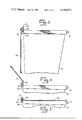
FIG. 1 is a perspective view of a refuse container embodying the present invention;
FIG. 2 is an enlarged fragmentary perspective view of the hinge and lid assist structure shown in FIG. 1, the portion shown being identified in FIG. 1 by the broken line circle;
FIG. 3 is a side elevational view of the refuse container shown in FIG. 1 with the lid thereof in fully opened position;
FIG. 4 is a fragmentary side elevational view of the refuse container showing the lid in a partially opened position;
FIG. 5 is a fragmentary side elevational view of the refuse container showing the lid in its fully closed position; and
FIG. 6 is an exploded perspective view of a portion of the refuse container and hinge and lid assist structure.
Referring more specifically to the drawings, FIG. 1 designates a refuse container of the type normally used for large commercial and industrial establishments, apartment houses, dormitories and the like, and which is emptied by a refuse truck which lifts and inverts the container to dump the contents thereof into the truck bed. The container, as shown, includes a pick-up arm 12 at each end for engagement by the lift mechanism of the truck when the container is to be emptied. The container may be mounted on casters (not shown) and may include a lid 14 connected to body 16 by a hinge structure 18. The body and the lid are constructed of heavy sheet metal to form a generally rectangular container structure. The containers may be of different sizes; however, the structures are similar in cnstruction and operation. The lid, which is relatively heavy, normally contains one or more handles along the front or side edges and, in order to provide the required sturdiness and durability, it is constructed of relatively thick sheet or plate metal and, in the embodiment shown, contains a plurality of ribs 20. In view of the thickness and size of the lid structure, it is heavy and difficult to open, particularly since it is relatively large and cannot be easily handled.
The primary feature of the present invention is the hinge and lid assist structure, indicated generally by numeral 18, which is disposed along the upper edge of the back of the body 16 and includes upright fixtures 22 and 24 at the opposite ends of the upper edge of the body, the two fixtures being rigidly secured by welding or other suitable connecting means to the body. The cover 14 is pivotally connected to the two fixtures by torque bars 30 and 31 extending parallel to the rear edge of the lid and being pivotally connected thereto by blocks 32 at each end. The two blocks 32 are secured to the cover by an inverted U-shaped flange 34, preferably formed integrally with the rear edge of the cover, and the blocks 32 are welded or otherwise secured in the respective ends of channel 36 of the U-shaped flange. The two blocks contain openings for bars 30 and 31 and the lid can rotate relative to the bars at the opposite ends, so that the lid will pivot to its fully closed position shown in FIG. 5. Thus the lid is hinged to the body and can be swung from its closed position to its fully opened position when refuse is to be removed from the container. In normal use, the lid is raised only to a partially opened position for the purpose of dumping refuse into the container.
The torque bars 30 and 31 are square in cross section and the inner ends seats in blocks 40 and 42 mounted in U-shaped flange 34 and held therein from rotating by the square configuration of the blocks, which fit sufficiently close to the walls of the flange to prevent rotation of the blocks within the flange. Since blocks 40 and 42, which are disposed near the lengthwise center of the flange, are non-rotatable, and the holes through the blocks are of a square cross section substantially the same size as the dimension of bars 30 and 31, the movement of the lid between opened and closed positions rotates the bars. The outer end of each end of the bars passes through a sleeve 44 in fixtures 22 and 24, and extends downwardly at right angles, as seen in FIG. 2, to form a finger 50. The lower end of each finger seats in the respective brackets 52 and 54 at the right and left hand ends of the refuse container as viewed in FIG. 1, the brackets forming a stop or abutment for the fingers. When the lid is moved toward closed position, the fingers 50 engage the rear wall 56 of the brackets and hence prevent the bars from rotating further with the lid. Further movement of the lid twists the bars, thereby restraining the closing movement of the lid. When the lid is opened, the resilient force contained in the torque bars assists in lifting the lid so that substantially less force is required to raise the lid to an elevated position than is normally required with the lid of a conventional refuse container. If desired the torque bars may be connected at their inner ends to form a continuous bar along the rear of the lid.
When the lid is opened to the fully opened position as seen in FIG. 3, interference by the torque bars is avoided by permitting movement of fingers 50 away from the rear wall 56 as the lid is moved past a predetermined opened position. As the fingers swing away from the rear wall of the brackets, they pass through the forward opened side 58 of the brackets and rotate as the lid is opened further, thus applying no further torque or assistance to the lid as the lid is moved from the predetermined position to its fully opened position. As the lid is closed and the predetermined position of the lid is reached in the closing direction, the fingers 50 at the opposite ends of the lid engage rear wall 56 of bracket 52 and apply increasing resistance or restraining force to the closing movement of the lid, the force, however, being insufficient to prevent fully closing the lid.
In the operation of the present refuse container and lid structure, with the lid 14 assembled on body 16 in the manner illustrated in FIGS. 1 and 2, and with the lid closed, fingers 50 engage wall 56 of brackets 52 and 54 at the opposite ends of the rear side of the lid. Since the fingers engage the wall before the lid is fully closed, the torque bars 30 and 31 are twisted sufficiently to resiliently resist the closing of the lid. When the lid is to be opened, the forward edge is raised and the lifting is assisted by the resilient force contained in the twisted torque bars, the lid being assisted to the point where fingers 50 no longer contact rear wall 56. Thereafter, if the lid is opened further, the fingers swing forwardly and will pass the front wall of brackets 52 and 54 permitting the lid to move to its fully opened position as illustrated in FIG. 3 without interference from fingers 50 or the torque bars. The refuse container can now be easily emptied by a refuse truck lifting and inverting the container. After the emptied container has been returned to its upright position, the lid is then rotated on the hinge formed in part by the torque bars to its fully closed position. As the lid is moved from a predetermined point in the closing direction, the fingers engage the rear wall 56 and again apply a twisting action to each end section of the torque bar assembly.
It is thus seen that the present refuse container lid and hinge concept forms a hinge structure having a compact resilient lift assist mechanism incorporated therein. The lid assist structure is essentially enclosed except for the two fingers 50, and no dangerous elements such as springs and levers, which could injure someone handling the container, are exposed. Further, the assist prevents the lid, which is relatively heavy, from falling unrestrained to its closed position where it could cause serious injury to someone closing the container or opening the container to empty refuse therein.
While only one embodiment of the present refuse container lid structure has been described in detail herein, various changes and modifications may be made without departing from the scope of the invention.

Claims (10)

I claim:
1. A hinge structure for refuse containers having a body with a top opening and a lid for the opening: said hinge structure comprising a fixture disposed at each end at the upper rear corners of the body and having a hole therethrough, a torque bar means extending along the rear side of the lid and extending through the holes in said fixtures, finger means attached to each end of the torque bar means and extending substantially at right angles thereto, spaced pivot means attached to said lid near said fixtures and being rotatable on said bar means as said lid is opened and closed, means disposed between said spaced pivot means for preventing relative rotation between the lid and said bar means in a section spaced from said pivot means, an abutment on said body at each end of said bar means forming a stop for said fingers to limit the rotation of the end sections of said bar means and thereby causing said bar means to apply a force tending to open said lid, said abutments being mounted rigidly on said body adjacent the rear edge thereof and so disposed relative to said fingers that said fingers move away from said abutments when the lid is partially opened, such that said bar means assists only the initial opening of the lid and resists only the final closing of said lid.
2. A hinge structure for refuse containers as defined in claim 1 in which said lid has a U-shaped flange along the rear edge thereof and said torque bar means is disposed in said flange.
3. A hinge structure for refuse containers as defined in claim 2 in which said spaced pivot means attached to said lid consists of blocks disposed at each end of said U-shaped flange and containing holes for said bar means.
4. A hinge structure for refuse containers as defined in claim 3 in which said means disposed between said spaced pivot means consists of a block-like means near the center of said bar means within said U-shaped flange, said flange holding said block from rotating relative to said lid.
5. A hinge structure for refuse containers as defined in claim 4 in which said torque bar means consists of longitudinal sections and is square in cross section and said fingers are attached integrally to the ends of said bar sections.
6. A hinge structure for refuse containers as defined in claim 1 in which said torque bar means consists of two longitudinal sections and is square in cross section and said fingers are attached integrally to the ends of said bar sections.
7. A hinge structure for refuse containers having a body with a top opening and a lid for the opening: said hinge structure comprising a fixture disposed at each end of the upper rear corners of the body and being pivotally connected to the lid, a torque bar attached to said lid in spaced relation to one of said fixtures, a radially extending means adjacent said one fixture, an abutment engageable by said radially extending means on the body for limiting the rotational movement of the end of said torque bar near said one fixture only as said lid is moved toward closed position to cause said bar to assist only the initial opening of said lid and to resist only the final closing of said lid.
8. A hinge structure for refuse containers as defined in claim 7 in which a flange is attached to the rear edge of said lid and substantially encloses said torque bar.
9. A hinge structure for refuse containers as defined in claim 7 in which said means is a finger rigidly attached to the end of said bar adjacent one of said fixtures, and said abutment is so disposed relative to said finger that said finger moves away from said abutment when the lid is partially opened.
10. A hinge structure for refuse containers as defined in claim 9 in which a flange is attached to the rear edge of said lid and substantially encloses said torque bar.
US05/932,031 1978-08-08 1978-08-08 Hinge structure for refuse containers Expired - Lifetime US4199075A (en)

Priority Applications (1)

Application Number Priority Date Filing Date Title
US05/932,031 US4199075A (en) 1978-08-08 1978-08-08 Hinge structure for refuse containers

Applications Claiming Priority (1)

Application Number Priority Date Filing Date Title
US05/932,031 US4199075A (en) 1978-08-08 1978-08-08 Hinge structure for refuse containers

Publications (1)

Publication Number Publication Date
US4199075A true US4199075A (en) 1980-04-22

Family

ID=25461666

Family Applications (1)

Application Number Title Priority Date Filing Date
US05/932,031 Expired - Lifetime US4199075A (en) 1978-08-08 1978-08-08 Hinge structure for refuse containers

Country Status (1)

Country Link
US (1) US4199075A (en)

Cited By (14)

* Cited by examiner, † Cited by third party
Publication number Priority date Publication date Assignee Title
US4342402A (en) * 1981-05-14 1982-08-03 Dymar Industries, Inc. Refuse container cover
US4676431A (en) * 1986-12-17 1987-06-30 Teske John E Trash container
US4846536A (en) * 1986-06-30 1989-07-11 Kabushiki Kaisha Toshiba Portable apparatus
US4949866A (en) * 1989-02-07 1990-08-21 Sanders Glen D Refuse container cover
US5088616A (en) * 1990-10-11 1992-02-18 Cadillac Products, Inc. Cover for use with a receptacle
DE4138314A1 (en) * 1990-11-21 1992-06-25 Nhk Spring Co Ltd Rotary hinge for slow pivot movement of cover
DE4138323A1 (en) * 1990-11-21 1992-06-25 Nhk Spring Co Ltd Slow acting rotary shaft mechanism
DE4138316A1 (en) * 1990-11-21 1992-07-02 Nhk Spring Co Ltd Low speed rotary shaft set contg. grease
WO1997033803A1 (en) * 1996-03-11 1997-09-18 Peter John Tasker Catch, hinge, lid assembly and container incorporating
USD511084S1 (en) * 2003-04-08 2005-11-01 Maria Georgopoulos Door hinge
US20090071957A1 (en) * 2007-09-13 2009-03-19 Chih-Chen Chang Safety Box
US20140306465A1 (en) * 2013-04-15 2014-10-16 Joseph Daniel KREITZER Automatic locking apparatus
US8905257B2 (en) 2012-05-24 2014-12-09 Wastequip, Llc Grease container
WO2015110649A3 (en) * 2014-01-27 2015-09-11 Desacon Gmbh Container, in particular a dumpster, waste container or roll-off container

Citations (8)

* Cited by examiner, † Cited by third party
Publication number Priority date Publication date Assignee Title
US2602957A (en) * 1945-04-02 1952-07-15 Winters & Crampton Corp Hinge construction
US2904853A (en) * 1959-01-16 1959-09-22 Philco Corp Cabinet structure
US3061871A (en) * 1960-09-14 1962-11-06 Whirlpool Co Torsion bar hinge structure
US3136575A (en) * 1962-06-11 1964-06-09 Byron M Kolling Refuse container
US3476375A (en) * 1967-01-17 1969-11-04 Simca Automobiles Sa Torsion bar adjusting device
US3955241A (en) * 1975-10-16 1976-05-11 Weber-Knapp Company Cam operated spring biased counterbalance hinge mechanism for cabinet lid or the like
US4119195A (en) * 1975-05-19 1978-10-10 Widener Charles D Protective case
US4133074A (en) * 1977-08-03 1979-01-09 Schack John B Spring assisted door construction

Patent Citations (8)

* Cited by examiner, † Cited by third party
Publication number Priority date Publication date Assignee Title
US2602957A (en) * 1945-04-02 1952-07-15 Winters & Crampton Corp Hinge construction
US2904853A (en) * 1959-01-16 1959-09-22 Philco Corp Cabinet structure
US3061871A (en) * 1960-09-14 1962-11-06 Whirlpool Co Torsion bar hinge structure
US3136575A (en) * 1962-06-11 1964-06-09 Byron M Kolling Refuse container
US3476375A (en) * 1967-01-17 1969-11-04 Simca Automobiles Sa Torsion bar adjusting device
US4119195A (en) * 1975-05-19 1978-10-10 Widener Charles D Protective case
US3955241A (en) * 1975-10-16 1976-05-11 Weber-Knapp Company Cam operated spring biased counterbalance hinge mechanism for cabinet lid or the like
US4133074A (en) * 1977-08-03 1979-01-09 Schack John B Spring assisted door construction

Cited By (16)

* Cited by examiner, † Cited by third party
Publication number Priority date Publication date Assignee Title
US4342402A (en) * 1981-05-14 1982-08-03 Dymar Industries, Inc. Refuse container cover
US4846536A (en) * 1986-06-30 1989-07-11 Kabushiki Kaisha Toshiba Portable apparatus
US4676431A (en) * 1986-12-17 1987-06-30 Teske John E Trash container
US4949866A (en) * 1989-02-07 1990-08-21 Sanders Glen D Refuse container cover
US5088616A (en) * 1990-10-11 1992-02-18 Cadillac Products, Inc. Cover for use with a receptacle
DE4138314A1 (en) * 1990-11-21 1992-06-25 Nhk Spring Co Ltd Rotary hinge for slow pivot movement of cover
DE4138323A1 (en) * 1990-11-21 1992-06-25 Nhk Spring Co Ltd Slow acting rotary shaft mechanism
DE4138316A1 (en) * 1990-11-21 1992-07-02 Nhk Spring Co Ltd Low speed rotary shaft set contg. grease
WO1997033803A1 (en) * 1996-03-11 1997-09-18 Peter John Tasker Catch, hinge, lid assembly and container incorporating
USD511084S1 (en) * 2003-04-08 2005-11-01 Maria Georgopoulos Door hinge
US20090071957A1 (en) * 2007-09-13 2009-03-19 Chih-Chen Chang Safety Box
US8905257B2 (en) 2012-05-24 2014-12-09 Wastequip, Llc Grease container
US9783363B2 (en) 2012-05-24 2017-10-10 Wastequip, Llc Grease container and lid for the same
US20140306465A1 (en) * 2013-04-15 2014-10-16 Joseph Daniel KREITZER Automatic locking apparatus
US9303439B2 (en) * 2013-04-15 2016-04-05 Joseph Daniel KREITZER Automatic locking apparatus
WO2015110649A3 (en) * 2014-01-27 2015-09-11 Desacon Gmbh Container, in particular a dumpster, waste container or roll-off container

Similar Documents

Publication Publication Date Title
US4199075A (en) Hinge structure for refuse containers
US4609117A (en) Waste container
US5474341A (en) Gravity actuated container lock
AU622536B2 (en) Waste container
US4456141A (en) Waste containers
US6702135B2 (en) Universal dumpster
US4836394A (en) Refuse container with two-position lid
US4186844A (en) Easy opening trash bin lid
US5150806A (en) Refuse container with two-position lid
US9580243B2 (en) Locking device for waste container
US4878596A (en) Waste bin lid
US5085341A (en) Trash bin system
US4405278A (en) Self-emptying dump box
US8146767B1 (en) Trash container
US7083060B2 (en) Universal dumpster
CN102985343B (en) Covers and boxes fitted with such covers
US4299419A (en) Fireplace ash cleaning shovel
US3984017A (en) Self-emptying container
KR20170043490A (en) Trash can for weighted system envelope
US1939139A (en) Waste receptacle
JP2919746B2 (en) Garbage bin
CN213010010U (en) Contact-free bidirectional opening and closing garbage can
JPH0688604B2 (en) Sealed container with lid opening / closing device
US2943754A (en) Vehicular dumping receptacle
US3161300A (en) Drop bottom container having latch means therefor

Legal Events

Date Code Title Description
AS Assignment

Owner name: FLINT & WALLING. INC., HIGHWAY 15, SILVER LAKE, IN

Free format text: ASSIGNMENT OF ASSIGNORS INTEREST.;ASSIGNOR:PARKER INDUSTRIES, INC.,;REEL/FRAME:003917/0439

Effective date: 19811019

AS Assignment

Owner name: PARKER INDUSTRIES, INC., 101 BRYN MAWR AVENUE, PHI

Free format text: ASSIGNMENT OF ASSIGNORS INTEREST.;ASSIGNOR:FLINT & WALLING, INC., HIGHWAY 15, SILVER LAKE, IN. 46982, A CORP. OF IN.;REEL/FRAME:004494/0657

Effective date: 19851004

AS Assignment

Owner name: PAR-KAN COMPANY, P.O. BOX 219, SILVER LAKE, IN 469

Free format text: ASSIGNMENT OF ASSIGNORS INTEREST.;ASSIGNOR:PARKER INDUSTRIES, INC., A CORP. OF DE;REEL/FRAME:005652/0819

Effective date: 19901126