US4184665A - Thermally actuated wedge block - Google Patents
Thermally actuated wedge block Download PDFInfo
- Publication number
- US4184665A US4184665A US05/967,665 US96766578A US4184665A US 4184665 A US4184665 A US 4184665A US 96766578 A US96766578 A US 96766578A US 4184665 A US4184665 A US 4184665A
- Authority
- US
- United States
- Prior art keywords
- wedge
- wedge block
- thermal expansion
- tapered surfaces
- members
- Prior art date
- Legal status (The legal status is an assumption and is not a legal conclusion. Google has not performed a legal analysis and makes no representation as to the accuracy of the status listed.)
- Expired - Lifetime
Links
- 239000000463 material Substances 0.000 claims abstract description 10
- XAGFODPZIPBFFR-UHFFFAOYSA-N aluminium Chemical compound [Al] XAGFODPZIPBFFR-UHFFFAOYSA-N 0.000 claims description 3
- 229910052782 aluminium Inorganic materials 0.000 claims description 3
- 229910000990 Ni alloy Inorganic materials 0.000 claims description 2
- 239000012080 ambient air Substances 0.000 claims 2
- 238000012360 testing method Methods 0.000 description 6
- 229910001374 Invar Inorganic materials 0.000 description 3
- 238000001816 cooling Methods 0.000 description 1
- 230000007423 decrease Effects 0.000 description 1
- 230000000694 effects Effects 0.000 description 1
- 230000004927 fusion Effects 0.000 description 1
- 230000002285 radioactive effect Effects 0.000 description 1
Images
Classifications
-
- B—PERFORMING OPERATIONS; TRANSPORTING
- B66—HOISTING; LIFTING; HAULING
- B66F—HOISTING, LIFTING, HAULING OR PUSHING, NOT OTHERWISE PROVIDED FOR, e.g. DEVICES WHICH APPLY A LIFTING OR PUSHING FORCE DIRECTLY TO THE SURFACE OF A LOAD
- B66F19/00—Hoisting, lifting, hauling or pushing, not otherwise provided for
-
- F—MECHANICAL ENGINEERING; LIGHTING; HEATING; WEAPONS; BLASTING
- F16—ENGINEERING ELEMENTS AND UNITS; GENERAL MEASURES FOR PRODUCING AND MAINTAINING EFFECTIVE FUNCTIONING OF MACHINES OR INSTALLATIONS; THERMAL INSULATION IN GENERAL
- F16M—FRAMES, CASINGS OR BEDS OF ENGINES, MACHINES OR APPARATUS, NOT SPECIFIC TO ENGINES, MACHINES OR APPARATUS PROVIDED FOR ELSEWHERE; STANDS; SUPPORTS
- F16M7/00—Details of attaching or adjusting engine beds, frames, or supporting-legs on foundation or base; Attaching non-moving engine parts, e.g. cylinder blocks
Definitions
- the Large Coil Test Facility (LCTF) of the Oak Ridge National Laboratory will be utilized for the testing and development of large superconducting magnet coils for future tokamak devices.
- LCTF Large Coil Test Facility
- the wedge blocks Upon cooling of the test stand to its cryogenic operating temperature, the wedge blocks should be adapted to expand in thickness to eliminate their clearances between structural members and be able to withstand high compressive loads for as long as may be required. On warm-up back to room temperature, the wedge blocks should then be adapted to retract to their initial dimensions.
- the present invention was conceived to meet this need in a manner to be described hereinbelow.
- the above object has been accomplished in the present invention by providing a double wedge configuration comprising an inner tapered member fitted within a pair of reversed-tapered outer members all fitted together by means of a high thermal expansion tension rod, with the wedging parts (said members) being made from a low coefficient of thermal expansion material.
- FIG. 1 is a schematic illustration of a conventional wedge block of the prior art
- FIG. 2 is a schematic illustration of an automatic wedge block of the present invention
- FIG. 3 is a schematic illustration of another embodiment of the present invention.
- FIG. 4 is a sectional side view of the embodiment of FIG. 3.
- FIG. 1 With reference first to the prior art of FIG. 1, a simple conventional wedge block for manual actuation is shown.
- the wedging action depends on the loosening or tightening of the nut A on the bolt B which changes the thickness T of the assembly by sliding the two wedges W on one another.
- the overall length L of the wedge also increases or decreases as the thickness is changed.
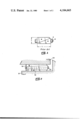
- FIG. 2 of the drawings there is shown one embodiment of a wedge block of the present invention.
- a tapered wedge member 16 fits within two tapered wedge members 15, 17.
- a tension rod 18, provided with a suitable head, extends through an end plate 19, then through an axial hole in the wedge member 16, and is secured by means of a nut 22 exterior of the end of member 16, as shown.
- the end plate 19 rests against the ends of the wedge members 15, 17 and supports the head of the rod 18.
- the wedge block of FIG. 2 is effectively a double wedge, that is, its change in thickness will be twice that of the simple wedge of FIG. 1 for the same wedge angle.
- the wedging parts 15, 16, 17 are made from a low coefficient of thermal expansion material such as the nickel alloy (Invar 36), for example.
- the tension rod 18, on the other hand, is made from a high thermal expansion material such as aluminum, for example.
- the wedge block of FIG. 2 is positioned between any two desired structural members 20 and 21 of the test stand, and at room temperature the wedging members 15, 16, 17 of the wedge block are maintained in intimate contact with each other by means of the plate 19, the tension rod 18 and the nut 22 while at the same time providing the desired clearances between the exterior surfaces of the wedge members 15, 17 and the interior surfaces of the structural members 20, 21.
- the tension rod 18 will contract axially to automatically effect the movement of the wedge member 16 toward the end plate 19 thus expanding the thickness of the wedge block into intimate structural contact with the members 20, 21.
- the tension rod 18 will expand axially to permit the wedge block to contract in thickness.
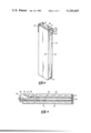
- FIGS. 3 and 4 illustrate another embodiment of the present invention which will now be described.
- the device of FIGS. 3 and 4 operates on the same principle as the device of FIG. 2 described above.
- FIGS. 3 and 4 the wedging surface of the interior Invar wedge member (or driver) 24 is broken up into a series of small angled surfaces, as shown, which considerably reduces the wedge thickness.
- two aluminum tension rods 13 and 14 are provided and extend through suitable holes in the inner wedge member 24 (see FIG. 4 for the rod 14). It should be understood that the device of FIGS. 3 and 4 could be provided with a single tension rod, if such is desired, as in the FIG. 2 device.
- the wedge member 24 fits within the two outer Invar wedge members 23, 25 which are provided with internal tapered surfaces to match the angled surfaces of the wedge member 24 as shown.
- An end plate 26 (FIG. 4) rests against the end of the wedge member 24 and the tension rods 13, 14 with suitable heads abutting against the end plate extend through the plate 26, through the wedge member 24, through another end plate 27 and are secured by means of respective nuts 28 to maintain the wedge members 23-25 in intimate contact each with the others.
- the end plate 27 rests in suitable slots in the respective wedge members 23 and 25 such that the temperature changes, the tension rods 13, 14 will either contract or expand in the same manner as the device of FIG. 2 to provide the desired wedging action.
- a pair of respective retaining plates 32 (FIG.
- a practical wedge angle for the device of FIGS. 3 and 4 is twenty degrees, for example, and by breaking up the wedging surface into a series of small angled surfaces, as mentioned above, provides for a reduction in the wedge thickness.
- the wedge illustrated in FIGS. 3 and 4 is only 1.575 inches thick at room temperature, and at 4° K. it expands to 1.678 inches. The corresponding change in the length of the wedge is only 0.156 inch.
Landscapes
- Engineering & Computer Science (AREA)
- General Engineering & Computer Science (AREA)
- Mechanical Engineering (AREA)
- Life Sciences & Earth Sciences (AREA)
- Geology (AREA)
- Structural Engineering (AREA)
- Connection Of Plates (AREA)
Abstract
This invention relates to an automatically-operating wedge block for maintaining intimate structural contact over wide temperature ranges, including cryogenic use. The wedging action depends on the relative thermal expansion of two materials having very different coefficients of thermal expansion. The wedge block expands in thickness when cooled to cryogenic temperatures and contracts in thickness when returned to room temperature.
Description
This invention was made in the course of, or under, a contract with the Department of Energy.
The Large Coil Test Facility (LCTF) of the Oak Ridge National Laboratory will be utilized for the testing and development of large superconducting magnet coils for future tokamak devices. In the LCTF, there are several structural interfaces that need to be loose at room temperature but structurally tight at the operating temperature (4° K.). Since the test stand operates in a vacuum environment, it will be impractical to tighten these joints manually. Also, space limitations and complexity make the use of remotely-operated equipment undesirable. Looking to the future, the radioactive environment of a large fusion tokamak will require that the number of manual operations near the torus be minimized.
Thus, the need exists for the provision of a number of passive wedge blocks to be installed in various locations throughout the test stand at room temperature. Upon cooling of the test stand to its cryogenic operating temperature, the wedge blocks should be adapted to expand in thickness to eliminate their clearances between structural members and be able to withstand high compressive loads for as long as may be required. On warm-up back to room temperature, the wedge blocks should then be adapted to retract to their initial dimensions. The present invention was conceived to meet this need in a manner to be described hereinbelow.
It is the object of the present invention to provide a wedge block that automatically produces a desired thickness change in the wedge block when its temperature is changed.
The above object has been accomplished in the present invention by providing a double wedge configuration comprising an inner tapered member fitted within a pair of reversed-tapered outer members all fitted together by means of a high thermal expansion tension rod, with the wedging parts (said members) being made from a low coefficient of thermal expansion material.
FIG. 1 is a schematic illustration of a conventional wedge block of the prior art;
FIG. 2 is a schematic illustration of an automatic wedge block of the present invention;
FIG. 3 is a schematic illustration of another embodiment of the present invention; and
FIG. 4 is a sectional side view of the embodiment of FIG. 3.
With reference first to the prior art of FIG. 1, a simple conventional wedge block for manual actuation is shown. The wedging action depends on the loosening or tightening of the nut A on the bolt B which changes the thickness T of the assembly by sliding the two wedges W on one another. The overall length L of the wedge also increases or decreases as the thickness is changed.
With reference to FIG. 2 of the drawings, there is shown one embodiment of a wedge block of the present invention. In FIG. 2, a tapered wedge member 16 fits within two tapered wedge members 15, 17. A tension rod 18, provided with a suitable head, extends through an end plate 19, then through an axial hole in the wedge member 16, and is secured by means of a nut 22 exterior of the end of member 16, as shown. The end plate 19 rests against the ends of the wedge members 15, 17 and supports the head of the rod 18. The wedge block of FIG. 2 is effectively a double wedge, that is, its change in thickness will be twice that of the simple wedge of FIG. 1 for the same wedge angle.
The wedging parts 15, 16, 17 are made from a low coefficient of thermal expansion material such as the nickel alloy (Invar 36), for example. The tension rod 18, on the other hand, is made from a high thermal expansion material such as aluminum, for example.
The wedge block of FIG. 2 is positioned between any two desired structural members 20 and 21 of the test stand, and at room temperature the wedging members 15, 16, 17 of the wedge block are maintained in intimate contact with each other by means of the plate 19, the tension rod 18 and the nut 22 while at the same time providing the desired clearances between the exterior surfaces of the wedge members 15, 17 and the interior surfaces of the structural members 20, 21. Thus, as the wedge block is cooled to a cryogenic temperature, the tension rod 18 will contract axially to automatically effect the movement of the wedge member 16 toward the end plate 19 thus expanding the thickness of the wedge block into intimate structural contact with the members 20, 21. When the wedge block is returned to room temperature, the tension rod 18 will expand axially to permit the wedge block to contract in thickness.
FIGS. 3 and 4 illustrate another embodiment of the present invention which will now be described. The device of FIGS. 3 and 4 operates on the same principle as the device of FIG. 2 described above.
In FIGS. 3 and 4, the wedging surface of the interior Invar wedge member (or driver) 24 is broken up into a series of small angled surfaces, as shown, which considerably reduces the wedge thickness. As more clearly seen in FIG. 3, two aluminum tension rods 13 and 14 are provided and extend through suitable holes in the inner wedge member 24 (see FIG. 4 for the rod 14). It should be understood that the device of FIGS. 3 and 4 could be provided with a single tension rod, if such is desired, as in the FIG. 2 device.
The wedge member 24 fits within the two outer Invar wedge members 23, 25 which are provided with internal tapered surfaces to match the angled surfaces of the wedge member 24 as shown. An end plate 26 (FIG. 4) rests against the end of the wedge member 24 and the tension rods 13, 14 with suitable heads abutting against the end plate extend through the plate 26, through the wedge member 24, through another end plate 27 and are secured by means of respective nuts 28 to maintain the wedge members 23-25 in intimate contact each with the others. As shown, the end plate 27 rests in suitable slots in the respective wedge members 23 and 25 such that the temperature changes, the tension rods 13, 14 will either contract or expand in the same manner as the device of FIG. 2 to provide the desired wedging action. A pair of respective retaining plates 32 (FIG. 3) are provided and are secured to the wedge member 24 by means of respective screws 29. The respective retaining plates 32 are provided with a pair of slots 30 for receiving respective pins 31 affixed to the respective wedging members 23, 25 to thus allow relative motion between the wedge member 24 and the other two wedge members 23, 25 during temperature changes. A practical wedge angle for the device of FIGS. 3 and 4 is twenty degrees, for example, and by breaking up the wedging surface into a series of small angled surfaces, as mentioned above, provides for a reduction in the wedge thickness. For example, the wedge illustrated in FIGS. 3 and 4 is only 1.575 inches thick at room temperature, and at 4° K. it expands to 1.678 inches. The corresponding change in the length of the wedge is only 0.156 inch.
It should be understood that the above-described embodiments can be modified, if desired, to provide a wedge block that can be operated as it is heated above room temperature. This can be accomplished by making the wedging parts of high thermal expansion material and the tension rod or rods of low thermal expansion material.
In addition, it should be noted that a simple double wedge could be modified using the same basic principal of the present invention if provision is made to allow sliding of one of the wedges.
This invention has been described by way of illustration rather than by limitation and it should be apparent that it is equally applicable in fields other than those described.
Claims (4)
1. An improved wedge block that automatically changes its thickness in response to changes in ambient air temperature comprising a first wedge member provided with external tapered surfaces and with an axial hole, a pair of second wedge members provided with internal tapered surfaces matching the tapered surfaces of said first wedge member, said first and second wedge members being constructed from a low thermal expansion material, a retaining end plate abutting against the ends of said second wedge members and provided with a hole, a tension rod provided with a head, said rod extending through the hole in said end plate and extending through the axial hole in said first wedge member with the head of said rod abutting against said end plate, and a nut affixed to the end of said tension rod, said nut abutting against the end of said first wedge member to maintain it in intimate contact with said second pair of wedge members along the tapered surfaces thereof, said tension rod being constructed from a high thermal expansion material, whereby a change in the temperature of the ambient air at said wedge block from room temperature to a lower temperature causes said tension rod to automatically contract axially thereby effecting an increase in said thickness of said wedge block.
2. The wedge block set forth in claim 1, wherein said wedge block is cooled to a cryogenic temperature.
3. The wedge block set forth in claim 2, wherein said low thermal expansion material is a nickel alloy and said high thermal expansion material is aluminum.
4. The wedge block set forth in claim 3, wherein the tapered surfaces of said wedge members comprise a plurality of matching angled surfaces.
Priority Applications (1)
| Application Number | Priority Date | Filing Date | Title |
|---|---|---|---|
| US05/967,665 US4184665A (en) | 1978-12-08 | 1978-12-08 | Thermally actuated wedge block |
Applications Claiming Priority (1)
| Application Number | Priority Date | Filing Date | Title |
|---|---|---|---|
| US05/967,665 US4184665A (en) | 1978-12-08 | 1978-12-08 | Thermally actuated wedge block |
Publications (1)
| Publication Number | Publication Date |
|---|---|
| US4184665A true US4184665A (en) | 1980-01-22 |
Family
ID=25513135
Family Applications (1)
| Application Number | Title | Priority Date | Filing Date |
|---|---|---|---|
| US05/967,665 Expired - Lifetime US4184665A (en) | 1978-12-08 | 1978-12-08 | Thermally actuated wedge block |
Country Status (1)
| Country | Link |
|---|---|
| US (1) | US4184665A (en) |
Cited By (12)
| Publication number | Priority date | Publication date | Assignee | Title |
|---|---|---|---|---|
| FR2553397A1 (en) * | 1983-10-18 | 1985-04-19 | Freyssinet Int Stup | Improvements to devices for lifting heavy loads |
| US4559986A (en) * | 1983-07-11 | 1985-12-24 | Kmw Aktiebolag | Barking drum with at least one bearing ring |
| US4624041A (en) * | 1985-10-21 | 1986-11-25 | Gathright Puller, Inc. | Sleeve bearing puller |
| US4721155A (en) * | 1986-05-07 | 1988-01-26 | United Technologies Corporation | Sawtooth card retainer |
| US4944492A (en) * | 1988-06-24 | 1990-07-31 | Matsuo Engineering Co., Ltd. | Wedge-type jack apparatus for raising structure while sustaining very large pressure due to same and temporarily supporting the structure |
| USH906H (en) | 1990-06-04 | 1991-04-02 | The United States Of America As Represented By The United States Department Of Energy | Wedge assembly for electrical transformer component spacing |
| US5566414A (en) * | 1993-10-20 | 1996-10-22 | Matsuo Engineering Co., Ltd. | Bridge raising/supporting method and bearing device for the method |
| US6463114B1 (en) * | 1999-04-13 | 2002-10-08 | Westinghouse Electric Company Llc | Jack screw gap replacement device |
| US6647083B1 (en) * | 2002-08-21 | 2003-11-11 | General Electric Company | Method and apparatus for stiffening a riser brace in nuclear reactor |
| US8313275B2 (en) | 2010-08-13 | 2012-11-20 | Ohio Valley Precision, Inc. | Wedge fastener |
| CN104708549A (en) * | 2013-12-13 | 2015-06-17 | 昌河飞机工业(集团)有限责任公司 | Supporting clamp for supporting main paddle large beam inner cavity |
| US10948123B2 (en) * | 2018-10-10 | 2021-03-16 | Fanuc Corporation | Supporting structure and machine tool system |
Citations (4)
| Publication number | Priority date | Publication date | Assignee | Title |
|---|---|---|---|---|
| US2164615A (en) * | 1937-12-31 | 1939-07-04 | Mafera Guy | Aligner |
| SU371163A1 (en) * | 1969-04-12 | 1973-02-22 | HYDRAULIC JACK | |
| DE2409977A1 (en) * | 1973-03-01 | 1974-09-12 | Svenska Rotor Maskiner Ab | WINCH FOR LIFTING AND LOWERING EXTREMELY HEAVY LOADS |
| US4050675A (en) * | 1976-10-06 | 1977-09-27 | The United States Of America As Represented By The Secretary Of The Navy | Battery wedge for submarines or other installations |
-
1978
- 1978-12-08 US US05/967,665 patent/US4184665A/en not_active Expired - Lifetime
Patent Citations (4)
| Publication number | Priority date | Publication date | Assignee | Title |
|---|---|---|---|---|
| US2164615A (en) * | 1937-12-31 | 1939-07-04 | Mafera Guy | Aligner |
| SU371163A1 (en) * | 1969-04-12 | 1973-02-22 | HYDRAULIC JACK | |
| DE2409977A1 (en) * | 1973-03-01 | 1974-09-12 | Svenska Rotor Maskiner Ab | WINCH FOR LIFTING AND LOWERING EXTREMELY HEAVY LOADS |
| US4050675A (en) * | 1976-10-06 | 1977-09-27 | The United States Of America As Represented By The Secretary Of The Navy | Battery wedge for submarines or other installations |
Cited By (12)
| Publication number | Priority date | Publication date | Assignee | Title |
|---|---|---|---|---|
| US4559986A (en) * | 1983-07-11 | 1985-12-24 | Kmw Aktiebolag | Barking drum with at least one bearing ring |
| FR2553397A1 (en) * | 1983-10-18 | 1985-04-19 | Freyssinet Int Stup | Improvements to devices for lifting heavy loads |
| US4624041A (en) * | 1985-10-21 | 1986-11-25 | Gathright Puller, Inc. | Sleeve bearing puller |
| US4721155A (en) * | 1986-05-07 | 1988-01-26 | United Technologies Corporation | Sawtooth card retainer |
| US4944492A (en) * | 1988-06-24 | 1990-07-31 | Matsuo Engineering Co., Ltd. | Wedge-type jack apparatus for raising structure while sustaining very large pressure due to same and temporarily supporting the structure |
| USH906H (en) | 1990-06-04 | 1991-04-02 | The United States Of America As Represented By The United States Department Of Energy | Wedge assembly for electrical transformer component spacing |
| US5566414A (en) * | 1993-10-20 | 1996-10-22 | Matsuo Engineering Co., Ltd. | Bridge raising/supporting method and bearing device for the method |
| US6463114B1 (en) * | 1999-04-13 | 2002-10-08 | Westinghouse Electric Company Llc | Jack screw gap replacement device |
| US6647083B1 (en) * | 2002-08-21 | 2003-11-11 | General Electric Company | Method and apparatus for stiffening a riser brace in nuclear reactor |
| US8313275B2 (en) | 2010-08-13 | 2012-11-20 | Ohio Valley Precision, Inc. | Wedge fastener |
| CN104708549A (en) * | 2013-12-13 | 2015-06-17 | 昌河飞机工业(集团)有限责任公司 | Supporting clamp for supporting main paddle large beam inner cavity |
| US10948123B2 (en) * | 2018-10-10 | 2021-03-16 | Fanuc Corporation | Supporting structure and machine tool system |
Similar Documents
| Publication | Publication Date | Title |
|---|---|---|
| US4184665A (en) | Thermally actuated wedge block | |
| DE69904004T2 (en) | DEEP TEMPERATURE COOLER WITH A MECHANICALLY FLEXIBLE THERMAL CONNECTION | |
| US10488167B2 (en) | Wedge-based heat switch using temperature activated phase transition material | |
| Conrad et al. | Thermally-activated glide in magnesium crystals from 4· 2° to 420° k | |
| DE3642683A1 (en) | CRYSTATURE FOR COOLING A DETECTOR | |
| Shirron et al. | Salt pill design and fabrication for adiabatic demagnetization refrigerators | |
| Poole et al. | Gas-gap heat switches with negative room temperature conductor separation and their application to ultra-low temperature platforms | |
| JPS58500623A (en) | Split ring seal for low temperature refrigeration equipment | |
| US4650385A (en) | Daze fasteners | |
| Queen Jr | Thermally actuated wedge block | |
| JPH0728056B2 (en) | Cryostat with refrigerator | |
| Spencer et al. | Thermoelastic distortions in laminated anisotropic tubes and channel sections | |
| JPS6050329B2 (en) | Superconducting coil device | |
| JPS58111502A (en) | Cavity device having linear resonator fixed into said cavity and method of assembling said device | |
| US4155780A (en) | Method for prestressing turbine disks | |
| Plambeck | Improved seal for a 4 K Gifford-McMahon cryocooler | |
| JPS61248403A (en) | Cryostat | |
| US3489484A (en) | Reflecting members for optical instruments | |
| Dhuley | Modeling the cooldown of cryocooler conduction-cooled devices | |
| Miles et al. | Technique for calibration of a dynamic rheological shear apparatus | |
| Cervi et al. | Probing of Thermally Buckled Panels and the Effect of a Stiffener | |
| Alario et al. | The share flight experiment-An advanced heat pipe radiator for Space Station | |
| Rode et al. | Cryogenic optimization for cavity systems | |
| Holmes et al. | A cryogenic platform for space-borne instruments with nanoKelvin stability | |
| Frankel et al. | Thermal Stresses in Partially Absorbing Flat Plate Due to Sudden Interruption of Steady-State Asymmetric Radiation, I: Convective Cooling at Rear Surface |