US414282A - Grain-shocking machine - Google Patents
Grain-shocking machine Download PDFInfo
- Publication number
- US414282A US414282A US414282DA US414282A US 414282 A US414282 A US 414282A US 414282D A US414282D A US 414282DA US 414282 A US414282 A US 414282A
- Authority
- US
- United States
- Prior art keywords
- plate
- tray
- frame
- grain
- machine
- Prior art date
- Legal status (The legal status is an assumption and is not a legal conclusion. Google has not performed a legal analysis and makes no representation as to the accuracy of the status listed.)
- Expired - Lifetime
Links
- 230000035939 shock Effects 0.000 description 14
- 239000000969 carrier Substances 0.000 description 4
- 238000010276 construction Methods 0.000 description 4
- 101700045840 ECT Proteins 0.000 description 2
- 241000733322 Platea Species 0.000 description 2
- 230000000875 corresponding Effects 0.000 description 2
- 238000000151 deposition Methods 0.000 description 2
- 238000009408 flooring Methods 0.000 description 2
- 239000002184 metal Substances 0.000 description 2
- 230000000414 obstructive Effects 0.000 description 2
- 230000000284 resting Effects 0.000 description 2
Images

Classifications
-
- A—HUMAN NECESSITIES
- A01—AGRICULTURE; FORESTRY; ANIMAL HUSBANDRY; HUNTING; TRAPPING; FISHING
- A01D—HARVESTING; MOWING
- A01D75/00—Accessories for harvesters or mowers
- A01D75/06—Sheaf shockers or stookers
Definitions
- My invention relates to a machine having an adjustable tray for receiving and carrying bundles of grain, and upon which they are gathered and arranged in the form of a shock, after which they are deposited and leftstanding in such form on the ground; and it consists in a novel construction of said machine, whereby it is adapted not only to hold the bundles in upright position for forming the shock therein, but whereby the discharge of the completed shock is facilitated; also, to certain details of construction and arrangement of parts of the machine hereinafter described and claimed.
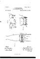
- Figure 1 is a plan view of amachine showing myimprovements.
- Fig. 2 is a perspective view of the machine, looking from the rear.
- Fig. 3 is a perspective View of the upright frame-plate and tray-head plate or frame detached.
- Figs. 4 and 5 are side elevations illustrating the operation of the machine.
- A indicates an upright rectangular plate or frame, which forms the main frame of the machine, upon which the bundle-tray is supported and adjusted, as will appear.
- plates a To the sides of this upright plate or frame are secured plates a, having stud-axles 1) formed upon them, upon which the carrying-wheels B B are journaled. These parts constitute what I term my truck.
- lugs or ears 0 c To the forward face of this upright plate or frame are secured lugs or ears 0 c, to which the rear ends of the thills C O are pivoted. Braces c c extend from the thills in front of the plate A up to near the upper edge of the plate, making the connection of the latter with the thills rigid and supporting the plate in the uprightposition shown.
- lugs or cars cl formed, preferably, on the ends of straps d, secured to the rear face of the frame-plate A, are pivoted near the upper edge or end of the plate A and two near the lower end thereof, similar to the links of a parallel-ruler, and the swinging ends of these links are pivoted in like manner in lugs'f on the ends of straps f on the forward face of an upright frame or plate F, which by the arrangement of links described is adapted to be moved up and down bodily, maintaining its upright position and parallel relation to plate A.
- the plateA has at or near its center a vertical slot 6, and upon one side thereof lugs e e, in bearings in which is journaled a rock-shaft E, having a lever E upon its outer end and upon its inner end ashort arm E which passes through the slot 6, and has its swinging rear end pivoted in a lug or bracket f, fast on the forward face of the frame or plate F.
- the length of arm E corresponds with that of the links D and D, and by operating the lever E the attendant is enabled to raise or lower the frame or plate F, the latter swinging on the parallel links in a manner that will be readily understood.
- a number of rearwardly-projecting parallel rods or fingers F are secured, of suitable size and at a sufficient distance apart to permit the stubble, when the plate and rods are lowered to the position shown in Fig. 5, to readily pass up between the rods, and so to act upon the grain for causing its discharge.
- One side of the platform or tray is left open or without side guard-rods to permit the bundles to be placed on the tray-flooring without obstruction; but the opposite side has one or more guard-rods or fingers F secured to it in a plane above the rods F, and parallel, or substantially so, with the latter, and which serve to uphold in upright position the bundles placed against them; and in about the same plane with or slightly below the guard F are a series of rearwardly-projecting rigid spurs or pointed rods g g, secured to the head plat-e or frame A, upon which the first bundles placed upon the tray are thrust, and which serve to hold in upright position links D D and D D, arranged in pairs, two
- the tray is raised into the position shown in Figs 2 and 4: for receiving the bundles, and is held in that position by any suitable means until the shock is formed, the machine being in the meantime drawn forward over the ground.
- a reaping-machine for taking the bundles therefrom, or at the side of a row of bundles deposited on the ground by said machine, as preferred, and may be, if desired, provided with any suitable arrangement of seatfor the driver; or the latter may walk beside the horse or team, as preferred.
- the combination with the truck-frame and its upright plate or head, of an adjustable tray having a corresponding head-plate, the metal straps secured to the contiguous faces of said head-plates, and the interposed connectinglinks, arranged and adapted to operate 'substantially as described.
- a machine for shocking grain consisting of an upright or head-plate, a series of parallel rods forming the floor of said tray, a series of parallel fingers or spurs projecting in the same direction with said floor-rods, and a side rod or guard, all arranged substantially as and for the purpose described.
Description
(No Model.) 2 SheetsShet 1.
J. BOMGARDNER.
GRAIN SHOCKING MACHINE.
No. 414,282. Patented Nov. 5, 1889.
g jwa 2' Sheets-Sheet 2.
No Model.)
J BOD/[GARDNER GRAIN SHOCKING MAGHINE.
No. 414,282. Patented Nov. 5. 1889L NY PETERS, Wmmfllhogwher, Washington 0 c UNITED STATES PATENT OFFICE.
JOSEPH BOMGARDNER, OF SHANESVILLE, ASSIGNOR TO LEWIS MILLER, 0
, AKRON, OHIO.
GRAIN-SHOCKING MACHINE.
SPECIFICATIONforming part of Letters Patent No. 414,282, dated November 5, 1889.
Application filed September 7, 1888. Serial No. 284,814. (No model.)
To all whom it may concern.-
Be it. known that I, JOSEPH BOMGARDNER, of Shanesville, county of Tuscarawas, and State of Ohio, have invented a new and usefullmprovement in Grain-ShockingMachines, of which the following is a full, clear, and exact description, reference being had to the accompanying drawings, making part of this specification.
My invention relates to a machine having an adjustable tray for receiving and carrying bundles of grain, and upon which they are gathered and arranged in the form of a shock, after which they are deposited and leftstanding in such form on the ground; and it consists in a novel construction of said machine, whereby it is adapted not only to hold the bundles in upright position for forming the shock therein, but whereby the discharge of the completed shock is facilitated; also, to certain details of construction and arrangement of parts of the machine hereinafter described and claimed.
In the accompanying drawings, Figure 1 is a plan view of amachine showing myimprovements. Fig. 2 is a perspective view of the machine, looking from the rear. Fig. 3 is a perspective View of the upright frame-plate and tray-head plate or frame detached. Figs. 4 and 5 are side elevations illustrating the operation of the machine.
A indicates an upright rectangular plate or frame, which forms the main frame of the machine, upon which the bundle-tray is supported and adjusted, as will appear. To the sides of this upright plate or frame are secured plates a, having stud-axles 1) formed upon them, upon which the carrying-wheels B B are journaled. These parts constitute what I term my truck. To the forward face of this upright plate or frame are secured lugs or ears 0 c, to which the rear ends of the thills C O are pivoted. Braces c c extend from the thills in front of the plate A up to near the upper edge of the plate, making the connection of the latter with the thills rigid and supporting the plate in the uprightposition shown.
In suitable lugs or cars cl, formed, preferably, on the ends of straps d, secured to the rear face of the frame-plate A, are pivoted near the upper edge or end of the plate A and two near the lower end thereof, similar to the links of a parallel-ruler, and the swinging ends of these links are pivoted in like manner in lugs'f on the ends of straps f on the forward face of an upright frame or plate F, which by the arrangement of links described is adapted to be moved up and down bodily, maintaining its upright position and parallel relation to plate A.
The plateA has at or near its center a vertical slot 6, and upon one side thereof lugs e e, in bearings in which is journaled a rock-shaft E, having a lever E upon its outer end and upon its inner end ashort arm E which passes through the slot 6, and has its swinging rear end pivoted in a lug or bracket f, fast on the forward face of the frame or plate F. The length of arm E corresponds with that of the links D and D, and by operating the lever E the attendant is enabled to raise or lower the frame or plate F, the latter swinging on the parallel links in a manner that will be readily understood.
To the lower edge or end of the plate or frame F, which forms the head-plate of the tray, a number of rearwardly-projecting parallel rods or fingers F are secured, of suitable size and at a sufficient distance apart to permit the stubble, when the plate and rods are lowered to the position shown in Fig. 5, to readily pass up between the rods, and so to act upon the grain for causing its discharge. One side of the platform or tray is left open or without side guard-rods to permit the bundles to be placed on the tray-flooring without obstruction; but the opposite side has one or more guard-rods or fingers F secured to it in a plane above the rods F, and parallel, or substantially so, with the latter, and which serve to uphold in upright position the bundles placed against them; and in about the same plane with or slightly below the guard F are a series of rearwardly-projecting rigid spurs or pointed rods g g, secured to the head plat-e or frame A, upon which the first bundles placed upon the tray are thrust, and which serve to hold in upright position links D D and D D, arranged in pairs, two
the bundles impaled thereon. These spurs are made shorter than the rods or fingers F and F and serve merely to uphold the bundles placed on the forward end of'the tray or carrier, the bundles subsequently placed upon the tray being upheld by the bundles in front of them and by the guard rod or rods, F
The operation of the machine or bundleshocker described will be readily understood. The tray is raised into the position shown in Figs 2 and 4: for receiving the bundles, and is held in that position by any suitable means until the shock is formed, the machine being in the meantime drawn forward over the ground. at the side of a reaping-machine for taking the bundles therefrom, or at the side of a row of bundles deposited on the ground by said machine, as preferred, and may be, if desired, provided with any suitable arrangement of seatfor the driver; or the latter may walk beside the horse or team, as preferred. An attendant places the bundles upon the tray, the first so placed being thrust against the frame-plate F and upon the spurs g or against the guard F in upright position and resting on their butt-ends, and others in turn against those in front of them until the floor of the't-ray, composed of the rods F',is filled, when others are placed on these, topping out the shock in the usual manner, after which the attendant, by operating the lever E, lowers the tray until the rods F pass down into. the stubble and drag along upon the ground, when the shock will be caught and held by the ground and stubble until the rods F and spurs gare drawn out of and away from it, when the tray is again raised and the operation repeated.
The operation, it will be seen, is very simple, requiring only the raising of the tray, the proper placing of the bundles thereon, and then the lowering of the tray to leave the grain standing in shock form on the ground. Having now described my invention,- I claim as new 1. In a machine for shocking grain, the combination, with the truck-frame, of an adjustable tray provided with an upright headplate and parallel links interposed between andconn ectin g said head-plate and. the truck-. frame, substantially as specified.
2. In a machine for shocking grain, the combination, with the truck-frame and its upright plate or head, of an adjustable tray having a corresponding head-plate, the metal straps secured to the contiguous faces of said head-plates, and the interposed connectinglinks, arranged and adapted to operate 'substantially as described.
3. In a machine for shocking grain, or bundle-carrier consisting of an upright or head-plate, a series of parallel rods forming the floor of said tray, a series of parallel fingers or spurs projecting in the same direction with said floor-rods, and a side rod or guard, all arranged substantially as and for the purpose described.
4. The combination, with the truckframe or plate, of the adjustable tray having the upright head plate or frame, the links con necting said head-plate with the truck-frame and the tray-adj usting lever, substantially as described.
5. The combination, With the upright truck frame or plate, of the upright tray-head plate spurs or fingers rigidly secured to said plate and overhanging the tray-floor for upholding the bundles on said floor, and means, substantially as described, for adjusting said tray for depositing the bundles on the ground.
In testimony whereof I have hereunto set 9 my hand this 8dday of September, A. D. 1888.
JOSEPH BOMGARDNER.
Witnesses:
JOHN C. DONAHEY,
A. D. GRIBBELL.
a tray
Publications (1)
| Publication Number | Publication Date |
|---|---|
| US414282A true US414282A (en) | 1889-11-05 |
Family
ID=2483212
Family Applications (1)
| Application Number | Title | Priority Date | Filing Date |
|---|---|---|---|
| US414282D Expired - Lifetime US414282A (en) | Grain-shocking machine |
Country Status (1)
| Country | Link |
|---|---|
| US (1) | US414282A (en) |
-
0
- US US414282D patent/US414282A/en not_active Expired - Lifetime
Similar Documents
| Publication | Publication Date | Title |
|---|---|---|
| US414282A (en) | Grain-shocking machine | |
| US1905410A (en) | Harvesting machine | |
| US1917352A (en) | Windrowing machine | |
| US1534111A (en) | Harvester and stacker | |
| US842021A (en) | Beet-harvester. | |
| US1026714A (en) | Beet-harvester. | |
| US414776A (en) | Grain-shocking attachment for harvesters | |
| US641288A (en) | Corn-harvester. | |
| US651279A (en) | Corn or cane harvesting machine. | |
| US383317A (en) | Swathing attachment for harvesters | |
| US573895A (en) | Corn-harvester | |
| US512124A (en) | Corn-harvester | |
| US958190A (en) | Grain-shocker. | |
| US231248A (en) | Gleaner and binder | |
| USRE6881E (en) | Improvement in harvesters | |
| US1413966A (en) | christiansen | |
| US325871A (en) | Grain-binding harvester | |
| US588599A (en) | Ezra a | |
| US581219A (en) | mcgormick | |
| US685355A (en) | Clover-buncher. | |
| US341676A (en) | Grain-binding harvester | |
| US351877A (en) | Corn and cane harvester | |
| USRE11065E (en) | Grain-binding harvester | |
| US362930A (en) | buttebfield | |
| US660041A (en) | Shocking attachment for corn-harvesters. |