US4139185A - Lance manipulator - Google Patents
Lance manipulator Download PDFInfo
- Publication number
- US4139185A US4139185A US05/859,586 US85958677A US4139185A US 4139185 A US4139185 A US 4139185A US 85958677 A US85958677 A US 85958677A US 4139185 A US4139185 A US 4139185A
- Authority
- US
- United States
- Prior art keywords
- lance
- melt
- magazine
- manipulator
- frame
- Prior art date
- Legal status (The legal status is an assumption and is not a legal conclusion. Google has not performed a legal analysis and makes no representation as to the accuracy of the status listed.)
- Expired - Lifetime
Links
Images


Classifications
-
- C—CHEMISTRY; METALLURGY
- C21—METALLURGY OF IRON
- C21C—PROCESSING OF PIG-IRON, e.g. REFINING, MANUFACTURE OF WROUGHT-IRON OR STEEL; TREATMENT IN MOLTEN STATE OF FERROUS ALLOYS
- C21C7/00—Treating molten ferrous alloys, e.g. steel, not covered by groups C21C1/00 - C21C5/00
- C21C7/0037—Treating molten ferrous alloys, e.g. steel, not covered by groups C21C1/00 - C21C5/00 by injecting powdered material
-
- C—CHEMISTRY; METALLURGY
- C21—METALLURGY OF IRON
- C21C—PROCESSING OF PIG-IRON, e.g. REFINING, MANUFACTURE OF WROUGHT-IRON OR STEEL; TREATMENT IN MOLTEN STATE OF FERROUS ALLOYS
- C21C5/00—Manufacture of carbon-steel, e.g. plain mild steel, medium carbon steel or cast steel or stainless steel
- C21C5/28—Manufacture of steel in the converter
- C21C5/42—Constructional features of converters
- C21C5/46—Details or accessories
- C21C5/4606—Lances or injectors
- C21C5/462—Means for handling, e.g. adjusting, changing, coupling
Definitions
- the present invention relates to a manipulator for an immersion lance for the injection of finely-divided additive materials into a melt, primarily a metal melt, the manipulator comprising a lance frame on which the lance may be raised and lowered.
- Charging of a melt with additive materials is normally carried out in that the additive material is fed from a storage container through a pneumatic conveyor and a conduit to an immersion lance with a nozzle which discharges within the melt.
- the charging is carried out while the melt is in a ladle to which the melt had previously been transferred from a furnace.
- the available time for treating the melt in the ladle is then restricted, since if it is to be possible to process the melt further, the melt may not cool below a certain temperature.
- an immersion lance By the use of an immersion lance, an effective utilization of the additive material is realized and the treatment can normally be kept to within the restricted treatment time.
- the lance may occasionally break, even though it is normally used only once. In such an event, the break almost always occurs at the surface of the melt so that a portion of the lance sinks to the bottom of the ladle, the stump remaining on the lance frame.
- the lance stump remaining on the lance frame In order, in such an event, that it be possible to carry out the contemplated treatment of the melt within the restricted time available, it is necessary that the lance stump remaining on the lance frame rapidly be replaced with a new, whole lance.
- lance replacement has been carried out for each treatment and has been a circumstantial operation when the ladle is in the operative position.
- the object of the present invention is, therefore, to produce a manipulator which makes possible rapid lance replacement so that the treatment of the melt can be kept to within the restricted treatment time even in the event of lance breakage.
- the manipulator disclosed by way of introduction is provided with a lance magazine with a plurality of pipes, a lance being supported in each one of the pipes, the lance frame of the manipulator being movable between a position above the melt and a lance magazine position, in which latter position a lance in the lance magazine may be directly grasped by the raisable and lowerable holder of the manipulator.
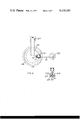
- FIG. 1 is a side elevation of an installation for the injection of additive material into a melt
- FIG. 2 is a schematic plan view of the lance frame
- FIG. 3 is a perspective view of the lance frame and lance magazine.
- FIG. 4 illustrates a detail of the lance magazine.
- the injection installation illustrated in FIG. 1 comprises an additive material container 1 with a conical lower section whose apex has an opening which is in communication by the intermediary of a valve 2 with one end of a supply conduit 3, whose other end is connected to a connection pipe 4 on which a lance 5 is mounted.
- the container 1 is connected, by the intermediary of a valve 6 and a pipe 7 to a storage container 8 for the additive material.
- the container 1 may be placed under pressure, by the intermediary of a conduit 9 connected to a source of gas under pressure (not shown), the conduit discharging in the upper region of the container 1, for forcing out the additive material in the container to the melt.
- the container 1 is connected, by the intermediary of a valve 10 and a conduit 11, to a receptacle 12 which is in communication, by the intermediary of a bellows pipe, with a container 13 which may be identical to the storage container 8.
- the receptacle 12 is in communication with the atmosphere via a filter 14.
- the operation of the installation can be controlled and supervised from an instrument and operating panel 15.
- the function of the above-described section of the installation is as follows.
- additive material can be filled into the container 1 from the storage container 8.
- the added amount of additive material is displayed on the panel 15, load transducers located beneath the legs of the container 1 being utilized.
- the container 1 is placed under pressure via the conduit 9.
- the valve 2 is then opened to a suitable degree and the pressure in the container 1 is regulated accordingly, a selected amount of the additive material can be fed at the desired rate out from the container 1 through the conduit 3, the connection pipe 4 and the lance 5 into the interior of the melt.
- the pressure is lowered in that the valve 10 is opened, the gas under pressure flowing, via the conduit 11 and receptacle 12, out through the filter 14, whereas any possible additive material accompanying the flow is collected in the container 13.
- a conduit 16 connected to the source of gas under pressure, is coupled to the conduit 3 at its connection with the valve 2.
- the lance 5 is carried by a holder 17 which is fixed to a weight 18, the weight being guided by vertical guides on a lance frame 19.
- the weight 18 is suspended from a cable 20 and can, via the cable, be lowered or raised by means of an electric motor 21 controlled from the panel 15.
- the lance frame 19 is rotatably journalled on a swinging wall jib crane 22 and can, by means of an electric motor 23 which is also controlled from the panel 15, be swung to and fro between the position, shown in FIG. 1, above the melt in a ladle 24 and the position, shown in FIG. 2 by means of broken lines, at a lance magazine 25.
- the weight 18 and the lance 5 assume, naturally, the upper position intimated in FIG. 1 by means of dash-dot lines.
- a protective hood 26 with a wicket for the passage of the lance 5 is disposed above the ladle 24.
- the hood 26 is journalled to a frame 27 and may be pivoted, by means of a link 28 and some suitable drive means controlled from the panel 15, between the illustrated horizontal position and a substantially vertical position, in which the ladle 24 is accessible for movement.
- the preferred embodiment of the lance magazine 25, illustrated in FIG. 3, comprises three magazine pipes 29 which are rotatably supported, by means of arms 30 and sleeves 31, on a vertical shaft 32 with a foot 33.
- the pipes 29 are open at their bottom end (where heating can be effected by means of gas) and at their upper end.
- the upper end is slightly flared and supports, as is shown only in FIG. 4, an upright 34 on which an arm 35, with a recess for supporting the lance 5, is journalled so as to be freely pivotal upwardly from a horizontal position in abutment with the upper end of the upright 34.
- the above-described lance manipulator works in the following way.
- the protective hood 26 is first lowered and the lance 5 is then lowered through the wicket in the protective hood 26 down into the melt.
- the previously described injection of additive material can thereafter be commenced. If the lance 5 were to break during this injection process, the injection process is, naturally, discontinued and the remaining stump of the lance 5 is lifted out with the holder 17 by means of the motor 21.
- the lance frame 19 is thereafter swung by means of the motor 23 in a direction towards the lance magazine 25, during which swinging movement the stump of the lance 5 can be disconnected from the connection pipe 4 and from the holder 17 and be released at a suitable point.
- the holder 17 is depressed to its lower position and caused to grasp one of the lances 5 in the magazine 25.
- the connection pipe 4 is coupled to the grasped, new lance 5.
- the holder 17 is then raised, the arm 35 being lifted up by the ceramic casing of the lance 5 until such time as the grasped lance 5 is free from the pipe 29, whereafter the lance frame 19 is swung back to its position above the ladle 24 and the new lance 5 is lowered into the melt.
- the injection of additive material can then be recommenced and concluded.
- the above-described device according to the invention makes possible a rapid lance replacement, this in particular if the holder 17 is controllable from the panel 15 and the coupling between the lance 5 and the connection pipe 4 is a rapid coupling. Since the invention ensures that the restricted time for treatment of the melt in the ladle 24 is not exceeded, it is even possible that each lance 5 could be used several times, until such time as it breaks, instead of being replaced, as is the present situation, for each new melt which is to be treated.
- the lance magazine 25 can be designed in other ways, provided that a new and heated lance 5 in a lance magazine position is always available for transfer to the lance frame 19.
Landscapes
- Chemical & Material Sciences (AREA)
- Engineering & Computer Science (AREA)
- Materials Engineering (AREA)
- Metallurgy (AREA)
- Organic Chemistry (AREA)
- Manufacturing & Machinery (AREA)
- Furnace Charging Or Discharging (AREA)
- Treatment Of Steel In Its Molten State (AREA)
Abstract
Description
Claims (1)
Applications Claiming Priority (2)
| Application Number | Priority Date | Filing Date | Title |
|---|---|---|---|
| SE7614042 | 1976-12-14 | ||
| SE7614042A SE7614042L (en) | 1976-12-14 | 1976-12-14 | LANSMAN OPERATION DEVICE |
Publications (1)
| Publication Number | Publication Date |
|---|---|
| US4139185A true US4139185A (en) | 1979-02-13 |
Family
ID=20329739
Family Applications (1)
| Application Number | Title | Priority Date | Filing Date |
|---|---|---|---|
| US05/859,586 Expired - Lifetime US4139185A (en) | 1976-12-14 | 1977-12-12 | Lance manipulator |
Country Status (5)
| Country | Link |
|---|---|
| US (1) | US4139185A (en) |
| JP (1) | JPS53104506A (en) |
| DE (1) | DE2755738A1 (en) |
| GB (1) | GB1590287A (en) |
| SE (1) | SE7614042L (en) |
Cited By (5)
| Publication number | Priority date | Publication date | Assignee | Title |
|---|---|---|---|---|
| US4278240A (en) * | 1978-08-22 | 1981-07-14 | Asea Aktiebolag | Powder injection apparatus with sieving apparatus |
| US4533125A (en) * | 1982-12-21 | 1985-08-06 | Paul Wurth S.A. | Apparatus for guiding and changing immersion lances |
| US4695042A (en) * | 1985-04-02 | 1987-09-22 | Nippon Steel Corporation | Lance supporting apparatus |
| WO1992013246A1 (en) * | 1991-01-24 | 1992-08-06 | Mount Isa Mines Limited | Lance carriage |
| US20040140597A1 (en) * | 2001-05-26 | 2004-07-22 | Woolley Peter John | Taphole closures |
Families Citing this family (1)
| Publication number | Priority date | Publication date | Assignee | Title |
|---|---|---|---|---|
| EP0189016A1 (en) * | 1984-12-18 | 1986-07-30 | COCKERILL SAMBRE Société Anonyme dite: | Swinging out device for mounting and dismounting a blowing lance |
Citations (3)
| Publication number | Priority date | Publication date | Assignee | Title |
|---|---|---|---|---|
| US51397A (en) * | 1865-12-05 | Improvement in the manufacture of iron and steel | ||
| US3336991A (en) * | 1965-09-27 | 1967-08-22 | Ingersoll Rand Co | Drill rod storage and handling apparatus |
| US3985189A (en) * | 1975-09-19 | 1976-10-12 | Bucyrus-Erie Company | Drill rod handling device |
-
1976
- 1976-12-14 SE SE7614042A patent/SE7614042L/en unknown
-
1977
- 1977-12-02 GB GB50417/77A patent/GB1590287A/en not_active Expired
- 1977-12-12 US US05/859,586 patent/US4139185A/en not_active Expired - Lifetime
- 1977-12-14 DE DE19772755738 patent/DE2755738A1/en not_active Withdrawn
- 1977-12-14 JP JP15040577A patent/JPS53104506A/en active Pending
Patent Citations (3)
| Publication number | Priority date | Publication date | Assignee | Title |
|---|---|---|---|---|
| US51397A (en) * | 1865-12-05 | Improvement in the manufacture of iron and steel | ||
| US3336991A (en) * | 1965-09-27 | 1967-08-22 | Ingersoll Rand Co | Drill rod storage and handling apparatus |
| US3985189A (en) * | 1975-09-19 | 1976-10-12 | Bucyrus-Erie Company | Drill rod handling device |
Cited By (6)
| Publication number | Priority date | Publication date | Assignee | Title |
|---|---|---|---|---|
| US4278240A (en) * | 1978-08-22 | 1981-07-14 | Asea Aktiebolag | Powder injection apparatus with sieving apparatus |
| US4533125A (en) * | 1982-12-21 | 1985-08-06 | Paul Wurth S.A. | Apparatus for guiding and changing immersion lances |
| US4695042A (en) * | 1985-04-02 | 1987-09-22 | Nippon Steel Corporation | Lance supporting apparatus |
| WO1992013246A1 (en) * | 1991-01-24 | 1992-08-06 | Mount Isa Mines Limited | Lance carriage |
| US5374296A (en) * | 1991-01-24 | 1994-12-20 | Mount Isa Mines Limited | Lance carriage |
| US20040140597A1 (en) * | 2001-05-26 | 2004-07-22 | Woolley Peter John | Taphole closures |
Also Published As
| Publication number | Publication date |
|---|---|
| GB1590287A (en) | 1981-05-28 |
| SE7614042L (en) | 1978-06-15 |
| DE2755738A1 (en) | 1978-06-15 |
| JPS53104506A (en) | 1978-09-11 |
Similar Documents
| Publication | Publication Date | Title |
|---|---|---|
| CN108300929B (en) | A method for processing a plate and a feeding mechanism for continuous casting equipment | |
| KR20120132433A (en) | Flexible minimum energy utilization electric arc furnace system and processes for making steel products | |
| US4139185A (en) | Lance manipulator | |
| US4736383A (en) | Method for melting scrap or other materials and apparatus for implementing the method | |
| US2788270A (en) | Method and apparatus for melting metal under vacuum | |
| US2822163A (en) | Charging apparatus | |
| US5390212A (en) | Installation for producing molten metal in an electric furnace | |
| US3013789A (en) | Mobile apparatus for oxygen refining of metal | |
| GB1110961A (en) | Apparatus for casting of molten metal | |
| US4679773A (en) | Horizontal tapping furnace and method of operation | |
| ES8707682A1 (en) | Process and apparatus for charging and discharging a revolving ladle turret in a continuous-casting plant. | |
| HUP0101557A2 (en) | Dosing device for low shaft furnaces | |
| CA1068468A (en) | Continuous casting apparatus with an articulative sealing connection | |
| CN206934945U (en) | Based on the fluid pressure type dust pelletizing system for removing AOD furnace furnace lining | |
| US4244562A (en) | Powder injection apparatus for injection of powder into molten metal | |
| US5263690A (en) | Apparatus for metallurgical treatment of molten steel | |
| US3428301A (en) | Lifting arrangement for a furnace fume elbow and the like | |
| US4328388A (en) | Electro furnace feeding and furnace fume utilization and control | |
| US3022990A (en) | Furnace system | |
| US3093253A (en) | Scrap charging | |
| US2692692A (en) | Foundry equipment | |
| HU210769B (en) | Process for preventing the formation of flue gases in metallurgical processes and during the transport of molten metal from a metallurgical vessel to canting vessels and device for transporting molten metals from a metallurgical furnace to a casting vesse | |
| US3444304A (en) | Making basic oxygen steel in an electric arc furnace system | |
| WO1998006990A1 (en) | Bulk loader | |
| US2704610A (en) | schwengel |
Legal Events
| Date | Code | Title | Description |
|---|---|---|---|
| AS | Assignment |
Owner name: SCANDINAVIAN LANCERS AKTIEBOLAG, SPORTHALLSVAGEN 6 Free format text: ASSIGNMENT OF ASSIGNORS INTEREST.;ASSIGNOR:BRENNER, TOMMY TRUSTEE IN BANKRUPTCY OF KOCKUMS CONSTRUCTION AB;REEL/FRAME:004002/0196 Effective date: 19820304 Owner name: BERGFORSEN, ROGER TRUSTEE IN BANKRUPTCY Free format text: COURT APPOINTMENT;ASSIGNOR:KOCKUMS CONSTRUCTION AKTIEBOLAG BANKRUPT;REEL/FRAME:004002/0197 Effective date: 19810616 Owner name: SCANDINAVIAN LANCERS AKTIEBOLAG, A SWEDISH JOINT S Free format text: ASSIGNMENT OF ASSIGNORS INTEREST;ASSIGNOR:BRENNER, TOMMY TRUSTEE IN BANKRUPTCY OF KOCKUMS CONSTRUCTION AB;REEL/FRAME:004002/0196 Effective date: 19820304 Owner name: BERGFORSEN, ROGER TRUSTEE IN BANKRUPTCY, DISTRICT Free format text: COURT APPOINTMENT;ASSIGNOR:KOCKUMS CONSTRUCTION AKTIEBOLAG BANKRUPT;REEL/FRAME:004002/0197 Effective date: 19810616 |
|
| AS | Assignment |
Owner name: ELKEM A/S, MIDDELTHUNS GATE 27, PO BOX 5430, OSLO Free format text: ASSIGNMENT OF ASSIGNORS INTEREST.;ASSIGNOR:SCANDINAVIAN LANCERS AKTIEBOLAG;REEL/FRAME:004468/0203 Effective date: 19850913 |