US4132946A - Digital readout test probe - Google Patents
Digital readout test probe Download PDFInfo
- Publication number
- US4132946A US4132946A US05/650,331 US65033176A US4132946A US 4132946 A US4132946 A US 4132946A US 65033176 A US65033176 A US 65033176A US 4132946 A US4132946 A US 4132946A
- Authority
- US
- United States
- Prior art keywords
- display
- circuit
- decimal
- converter circuit
- connector
- Prior art date
- Legal status (The legal status is an assumption and is not a legal conclusion. Google has not performed a legal analysis and makes no representation as to the accuracy of the status listed.)
- Expired - Lifetime
Links
- 238000012360 testing method Methods 0.000 title claims abstract description 68
- 239000000523 sample Substances 0.000 title claims abstract description 35
- WABPQHHGFIMREM-UHFFFAOYSA-N lead(0) Chemical compound [Pb] WABPQHHGFIMREM-UHFFFAOYSA-N 0.000 claims abstract description 21
- 239000004020 conductor Substances 0.000 claims abstract description 19
- 230000009977 dual effect Effects 0.000 claims abstract description 11
- 230000008878 coupling Effects 0.000 claims 1
- 238000010168 coupling process Methods 0.000 claims 1
- 238000005859 coupling reaction Methods 0.000 claims 1
- 239000000872 buffer Substances 0.000 description 11
- 238000009413 insulation Methods 0.000 description 6
- 238000010586 diagram Methods 0.000 description 3
- 230000013011 mating Effects 0.000 description 3
- 101150070251 MAN1A1 gene Proteins 0.000 description 1
- 229910000004 White lead Inorganic materials 0.000 description 1
- 239000003990 capacitor Substances 0.000 description 1
- 238000005516 engineering process Methods 0.000 description 1
- 238000003780 insertion Methods 0.000 description 1
- 230000037431 insertion Effects 0.000 description 1
- 239000012212 insulator Substances 0.000 description 1
- 238000000034 method Methods 0.000 description 1
- 238000004377 microelectronic Methods 0.000 description 1
- 230000001105 regulatory effect Effects 0.000 description 1
- 239000004065 semiconductor Substances 0.000 description 1
- 238000013024 troubleshooting Methods 0.000 description 1
Images

Classifications
-
- G—PHYSICS
- G01—MEASURING; TESTING
- G01R—MEASURING ELECTRIC VARIABLES; MEASURING MAGNETIC VARIABLES
- G01R1/00—Details of instruments or arrangements of the types included in groups G01R5/00 - G01R13/00 and G01R31/00
- G01R1/02—General constructional details
- G01R1/04—Housings; Supporting members; Arrangements of terminals
- G01R1/0408—Test fixtures or contact fields; Connectors or connecting adaptors; Test clips; Test sockets
- G01R1/0425—Test clips, e.g. for IC's
-
- G—PHYSICS
- G01—MEASURING; TESTING
- G01R—MEASURING ELECTRIC VARIABLES; MEASURING MAGNETIC VARIABLES
- G01R31/00—Arrangements for testing electric properties; Arrangements for locating electric faults; Arrangements for electrical testing characterised by what is being tested not provided for elsewhere
- G01R31/28—Testing of electronic circuits, e.g. by signal tracer
- G01R31/317—Testing of digital circuits
- G01R31/3181—Functional testing
- G01R31/319—Tester hardware, i.e. output processing circuits
- G01R31/3193—Tester hardware, i.e. output processing circuits with comparison between actual response and known fault free response
-
- Y—GENERAL TAGGING OF NEW TECHNOLOGICAL DEVELOPMENTS; GENERAL TAGGING OF CROSS-SECTIONAL TECHNOLOGIES SPANNING OVER SEVERAL SECTIONS OF THE IPC; TECHNICAL SUBJECTS COVERED BY FORMER USPC CROSS-REFERENCE ART COLLECTIONS [XRACs] AND DIGESTS
- Y10—TECHNICAL SUBJECTS COVERED BY FORMER USPC
- Y10S—TECHNICAL SUBJECTS COVERED BY FORMER USPC CROSS-REFERENCE ART COLLECTIONS [XRACs] AND DIGESTS
- Y10S439/00—Electrical connectors
- Y10S439/912—Electrical connectors with testing means
Definitions
- This invention pertains to test equipment for electronic circuits and is particularly concerned with a novel digital readout test probe which is especially useful in providing a decimal readout of a binary coded decimal signal appearing at selected terminal pins of an integrated circuit.
- test equipment for such digital circuitry provide maximum utility and convenience to the person using the equipment. Because present digital circuit technology operates with binary type logic signals, testing of other than the simplest circuit can be a time consuming procedure. Moreover, with the miniaturized microcircuitry, the task of physically making an electrical connection with a desired test point on the circuit can be difficult.
- the present invention is directed to a novel and extremely useful digital readout test probe for use by electronic technicians and engineers in designing developing, testing and/or repairing systems incorporating digital circuits.
- One feature of the present invention is that it is directly compatible with various types of microcircuits including DTL, TTL, and CMOS type systems.
- the probe contains its own power supply and possesses extremely high input impedance, and thus, cannot load down the digital circuits under test.
- the probe can accept input signals over the voltage ranges customarily prevailing in present digital circuits.
- Another feature of the invention is that it provides a digital decimal display representative of a binary coded decimal signal present in the circuit under test. This is important in that information as to the performance of the digital circuitry under test is readily displayed in an intelligible form to the user of the probe.
- a further feature of the invention is that the probe can be programmed to monitor data for any possible pin configuration in an integrated circuit under test. Connection to the circuit under test is via a clip-on type connector which is coupled via color coded lead wires to a converter circuit which drives the decimal readout display.
- the lead wires terminate in hollow terminal connector pins which may be mated with selected conductor pins on the connector in accordance with the pin configuration of the integrated circuit under test. This is important in providing maximum versatility and operator convenience so that even in complicated digital circuits containing numerous different types of integrated circuit devices, testing can be accomplished with a single piece of equipment which is readily programmed according to each specific device under test.
- Ancillary features of the present invention include its compact size permitting portability and use in close quarters; a self-test feature for testing the operability of the probe circuitry and display; and color coding for each lead wire according to the significance of the digital signal conducted thereby.
- FIG. 1 is a perspective view illustrating a first embodiment of digital readout test probe embodying principles of the present invention.
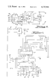
- FIG. 2 is an electronic schematic diagram of circuitry contained in the probe of FIG. 1.
- FIG. 3 is a front view of a second embodiment of probe embodying principles of the present invention.
- FIG. 4 is an electronic schematic diagram of electronic circuitry contained in the probe of FIG. 3.
- the first embodiment of probe 10 according to the present invention shown in FIGS. 1 and 2 comprises a housing 12, a power supply 14 and a connector 16.
- Housing 12 contains a digital readout display 18 which can display each of the ten decimal digits 0 through 9, one at a time.
- an electronic converter circuit 20 which converts digital information from the circuit under test to drive display 18.
- a pair of connector plugs 22 and 24 project from housing 12 for insertion into mating receptacles 26 and 28 on power supply 14.
- Power supply 14 is entirely conventional and develops a regulated DC voltage of appropriate potential between receptacles 26 and 28 which is supplied via terminals 22 and 24, when engaged therewith, to drive display 18 and converter circuit 20.
- Power supply 14 further includes a conventional wall plug 30 which may be plugged into a conventional service receptacle (for example 115 VAC, 60 hz) to energize the power supply.
- An on-off switch 32 controls the availability of DC power at receptacles 26 and 28 to thereby turn the probe on and off.
- Connector 16 is electrically connected with the converter circuit 20 inside housing 12 by means of a plurality of individual lead wires of appropriate length. In the illustrated embodiment five lead wires 34, 36, 38, 40 and 42 are utilized.
- the lead wires may be contained within a suitable sheath 44 for most of their length from housing 12. In order to facilitate the identification of the lead wires, they are preferably uniquely coded, for example, by unique color coded insulation on each lead wire.
- lead wire 34 may be coded with black insulation, lead wire 36 with brown insulation, lead wire 38 with red insulation, lead wire 40 with yellow insulation and lead wire 42 with white insulation.
- Each of the lead wires 34, 36, 38, 40 and 42 terminates in a hollow push-on type terminal pin, 34a, 36a, 38a, 40a, and 42a, which may be covered by a tubular insulator sleeve.
- the terminal pins 34a, 36a, 38a, 40a and 42a are identical and each may be manually engaged with and disengaged from the free end of any one of the conductor elements 46 of connector 16.
- Connector 16 is a conventional dual in-line pin clip-type connector for making connection with each of the terminal pins of a conventional dual in-line pin type integrated circuit device 48.
- the illustrated clip is for a sixteen pin configuration having two rows of eight conductors 46.
- the signal appearing at each of the terminal pins of the integrated circuit is also conducted via the corresponding conductor 46 which is in contact therewith.
- the probe is connected with the desired terminal pins on integrated circuit 48 to monitor the signals appearing at those terminal pins.
- Converter circuit 20 is adapted to convert a binary coded decimal signal into an appropriate signal for driving display 18 whereby the decimal number appearing on display 18 is representative of the decimal value of the binary coded decimal signal. Accordingly, there are four input circuits to converter circuit 20, one for each binary digit of the binary coded decimal signal.
- the most significant binary digit of the binary coded decimal signal is conducted via lead wire 42 to the most significant bit input of converter circuit 20; the next most significant via lead wire 40 to the next most significant bit input; the next most significant via lead wire 38 to the next most significant bit input; and the least significant via lead wire 36 to the least significant bit input.
- a common return path is provided via lead wire 34.
- Converter circuit 20 comprises in detail a buffer section 50 and a decoder section 52.
- Buffer section 50 comprises four individual buffers 50a, 50b, 50c, and 50d, each of which has its input connected to a corresponding one of the lead wires 36, 38, 40 and 42.
- An input impedance resistor is connected between the input of each buffer and the return line 34, the latter also connecting with each individual buffer.
- the resistors are designated 52a, 52b, 52c, and 52d.
- the outputs of the four buffers 50a, 50b, 50c, and 50d are connected with corresponding inputs of decoder 52. In turn the outputs of decoder 52 are coupled with appropriate inputs of display 18.
- buffer section 50, decoder section 52 and display 18 are energized from the DC voltage supplied by power supply 14 across the terminals 22 and 24.
- the input impedance resistors 52a, 52b, 52c and 52d in conjunction with the individual buffers 50a, 50b, 50c and 50d present an extremely high input impedance to the signals supplied from the integrated circuit via connector 16 and lead wires 36, 38, 40, and 42 so that the probe operates for all practical purposes with zero power draw from the integrated circuit and all power supplied from power supply 14.
- buffer section 50 may comprise an RCA CD 4050 integrated circuit device, decoder section 52 a Motorola MC 7447 integrated circuit device, and display 18 a Monsanto numerical display MAN1A. It will be observed that display 18 comprises a plurality of seven individual energizable segments which in toto form the numeral eight.
- these individual elements are selectively energizable by decoder 52 in accordance with the binary coded decimal signal input to buffer section 50, so that one of the ten decimal digits zero through nine will be displayed on the display in accordance with the value of the binary coded decimal signal appearing at the selected test points of the integrated circuit under test.
- the entire probe thus provides an extremely useful, versatile device and it possesses a compact size which is desirable for test equipment.
- FIGS. 3 and 4 illustrate a second embodiment of probe 54 according to principles of the present invention.
- Probe 54 comprises a somewhat larger housing 56 than in the first embodiment and this larger housing contains a legend thereon showing both input and output codes.
- the larger housing 56 contains the DC power supply for the display and converter circuitry with the cord and plug 30 emanating from the housing.
- the second embodiment also differs from the first embodiment in that the lead wires 34, 36, 38, 40 and 42 terminate at the housing in a connector plug 58 which plugs into and is keyed with a mating receptacle mounted in the side wall of housing 56.
- connector plug 58 and the mating receptacle on housing 56 enables the connector 16 and lead wire bundle to be disconnected from housing 56; however, the lead wires at their opposite ends still terminate in the hollow terminal pins 34a, 36a, 38a, 40a, and 42a for programmable connection with the conductor pins 46 on connector 16.
- the input code legend relates the color coded lead wires with the significance of the binary digits which are to be monitored in the integrated circuit under test.
- the brown lead wire 36 represents the 2 0 binary digit
- the red lead wire 38 the 2 1 binary digit
- the yellow lead wire 40 the 2 2 binary digit
- the white lead wire 42 the 2 3 binary digit.
- Many present integrated circuit terminal pin designations assign the numeral 1 or the letter A to the 2 0 binary digit, the numeral 2 or the letter B to the 2 1 binary digit, the numeral 3 or the letter C to the 2 2 binary digit, and the numeral 4 or the letter D to the 2 3 binary digit.
- the provision of the input code legend on the face of the housing serves as a convenient reminder to the user.
- the output code legend relates the character appearing on display 18 with the decimal number.
- the character displayed on display 18 is the decimal number.
- the converter circuit and display are capable of generating on the display characters representative of such erroneous binary coded decimal numbers.
- the output code illustrates these characters for the binary coded decimal equivalents of the decimal numbers ten through fourteen and for the binary coded decimal representation of the decimal number fifteen, the display is blank.
- FIG. 4 illustrates an electronic schematic diagram of the probe circuitry which has several differences from that of probe 10.
- the circuit of FIG. 4 comprises for buffer section 50, a Motorola integrated circuit device MC14050CP; for the decoder section 52 and display 18, a Monsanto device MDA1601.
- FIG. 4 illustrates the specific connection of the devices in circuit with the reference numerals and characters on each device corresponding to the manufacturers termial designations.
- a self-test feature is provided by means of a push-to-test switch 60 which is located on the front face of housing 56. Switch 60 is electrically connected in circuit as illustrated in FIG. 4 so that upon actuation of switch 60, a ground signal is applied to decoder section 52 which, if the decoder and display are operating properly, causes all seven segments of display 18 to be energized.
- FIG. 4 also shows the power supply circuit for developing the appropriate DC voltage for the converter and display.
- This power supply circuit has an input which receives the usual AC power through a fuse 62 and the power on-off control switch 32.
- An AC to DC converter device 64 by way of example, a National Semiconductor model number P741-5005S, whose output is paralleled by a capacitor 66, is utilized to develop the DC potential, which is illustratively +5 volts.
Landscapes
- Physics & Mathematics (AREA)
- General Physics & Mathematics (AREA)
- Engineering & Computer Science (AREA)
- General Engineering & Computer Science (AREA)
- Tests Of Electronic Circuits (AREA)
- Measuring Leads Or Probes (AREA)
Abstract
Description
Claims (7)
Priority Applications (1)
| Application Number | Priority Date | Filing Date | Title |
|---|---|---|---|
| US05/650,331 US4132946A (en) | 1976-01-19 | 1976-01-19 | Digital readout test probe |
Applications Claiming Priority (1)
| Application Number | Priority Date | Filing Date | Title |
|---|---|---|---|
| US05/650,331 US4132946A (en) | 1976-01-19 | 1976-01-19 | Digital readout test probe |
Publications (1)
| Publication Number | Publication Date |
|---|---|
| US4132946A true US4132946A (en) | 1979-01-02 |
Family
ID=24608452
Family Applications (1)
| Application Number | Title | Priority Date | Filing Date |
|---|---|---|---|
| US05/650,331 Expired - Lifetime US4132946A (en) | 1976-01-19 | 1976-01-19 | Digital readout test probe |
Country Status (1)
| Country | Link |
|---|---|
| US (1) | US4132946A (en) |
Cited By (13)
| Publication number | Priority date | Publication date | Assignee | Title |
|---|---|---|---|---|
| US4646002A (en) * | 1984-05-10 | 1987-02-24 | Regents Of The University Of Minnesota | Circuit for high impedance broad band probe |
| US4749362A (en) * | 1980-11-24 | 1988-06-07 | The Johns Hopkins University | Short-circuit-proof connector clip for a multiterminal circuit |
| US4835469A (en) * | 1987-07-24 | 1989-05-30 | John Fluke Mfg. Co., Inc. | Integrated circuit clip for circuit analyzer |
| US4947115A (en) * | 1988-06-06 | 1990-08-07 | The Siemon Company | Test probe adapter |
| US4963821A (en) * | 1989-04-14 | 1990-10-16 | Tektronix, Inc. | Probe and method for testing a populated circuit board |
| US5130648A (en) * | 1988-09-12 | 1992-07-14 | Kjell Moum | Instrument for checking the operational state of an ic-circuit |
| US6276956B1 (en) * | 1999-04-12 | 2001-08-21 | Sencore, Inc. | Dual point test probe for surface mount type circuit board connections |
| US20040135587A1 (en) * | 2003-01-15 | 2004-07-15 | Ort Gene P. | Color code and alphanumeric system for identifying components of a proximity measurement system |
| US20040189336A1 (en) * | 2003-03-26 | 2004-09-30 | Tokyo Electron Limited | Apparatus for monitoring the connection state of connectors and a method for using the same |
| US6822463B1 (en) | 2001-12-21 | 2004-11-23 | Lecroy Corporation | Active differential test probe with a transmission line input structure |
| US9517338B1 (en) | 2016-01-19 | 2016-12-13 | Axonics Modulation Technologies, Inc. | Multichannel clip device and methods of use |
| US10195423B2 (en) | 2016-01-19 | 2019-02-05 | Axonics Modulation Technologies, Inc. | Multichannel clip device and methods of use |
| CN113640735A (en) * | 2021-09-07 | 2021-11-12 | 浙江晨泰科技股份有限公司 | Smart electric meter calibration equipment |
Citations (10)
| Publication number | Priority date | Publication date | Assignee | Title |
|---|---|---|---|---|
| US2945204A (en) * | 1957-06-05 | 1960-07-12 | Western Electric Co | Designation strips for apparatus |
| US3094212A (en) * | 1961-12-14 | 1963-06-18 | Gen Precision Inc | Automatic component tester |
| US3268888A (en) * | 1963-03-22 | 1966-08-23 | Anker Werke Ag | Electromechanical apparatus for converting coded into decoded digital values |
| US3577141A (en) * | 1968-11-14 | 1971-05-04 | United Merchants & Mfg | Binary to decimal tree relay decoder circuit with memory display |
| US3728530A (en) * | 1972-03-13 | 1973-04-17 | Motorola Inc | Binary to decimal converter circuit |
| US3750015A (en) * | 1970-11-12 | 1973-07-31 | Comtec Ind Inc | Digital logic test probe for indicating both signal levels as well as a count of changes in signal levels |
| US3831149A (en) * | 1973-02-14 | 1974-08-20 | Burroughs Corp | Data monitoring apparatus including a plurality of presettable control elements for monitoring preselected signal combinations and other conditions |
| US3870953A (en) * | 1972-08-01 | 1975-03-11 | Roger Boatman & Associates Inc | In circuit electronic component tester |
| US3893028A (en) * | 1973-10-16 | 1975-07-01 | Hewlett Packard Co | Probe multimeter with display inverting means |
| US3899239A (en) * | 1974-06-24 | 1975-08-12 | Us Navy | Integrated circuit test clamp |
-
1976
- 1976-01-19 US US05/650,331 patent/US4132946A/en not_active Expired - Lifetime
Patent Citations (10)
| Publication number | Priority date | Publication date | Assignee | Title |
|---|---|---|---|---|
| US2945204A (en) * | 1957-06-05 | 1960-07-12 | Western Electric Co | Designation strips for apparatus |
| US3094212A (en) * | 1961-12-14 | 1963-06-18 | Gen Precision Inc | Automatic component tester |
| US3268888A (en) * | 1963-03-22 | 1966-08-23 | Anker Werke Ag | Electromechanical apparatus for converting coded into decoded digital values |
| US3577141A (en) * | 1968-11-14 | 1971-05-04 | United Merchants & Mfg | Binary to decimal tree relay decoder circuit with memory display |
| US3750015A (en) * | 1970-11-12 | 1973-07-31 | Comtec Ind Inc | Digital logic test probe for indicating both signal levels as well as a count of changes in signal levels |
| US3728530A (en) * | 1972-03-13 | 1973-04-17 | Motorola Inc | Binary to decimal converter circuit |
| US3870953A (en) * | 1972-08-01 | 1975-03-11 | Roger Boatman & Associates Inc | In circuit electronic component tester |
| US3831149A (en) * | 1973-02-14 | 1974-08-20 | Burroughs Corp | Data monitoring apparatus including a plurality of presettable control elements for monitoring preselected signal combinations and other conditions |
| US3893028A (en) * | 1973-10-16 | 1975-07-01 | Hewlett Packard Co | Probe multimeter with display inverting means |
| US3899239A (en) * | 1974-06-24 | 1975-08-12 | Us Navy | Integrated circuit test clamp |
Cited By (16)
| Publication number | Priority date | Publication date | Assignee | Title |
|---|---|---|---|---|
| US4749362A (en) * | 1980-11-24 | 1988-06-07 | The Johns Hopkins University | Short-circuit-proof connector clip for a multiterminal circuit |
| US4646002A (en) * | 1984-05-10 | 1987-02-24 | Regents Of The University Of Minnesota | Circuit for high impedance broad band probe |
| US4835469A (en) * | 1987-07-24 | 1989-05-30 | John Fluke Mfg. Co., Inc. | Integrated circuit clip for circuit analyzer |
| US4947115A (en) * | 1988-06-06 | 1990-08-07 | The Siemon Company | Test probe adapter |
| US5130648A (en) * | 1988-09-12 | 1992-07-14 | Kjell Moum | Instrument for checking the operational state of an ic-circuit |
| US4963821A (en) * | 1989-04-14 | 1990-10-16 | Tektronix, Inc. | Probe and method for testing a populated circuit board |
| US6276956B1 (en) * | 1999-04-12 | 2001-08-21 | Sencore, Inc. | Dual point test probe for surface mount type circuit board connections |
| US7019544B1 (en) | 2001-12-21 | 2006-03-28 | Lecroy Corporation | Transmission line input structure test probe |
| US6822463B1 (en) | 2001-12-21 | 2004-11-23 | Lecroy Corporation | Active differential test probe with a transmission line input structure |
| US20040135587A1 (en) * | 2003-01-15 | 2004-07-15 | Ort Gene P. | Color code and alphanumeric system for identifying components of a proximity measurement system |
| US6879144B2 (en) * | 2003-01-15 | 2005-04-12 | Gene P. Ort | Color code alphanumeric system for identifying components of a proximity measurement system |
| US20040189336A1 (en) * | 2003-03-26 | 2004-09-30 | Tokyo Electron Limited | Apparatus for monitoring the connection state of connectors and a method for using the same |
| US9517338B1 (en) | 2016-01-19 | 2016-12-13 | Axonics Modulation Technologies, Inc. | Multichannel clip device and methods of use |
| US10195423B2 (en) | 2016-01-19 | 2019-02-05 | Axonics Modulation Technologies, Inc. | Multichannel clip device and methods of use |
| CN113640735A (en) * | 2021-09-07 | 2021-11-12 | 浙江晨泰科技股份有限公司 | Smart electric meter calibration equipment |
| CN113640735B (en) * | 2021-09-07 | 2024-02-06 | 浙江晨泰科技股份有限公司 | Smart electric meter verifying attachment |
Similar Documents
| Publication | Publication Date | Title |
|---|---|---|
| US4132946A (en) | Digital readout test probe | |
| US5285163A (en) | Electrical cable continuity and voltage tester | |
| US5272438A (en) | Field test unit for circuit breaker | |
| US4525802A (en) | Portable electronic testing apparatus | |
| EP0201181A1 (en) | Probe assembly for use with electronic instrument | |
| US4218745A (en) | Microcomputer assisted electrical harness fabrication and testing system | |
| US7259567B2 (en) | Power tester for electrical outlets | |
| US4837488A (en) | Portable identifier and tester units for computer communication cables | |
| US4257002A (en) | Automatic harness tester | |
| US3315163A (en) | Meter probe with slidable circuit changing contact point | |
| US4399400A (en) | Apparatus for testing multiconductor cables and having transition circuit means for extending its capability | |
| US4564728A (en) | Apparatus for testing a telephone line | |
| US4114091A (en) | Apparatus for matching wires in multiple wire conductors and attendant method | |
| US4827498A (en) | Telephone line and instrument tester | |
| US4385272A (en) | Cable checker utilizing logic circuitry | |
| US5838559A (en) | Host electronic equipment with internal power supply adapted for supplying power directly to peripherals | |
| US5686840A (en) | Method and apparatus for throttle position sensor testing | |
| US4550287A (en) | Data bus test instrument having a tri-colored LED and indicating continuity, voltage and polarity | |
| KR900003233B1 (en) | Automatic electrical connection for fast and instantaneous power supply to electronic circuits | |
| US7591670B2 (en) | Connector device having counter thereof | |
| US2994819A (en) | Electrical power tool tester | |
| US7126325B2 (en) | Digital multi-meter with operational error prevention technology using LED and microprocessor with input sockets | |
| US4701696A (en) | Retargetable buffer probe | |
| US3922507A (en) | Distributing terminal assembly test apparatus | |
| US4258251A (en) | Apparatus for use in ordering trials |
Legal Events
| Date | Code | Title | Description |
|---|---|---|---|
| AS | Assignment |
Owner name: FIDELITY UNION TRUST COMPANY, 765 BROAD ST., NEWAR Free format text: MORTGAGE;ASSIGNOR:CHRYSLER CORPORATION;REEL/FRAME:003832/0358 Effective date: 19810209 Owner name: FIDELITY UNION TRUST COMPANY, TRUSTEE,NEW JERSEY Free format text: MORTGAGE;ASSIGNOR:CHRYSLER CORPORATION;REEL/FRAME:003832/0358 Effective date: 19810209 |
|
| AS | Assignment |
Owner name: CHRYSLER CORPORATION, HIGHLAND PARK, MI 12000 LYNN Free format text: ASSIGNORS HEREBY REASSIGN, TRANSFER AND RELINQUISH THEIR ENTIRE INTEREST UNDER SAID INVENTIONS AND RELEASE THEIR SECURITY INTEREST.;ASSIGNORS:FIDELITY UNION BANK;ARNEBECK, WILLIAM, INDIVIDUAL TRUSTEE;REEL/FRAME:004063/0604 Effective date: 19820217 |
|
| AS | Assignment |
Owner name: CHRYSLER CORPORATION Free format text: PARTES REASSIGN, TRANSFER AND RELINQUISH THEIR ENTIRE INTEREST UNDER SAID PATENTS ALSO RELEASE THEIR SECURITY INTEREST.;ASSIGNOR:MANUFACTURERS NATIONAL BANK OF DETROIL (CORPORATE TRUSTEE) AND BLACK DONALD E., (INDIVIDUAL TRUSTEE);REEL/FRAME:004355/0154 Effective date: 19840905 |