US4124194A - Metallic seat construction for valves - Google Patents
Metallic seat construction for valves Download PDFInfo
- Publication number
- US4124194A US4124194A US05/807,852 US80785277A US4124194A US 4124194 A US4124194 A US 4124194A US 80785277 A US80785277 A US 80785277A US 4124194 A US4124194 A US 4124194A
- Authority
- US
- United States
- Prior art keywords
- seat
- annular
- valve
- lip
- gate
- Prior art date
- Legal status (The legal status is an assumption and is not a legal conclusion. Google has not performed a legal analysis and makes no representation as to the accuracy of the status listed.)
- Expired - Lifetime
Links
Images
Classifications
-
- F—MECHANICAL ENGINEERING; LIGHTING; HEATING; WEAPONS; BLASTING
- F16—ENGINEERING ELEMENTS AND UNITS; GENERAL MEASURES FOR PRODUCING AND MAINTAINING EFFECTIVE FUNCTIONING OF MACHINES OR INSTALLATIONS; THERMAL INSULATION IN GENERAL
- F16K—VALVES; TAPS; COCKS; ACTUATING-FLOATS; DEVICES FOR VENTING OR AERATING
- F16K3/00—Gate valves or sliding valves, i.e. cut-off apparatus with closing members having a sliding movement along the seat for opening and closing
- F16K3/02—Gate valves or sliding valves, i.e. cut-off apparatus with closing members having a sliding movement along the seat for opening and closing with flat sealing faces; Packings therefor
- F16K3/16—Gate valves or sliding valves, i.e. cut-off apparatus with closing members having a sliding movement along the seat for opening and closing with flat sealing faces; Packings therefor with special arrangements for separating the sealing faces or for pressing them together
- F16K3/18—Gate valves or sliding valves, i.e. cut-off apparatus with closing members having a sliding movement along the seat for opening and closing with flat sealing faces; Packings therefor with special arrangements for separating the sealing faces or for pressing them together by movement of the closure members
- F16K3/184—Gate valves or sliding valves, i.e. cut-off apparatus with closing members having a sliding movement along the seat for opening and closing with flat sealing faces; Packings therefor with special arrangements for separating the sealing faces or for pressing them together by movement of the closure members by means of cams
- F16K3/186—Gate valves or sliding valves, i.e. cut-off apparatus with closing members having a sliding movement along the seat for opening and closing with flat sealing faces; Packings therefor with special arrangements for separating the sealing faces or for pressing them together by movement of the closure members by means of cams by means of cams of wedge from
Definitions
- This invention is related to metallic seats for valves. More specifically this invention is related to completely metal seat assemblies for gate valves wherein the seat is constructed for use in a high temperature service and where the seat provides a primary sealing element for low pressures and a secondary seating element for higher pressures.
- the metallic valve seat constructions shown in these patents are generally complicated structures which must be welded to or otherwise fixed to the valve body and which provide only a principle sealing element or surface to contact the gate member.
- each of these seat constructions only one seal element is provided to contact the gate member; however, they do not provide supporting structure of sufficient strength to seal against and support an expanding or wedging gate member nor do they provide the combination of a positive primary and secondary seal.
- the valve seat assembly of this invention includes an annular seat support member which is rigidly mounted in a seat pocket of a gate valve.
- the seat pockets in this valve open to the valve chamber and to the flow passageways.
- An annular seat member is axially movably mounted in the seat support member by an annular flexible and radially disposed member which functions as a spring to urge the seat member outward to engage the gate member and which functions as a seal between the seat member and the seat support member.
- the seat member is provided with an annular planar sealing face and a cantilever seal member extending from a groove around the annular planar sealing face. The free end of the cantilever seal member extends beyond the planar sealing face for contact with the gate member.
- One object of this invention is to provide an all metal gate valve seat structure overcoming the aforementioned disadvantages of the prior art devices.
- one other object of this invention is to provide a metal seat structure for a gate valve which has an axially movable seat member that is urged toward the gate member by a metallic spring with the seat having a deformable face seal element functioning as a primary seal and extending beyond the planar sealing face of the seat member.
- Another object of this invention is to provide an all metal gate valve seal assembly which can be pressed into the seat pocket of a gate valve that has a laterally expandable gate assembly to seal when the gate assembly is in a collapsed condition as well as in an expanded condition.
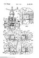
- FIG. 1 is a cross-sectional elevation view of a gate valve having an expanding gate assembly and employing the seat construction of this invention with the valve shown in the closed position and the gate assembly in a collapsed condition;
- FIG. 2 is an enlarged cross-sectional fragmental view of a portion of the gate valve body, the gate, and the seat assembly of this invention taken with the valve in the position as shown in FIG. 1;
- FIG. 3 is an enlarged fragmental view of a portion of the gate and both seats from the valve shown in FIG. 1, with the gate assembly shown in the closed position, centered between the seats, and collapsed;
- FIG. 4 is an enlarged fragmental view similar to FIG. 3 and with the gate assembly in the expanded condition and in the open position.
- FIG. 1 shows a gate valve employing the novel metal seat structure of this invention.
- the gate valve includes a valve body 10 having a valve chamber 12 therein with flow passageways 14 and 16 through the valve body communicating with the valve chamber.
- An expanding parallel sided type gate assembly indicated generally at 18 is mounted in the valve chamber between flow passageways 14 and 16.
- a pair of seat assemblies 20 and 22 are mounted around the respective flow passageways 14 and 16 and reside in contact with gate assembly 18.
- a valve stem 24 is secured on to the upper end of gate assembly 18 and extends through a valve bonnet 26 which is mounted on valve body 10.
- An operator in the form of a handwheel 28 is shown on the upper end of valve stem 24 for moving the gate assembly between open and closed positions.
- Gate assembly 18 includes a gate member 30 and a segment 32 which move together as a unit and expand laterally in the open and closed positions to insure positive engagement with the valve seats for fluid-tight sealing in the open and closed positions.
- Gate 30 has a flat sealing surface 34 on the side which contacts seat assembly 20, a notch 36 transversely across the opposite side thereof, and an opening 38 through the lower end of the member.
- Stem 24 is secured to the upper end of gate 30.
- Segment 32 has a flat sealing surface 40 on one side which contacts seat assembly 22, an inclined surface 42 extending outwardly and transverse to the segment on the opposite side to engage gate notch 36.
- An opening 44 through the lower end of segment 32 aligns with the gate opening 38 when gate assembly 18 is in the open position.
- sealing surfaces 34 and 40 are substantially parallel when gate assembly 18 is expanded in both the open and closed positions and these sealing surfaces are more or less parallel when gate assembly 18 is in the collapsed position as shown in FIG. 1.
- Movement of gate assembly 18 to either the closed or the open position brings segment 32 into contact with lower or upper stops inside the valve body so continued displacement of gate 30 wedges gate assembly 18 between the seat members because of the sliding of gate 30 relative to segment 32.
- the upper stop is the inside surface of the valve body bonnet outward of the stem and stem-gate coupler passageway.
- the lower stop is a protrusion in the bottom of the valve chamber.
- the seat pocket or recess for the seat assembly 22 includes an annular wall 48 which is coaxial with fluid passageway 16 and joins a radially disposed seat pocket and wall 50 on one end and the valve chamber on the opposite end thereof. Radially disposed wall 50 is substantially perpendicular to flow passageway 16.
- Seat assembly 22 comprises a seat support member 52 which is joined by a flexible member 54 to a seat member 56.
- Seat support member 52 is an annular member having a generally cross-section "L" shape and receiving the seat member 56 in the interior thereof.
- Seat support member 52 has one leg defining a generally cylindrical outer wall 58 which is substantially perpendicular to the other leg defining a radially disposed end wall 60.
- Seat support member outer wall 58 rests in flush contact with seat pocket outer wall 48 in an interference fit so the seat assembly is retained in the valve body.
- the interior of seat support member 52 includes a cross-sectionally round interior wall 62 extending from the open end of the member to a radially disposed inner wall at the interior of the radially disposed portion. This radially disposed inner wall terminates at an opening 64 which is substantially aligned with fluid passageway 16.
- the seat support member inner wall is provided with a recess or cutaway portion 66 through a mid-portion thereof to receive a flexible member 54.
- Seat member 56 is an annular member having the interior opening 68 generally aligning with the flow passageway 16, and including a generally cylindrical outer surface 70, a substantially planar sealing surface 72 adjacent to gate assembly 18, and a rear wall 74 on the side opposite to the sealing face.
- Seat member 56 also has a lip seal member 76 extending from an annular groove 78 around a mid-portion of sealing face 72. Lip seal member 76 extends outwardly in a generally frusto-conical shape from the bottom portion of the groove 78 and terminates at a tip 80 which extends beyond sealing face 72 when lip seal member 76 is in a free position. Lip seal member 76 is substantially wider at the root portion which is in the bottom of groove 78 than at tip 80.
- Tip 80 is smaller in radial diameter than the root portion of seal member 76.
- Perferably lip seal member 76 is positioned around a radially inner portion of sealing face 72.
- Groove 78 is sufficiently wide to permit deflection of lip seal member 76 completely into groove 78 when seat sealing face 72 is in flush contact with the gate assembly sealing surface. In this completely deflected position no portion of lip seal member 76 contacts the side of groove 78.
- Seat member cylindrical outer surface 70 is spaced slightly from seat support member annular inner wall 62 so that seat member 56 can move longitudinally within seat support member 52. This spacing must necessarily be sufficient to permit movement of seat member 56 at room temperature and at an extremely elevated temperature such as above 1,000° F. or at a substantially reduced temperature such as -50° F.
- Seat member rear wall 74 is provided with a longitudinally extending peripheral ridge 82 around the outer peripheral portion thereof. Ridge 82 serves as an attachment point for flexible member 54 and a stop to contact seat support member 52.
- Flexible member 54 is a combination spring and seal member connecting seat support member 52 and seat member 56 to provide a seal between the two members and a spring action to urge seat member 56 outward to contact gate assembly 18.
- Flexible member 54 has a radially inner portion 84 which is secured to seat support member 52 by an annular weld 86 around the opening of the seat support member.
- the radially outer portion 88 of flexible member 54 is secured to seat member ridge 82 by an annular weld 90. Welds 86 and 90 secure flexible member 54 and provide for fluid-tight sealing between seat support member 52 and seat member 56.
- the mid-portion of flexible member 54 has a radially and longitudinally flexible portion indicated at 92.
- Flexible member mid-portion 92 is shown as being a generally longitudinally oriented segment of the flexible member joined with radially disposed portions 84 and 88 by smooth contours.
- This arrangement of flexible member 54 provides for radial expansion and contraction of seat member 56 relative to seat support member 52 as well as providing sufficient stiffness for flexible member 54 to function adequately as a spring.
- Recess 66 in seat support member is sufficiently large to accommodate flexible member mid-portion 92 and adjoining sections of the member when seat member 56 is positioned as far as possible inside seat support member 52. In this retracted position seat member ridge portion 82 rests in firm contact with the inner end wall of seat support member 52. This condition occurs when the gate assembly 18 is expanded in either the open or closed position.
- FIG. 3 shows a portion of gate assembly 18 and both seat assemblies 20 and 22 in a portion of valve body 10 wherein the gate assembly is in a substantially closed position and in the collapsed condition.
- the valve does not assume the position shown in FIG. 3 except for a brief time before the gate assembly is expanded to seal between the seats, however, the position is useful for illustration purposes.
- gate 30 and segment 32 are in their narrowest possible configuration.
- seat assemblies 20 and 22 are the same the individual parts of seat assembly 20 are indicated by the same numerals as seat assembly 22 followed by the capital letter "A.”
- the gate and segment sealing surfaces 34 and 40 respectively are substantially parallel and the cantilever seal member tips 80 and 80A rest in sealing contact with gate assembly surfaces 40 and 34.
- Seat members 56 and 56A are urged inwardly or toward gate assembly 18 by the flexible members 54 and 54A respectively.
- Seat member sealing surfaces 72 and 72A are slightly spaced from the segment and gate sealing surfaces because seal tips 80 and 80A extend beyond surfaces 72 and 72A.
- Cantilever seal members 76 and 76A are deflected slightly because of the bias of flexible members 54 and 54A.
- gate assembly 18 is moved in the downstream direction. When this occurs, the flexible member on the downstream side will be compressed and deflected to permit movement of the downstream seat member into the downstream seat support member while on the other side of the gate assembly the upstream seat member will move in the downstream direction with the gate assembly due to the bias of the associated flexible member.
- seal member tips 80 and 80A remain in contact with sealing surfaces 40 and 34 respectively on the gate assembly.
- fluid pressure in the flowline will assist in sealing because fluid under pressure can enter the space between flexible member 54A and the back side of seat 56A.
- pressure in the downstream passageway is usually less than the pressure in the valve body, therefore, fluid under pressure will enter the space between the seat member and the seat support member radially outward of the flexible member and urge the seat member toward the gate assembly.
- FIG. 4 shows the valve in the open position with gate assembly 18 in the expanded condition.
- segment 32 first contacts the upper stop inside the valve chamber and gate 30 is displaced slightly further after segment 32 contacts the upper stop and gate 30 slides on segment 32 so a small resultant space appears between gate 30 and segment 32 on one side of the adjoining inclined surfaces.
- seat members 56 and 56A With gate assembly 18 in the expanded position, seat members 56 and 56A are displaced apart relative to each other and into the bottom portion of the respective seat support members. When this occurs flexible members 54 and 54A are deflected into the recesses 66 and 66A.
- the gate and segment sealing surfaces 34 and 40 rest in flush surface-to-surface contact with the seat member sealing surfaces 72A and 72 respectively and the cantilever seal members 76A and 76 are displaced into their respective grooves. It is to be noted that when the cantilever seal members are deflected into the grooves the lip portions of these members do not contact the sides of the groove. It is important to the integrity of the seal that the tips 80 and 80A are not damaged so they will seal properly when needed. Also, in this expanded position the seat peripheral ridges 82 and 82A rest in contact with the radially outer portion of the internal radially disposed wall portion of the respective seat support members.
- gate assembly 18 can expand into flush surface contact against a substantially solid or rigid seat surface. Expansion of gate assembly 18 creates a metal-to-metal seal between the seat members and the gate and segment. Flexible members 54 and 54A provide a fluid seal between the seat support members and the seat members and because the seat support members are pressed into their respective seat pockets the result is a metal-to-metal fluid-tight seal between the gate assembly and the flow passageways of the valve body. It is to be noted that although gate assembly 18 is shown expanded and sealed in the open position it will also expand and seal in the same manner in the closed position.
- the radially flexible mid-portion of the flexible members allows for radial compensation for size changes of the seat members and the respective seat support members due to elevated temperatures.
- This feature of the seat assembly is necessary to prevent tearing of the welds that secure the flexible member which would happen due to the relative size changes of the members with a substantial change in temperature thereof.
- the seat members are spaced radially inward of the outer portion of the seat support members so that floating movement of the seat members in the longitudinal direction of the passageways is possible at room temperature and at elevated temperatures.
- this seat construction is shown with a gate valve it can be used on ball valves, plug valves and globe valves where the valve member is always in contact with the seat assembly.
Landscapes
- Engineering & Computer Science (AREA)
- General Engineering & Computer Science (AREA)
- Mechanical Engineering (AREA)
- Sliding Valves (AREA)
Abstract
Description
__________________________________________________________________________
Patent No.
       Date   Inventor  Title
__________________________________________________________________________
1,488,296
      March 25, 1924
              H. P. Stevens
                       Packing Ring
1,489,857
      April 8, 1924
              H. P. Stevens
                       Packing Ring
1,736,261
      Nov. 19, 1929
              G. E. A. Hallett
                       Fluid Seal -   Intermittingly
                       Registering -   Conduits
2,772,848
      Dec. 4, 1956
              T. H. Holzer et al
                       Fluid Seal -   Element
2,777,664
      Jan. 15, 1957
              A. U. Bryant
                       Valve -   Construction
__________________________________________________________________________
Claims (9)
Priority Applications (2)
| Application Number | Priority Date | Filing Date | Title |
|---|---|---|---|
| US05/807,852 US4124194A (en) | 1977-06-20 | 1977-06-20 | Metallic seat construction for valves |
| CA298,206A CA1071174A (en) | 1977-06-20 | 1978-03-01 | Metallic seat construction for valves |
Applications Claiming Priority (1)
| Application Number | Priority Date | Filing Date | Title |
|---|---|---|---|
| US05/807,852 US4124194A (en) | 1977-06-20 | 1977-06-20 | Metallic seat construction for valves |
Publications (1)
| Publication Number | Publication Date |
|---|---|
| US4124194A true US4124194A (en) | 1978-11-07 |
Family
ID=25197300
Family Applications (1)
| Application Number | Title | Priority Date | Filing Date |
|---|---|---|---|
| US05/807,852 Expired - Lifetime US4124194A (en) | 1977-06-20 | 1977-06-20 | Metallic seat construction for valves |
Country Status (2)
| Country | Link |
|---|---|
| US (1) | US4124194A (en) |
| CA (1) | CA1071174A (en) |
Cited By (33)
| Publication number | Priority date | Publication date | Assignee | Title |
|---|---|---|---|---|
| US4174728A (en) * | 1977-11-14 | 1979-11-20 | The United States Of America As Represented By The United States Department Of Energy | Sliding-gate valve |
| US4208035A (en) * | 1978-02-13 | 1980-06-17 | Acf Industries, Incorporated | Metal gate valve seat having a flexible front lip face seal |
| US4262688A (en) * | 1979-05-25 | 1981-04-21 | Acf Industries, Incorporated | Metal seat assemblies for valves |
| US4281819A (en) * | 1978-03-23 | 1981-08-04 | Linder Morris B | Balanced stem gate valve |
| US4313458A (en) * | 1979-11-19 | 1982-02-02 | Acf Industries, Incorporated | Restricted movement valve seats for an expanding gate valve |
| US4320890A (en) * | 1981-02-20 | 1982-03-23 | Acf Industries, Incorporated | Valve seat structure |
| US4541449A (en) * | 1983-04-28 | 1985-09-17 | Cameron Iron Works, Inc. | Gate valve |
| US4759529A (en) * | 1987-05-20 | 1988-07-26 | Maxon Corporation | Pre-loaded valve follower sealing apparatus |
| US4911407A (en) * | 1989-03-17 | 1990-03-27 | Paul Jr Herman L | Valve seat structure and assembly |
| US4943760A (en) * | 1984-10-19 | 1990-07-24 | Kollmorgen Corporation | Control systems for variable reluctance electrical machines |
| US4971098A (en) * | 1989-12-06 | 1990-11-20 | Cooper Industries, Inc. | Valve and improved seat seal therefor |
| US5090661A (en) * | 1990-09-28 | 1992-02-25 | Foster Oilfield Equipment Co. | Gate valve |
| EP1561980A1 (en) * | 2004-02-04 | 2005-08-10 | Z&J Technologies GmbH | Double plate gate valve |
| US20050181190A1 (en) * | 2003-12-31 | 2005-08-18 | San Fang Chemical Industry Co., Ltd | Sheet made of high molecular material and method for making same |
| US20080083899A1 (en) * | 2006-10-04 | 2008-04-10 | Itt Manufacturing Enterprises, Inc. | Gate valve with streamlined flow |
| US20120080634A1 (en) * | 2010-09-30 | 2012-04-05 | Vetco Gray Inc. | valve bore sealing method and apparatus |
| US20120132842A1 (en) * | 2010-11-29 | 2012-05-31 | Vetco Gray Inc. | Metal Seat Seal With Flexible Sealing Edge |
| US9086157B2 (en) | 2011-02-02 | 2015-07-21 | Parker-Hannifin Corporation | High-pressure face seal |
| WO2016179201A1 (en) * | 2015-05-07 | 2016-11-10 | Alagarsamy Sundararajan | Gate valve |
| US20170009891A1 (en) * | 2013-07-08 | 2017-01-12 | Alagarsamy Sundararajan | Gate Valve with Seat Assembly |
| NO20161861A1 (en) * | 2016-11-23 | 2018-05-24 | Awc Frac Valves Inc | Replaceable seat pocket assembly |
| US20190346048A1 (en) * | 2018-05-11 | 2019-11-14 | Quarter Turn Pressure Control, LLC | Replaceable body saver |
| CN110701321A (en) * | 2018-07-10 | 2020-01-17 | 卡尔德拉工程有限公司 | Valve seat, valve assembly and valve seat assembly method for plug valve |
| US10969023B2 (en) | 2018-11-01 | 2021-04-06 | Oil States Energy Services, L.L.C. | Valve with pressure differential seating |
| US11047486B2 (en) | 2017-02-21 | 2021-06-29 | Stream-Flo Industries Ltd. | Expanding gate valve |
| US20210341058A1 (en) * | 2020-05-04 | 2021-11-04 | Saint-Gobain Performance Plastics Corporation | Metallic seal for valve assembly |
| US11572956B2 (en) * | 2018-11-01 | 2023-02-07 | Oil Sttes Energy Services, L.L.C. | Valve with pressure differential seating |
| US11655900B2 (en) * | 2018-11-01 | 2023-05-23 | Oil States Energy Services, L.L.C. | Valve with pressure differential seating |
| US11725738B2 (en) | 2019-10-24 | 2023-08-15 | Oil States Energy Services, L.L.C. | Valve assembly method |
| US20240102558A1 (en) * | 2018-11-01 | 2024-03-28 | Oil States Energy Services, L.L.C. | Valve with pressure differential seating |
| WO2024118768A1 (en) * | 2022-12-01 | 2024-06-06 | Dril-Quip, Inc. | High temperature gate valve |
| US12181066B2 (en) | 2019-04-15 | 2024-12-31 | Fmc Technologies, Inc. | Seat pocket insert |
| US20250354457A1 (en) * | 2024-05-17 | 2025-11-20 | Cactus Wellhead, LLC | Low maintenance fluid valve systems and methods |
Citations (6)
| Publication number | Priority date | Publication date | Assignee | Title |
|---|---|---|---|---|
| US1488296A (en) * | 1919-07-08 | 1924-03-25 | Stevens Motors Inc | Packing ring |
| US2191232A (en) * | 1938-08-25 | 1940-02-20 | Heinen Joseph | Valve and sealing means therefor |
| US3006601A (en) * | 1958-03-28 | 1961-10-31 | Acf Ind Inc | Seat for gate valve |
| US3204924A (en) * | 1962-05-17 | 1965-09-07 | Crane Co | Valve seats and mounting therefor |
| US3273855A (en) * | 1963-07-11 | 1966-09-20 | Russel L Wells | Valve seat for gate valves |
| US3667727A (en) * | 1971-05-10 | 1972-06-06 | Billy W Bowden | Seat for ball or gate valves |
-
1977
- 1977-06-20 US US05/807,852 patent/US4124194A/en not_active Expired - Lifetime
-
1978
- 1978-03-01 CA CA298,206A patent/CA1071174A/en not_active Expired
Patent Citations (6)
| Publication number | Priority date | Publication date | Assignee | Title |
|---|---|---|---|---|
| US1488296A (en) * | 1919-07-08 | 1924-03-25 | Stevens Motors Inc | Packing ring |
| US2191232A (en) * | 1938-08-25 | 1940-02-20 | Heinen Joseph | Valve and sealing means therefor |
| US3006601A (en) * | 1958-03-28 | 1961-10-31 | Acf Ind Inc | Seat for gate valve |
| US3204924A (en) * | 1962-05-17 | 1965-09-07 | Crane Co | Valve seats and mounting therefor |
| US3273855A (en) * | 1963-07-11 | 1966-09-20 | Russel L Wells | Valve seat for gate valves |
| US3667727A (en) * | 1971-05-10 | 1972-06-06 | Billy W Bowden | Seat for ball or gate valves |
Cited By (61)
| Publication number | Priority date | Publication date | Assignee | Title |
|---|---|---|---|---|
| US4174728A (en) * | 1977-11-14 | 1979-11-20 | The United States Of America As Represented By The United States Department Of Energy | Sliding-gate valve |
| US4208035A (en) * | 1978-02-13 | 1980-06-17 | Acf Industries, Incorporated | Metal gate valve seat having a flexible front lip face seal |
| US4281819A (en) * | 1978-03-23 | 1981-08-04 | Linder Morris B | Balanced stem gate valve |
| US4262688A (en) * | 1979-05-25 | 1981-04-21 | Acf Industries, Incorporated | Metal seat assemblies for valves |
| US4313458A (en) * | 1979-11-19 | 1982-02-02 | Acf Industries, Incorporated | Restricted movement valve seats for an expanding gate valve |
| WO1982002931A1 (en) * | 1981-02-20 | 1982-09-02 | Acf Ind Inc | Valve seat structure |
| US4320890A (en) * | 1981-02-20 | 1982-03-23 | Acf Industries, Incorporated | Valve seat structure |
| US4541449A (en) * | 1983-04-28 | 1985-09-17 | Cameron Iron Works, Inc. | Gate valve |
| US4943760A (en) * | 1984-10-19 | 1990-07-24 | Kollmorgen Corporation | Control systems for variable reluctance electrical machines |
| US4759529A (en) * | 1987-05-20 | 1988-07-26 | Maxon Corporation | Pre-loaded valve follower sealing apparatus |
| US4911407A (en) * | 1989-03-17 | 1990-03-27 | Paul Jr Herman L | Valve seat structure and assembly |
| US4971098A (en) * | 1989-12-06 | 1990-11-20 | Cooper Industries, Inc. | Valve and improved seat seal therefor |
| US5090661A (en) * | 1990-09-28 | 1992-02-25 | Foster Oilfield Equipment Co. | Gate valve |
| US20050181190A1 (en) * | 2003-12-31 | 2005-08-18 | San Fang Chemical Industry Co., Ltd | Sheet made of high molecular material and method for making same |
| US7600528B2 (en) | 2004-02-04 | 2009-10-13 | Z&J Technologies Gmbh | Double-disk slide valve |
| US20060042691A1 (en) * | 2004-02-04 | 2006-03-02 | Ekkehard Brzoska | Double-disk slide valve |
| US20090159138A1 (en) * | 2004-02-04 | 2009-06-25 | Z&J Technologies Gmbh | Double-disk slide valve |
| EP1561980A1 (en) * | 2004-02-04 | 2005-08-10 | Z&J Technologies GmbH | Double plate gate valve |
| US7624754B2 (en) | 2004-02-04 | 2009-12-01 | Z & J Technologies Gmbh | Double-disk slide valve |
| US20080083899A1 (en) * | 2006-10-04 | 2008-04-10 | Itt Manufacturing Enterprises, Inc. | Gate valve with streamlined flow |
| US7866629B2 (en) | 2006-10-04 | 2011-01-11 | Itt Manufacturing Enterprises, Inc. | Gate valve with streamlined flow |
| US20120080634A1 (en) * | 2010-09-30 | 2012-04-05 | Vetco Gray Inc. | valve bore sealing method and apparatus |
| CN102444725A (en) * | 2010-09-30 | 2012-05-09 | 韦特柯格雷公司 | Valve bore sealing method and apparatus |
| US20120132842A1 (en) * | 2010-11-29 | 2012-05-31 | Vetco Gray Inc. | Metal Seat Seal With Flexible Sealing Edge |
| US8403296B2 (en) * | 2010-11-29 | 2013-03-26 | Vetco Gray Inc. | Metal seat seal with flexible sealing edge |
| US9086157B2 (en) | 2011-02-02 | 2015-07-21 | Parker-Hannifin Corporation | High-pressure face seal |
| US20170009891A1 (en) * | 2013-07-08 | 2017-01-12 | Alagarsamy Sundararajan | Gate Valve with Seat Assembly |
| US11125341B2 (en) | 2013-07-08 | 2021-09-21 | SRI Energy Inc. | Gate valve with seat assembly |
| US10174848B2 (en) * | 2013-07-08 | 2019-01-08 | Sri Energy, Inc. | Gate valve with seat assembly |
| US12435797B2 (en) | 2013-07-08 | 2025-10-07 | SRI Energy Inc. | Gate valve with seat assembly |
| US11644105B2 (en) | 2013-07-08 | 2023-05-09 | SRI Energy Inc. | Gate valve with seat assembly |
| WO2016179201A1 (en) * | 2015-05-07 | 2016-11-10 | Alagarsamy Sundararajan | Gate valve |
| US9885420B2 (en) * | 2015-05-07 | 2018-02-06 | Sri Energy, Inc. | Gate valve |
| US12442451B2 (en) | 2015-05-07 | 2025-10-14 | Sri Energy, Inc. | Gate valve |
| US12013046B2 (en) | 2015-05-07 | 2024-06-18 | Sri Energy, Inc. | Gate valve |
| US10677360B2 (en) | 2015-05-07 | 2020-06-09 | Sri Energy, Inc. | Gate valve |
| US11549594B2 (en) | 2015-05-07 | 2023-01-10 | Sri Energy, Inc. | Gate valve |
| US11131393B2 (en) | 2015-05-07 | 2021-09-28 | Sri Energy, Inc. | Gate valve |
| NO20161861A1 (en) * | 2016-11-23 | 2018-05-24 | Awc Frac Valves Inc | Replaceable seat pocket assembly |
| US10316976B2 (en) | 2016-11-23 | 2019-06-11 | Awc Frac Valves Inc. | Replaceable seat pocket assembly |
| NO342526B1 (en) * | 2016-11-23 | 2018-06-11 | Awc Frac Valves Inc | Replaceable seat pocket assembly |
| US10982776B2 (en) | 2016-11-23 | 2021-04-20 | Awc Frac Valves Inc. | Replaceable seat pocket assembly |
| US11047486B2 (en) | 2017-02-21 | 2021-06-29 | Stream-Flo Industries Ltd. | Expanding gate valve |
| US20190346048A1 (en) * | 2018-05-11 | 2019-11-14 | Quarter Turn Pressure Control, LLC | Replaceable body saver |
| US11506292B2 (en) | 2018-05-11 | 2022-11-22 | Bluecore Completions, Llc | Replaceable body saver |
| US11181200B2 (en) | 2018-05-11 | 2021-11-23 | Quarter Turn Pressure Control, LLC | Replaceable body saver |
| CN110701321B (en) * | 2018-07-10 | 2023-02-17 | 卡尔德拉工程有限公司 | Valve seat, valve assembly and method of valve seat assembly for a plug valve |
| CN110701321A (en) * | 2018-07-10 | 2020-01-17 | 卡尔德拉工程有限公司 | Valve seat, valve assembly and valve seat assembly method for plug valve |
| US20240102558A1 (en) * | 2018-11-01 | 2024-03-28 | Oil States Energy Services, L.L.C. | Valve with pressure differential seating |
| US11572956B2 (en) * | 2018-11-01 | 2023-02-07 | Oil Sttes Energy Services, L.L.C. | Valve with pressure differential seating |
| US11655900B2 (en) * | 2018-11-01 | 2023-05-23 | Oil States Energy Services, L.L.C. | Valve with pressure differential seating |
| US10969023B2 (en) | 2018-11-01 | 2021-04-06 | Oil States Energy Services, L.L.C. | Valve with pressure differential seating |
| US11028929B2 (en) | 2018-11-01 | 2021-06-08 | Oil States Energy Services, L.L.C. | Valve with pressure differential seating |
| US12287039B2 (en) * | 2018-11-01 | 2025-04-29 | Oil States Energy Services, L.L.C. | Valve with pressure differential seating |
| WO2021080665A1 (en) * | 2018-11-01 | 2021-04-29 | Oil States Energy Services, L.L.C. | Valve with pressure differential seating |
| US12181066B2 (en) | 2019-04-15 | 2024-12-31 | Fmc Technologies, Inc. | Seat pocket insert |
| US11725738B2 (en) | 2019-10-24 | 2023-08-15 | Oil States Energy Services, L.L.C. | Valve assembly method |
| US20210341058A1 (en) * | 2020-05-04 | 2021-11-04 | Saint-Gobain Performance Plastics Corporation | Metallic seal for valve assembly |
| WO2024118768A1 (en) * | 2022-12-01 | 2024-06-06 | Dril-Quip, Inc. | High temperature gate valve |
| US20250354457A1 (en) * | 2024-05-17 | 2025-11-20 | Cactus Wellhead, LLC | Low maintenance fluid valve systems and methods |
| US12546185B2 (en) * | 2024-05-17 | 2026-02-10 | Cactus Wellhead, LLC | Low maintenance fluid valve systems and methods |
Also Published As
| Publication number | Publication date |
|---|---|
| CA1071174A (en) | 1980-02-05 |
Similar Documents
| Publication | Publication Date | Title |
|---|---|---|
| CA1071174A (en) | Metallic seat construction for valves | |
| US4116419A (en) | Limited float seat construction for expanding gate valve | |
| US4068821A (en) | Valve seat ring having a corner groove to receive an elastic seal ring | |
| EP0003613A1 (en) | A seat assembly for a valve | |
| US5927684A (en) | Slide, particularly pipe bridge slide | |
| JPH0118935Y2 (en) | ||
| CA1054126A (en) | Groove mounted resilient valve seat having a deformable lip | |
| US4136710A (en) | Floating seat structure for gate valves | |
| US4258901A (en) | Valve sealing device | |
| US4398695A (en) | Metal seal structure | |
| US3234965A (en) | Coupling assembly | |
| US3491789A (en) | Bellows valve | |
| JPS647266B2 (en) | ||
| US3132869A (en) | Fluid pressure responsive seal assembly | |
| JPH0450468B2 (en) | ||
| US3067977A (en) | Ball valve | |
| US3095900A (en) | Poppet valve | |
| US3006601A (en) | Seat for gate valve | |
| US2676781A (en) | Double fluid seal valve | |
| US4712769A (en) | High temperature balanced valve trim | |
| US4401292A (en) | Valve seat structure | |
| KR101167271B1 (en) | Triple eccentric butterfly valve of bi-directional tightness structure | |
| EP0146568A1 (en) | VALVE GASKET FOR CRYOGENIC USE. | |
| US4067542A (en) | Valve seat construction having a resilient member around the perimeter of the seat member | |
| US3272472A (en) | Composite sealing ring |
Legal Events
| Date | Code | Title | Description |
|---|---|---|---|
| AS | Assignment |
Owner name: JOY MANUFACTURING COMPANY 301 GRANT STREET PITTSBU Free format text: ASSIGNMENT OF ASSIGNORS INTEREST.;ASSIGNOR:ACF INDUSTRIES, INCORPORATED A NEW JERSEY CORP;REEL/FRAME:004280/0243 Effective date: 19840525 |
|
| AS | Assignment |
Owner name: COOPER INDUSTRIES, INC. Free format text: ASSIGNMENT OF ASSIGNORS INTEREST.;ASSIGNOR:JOY MANUFACTURING COMPANY;REEL/FRAME:004688/0506 Effective date: 19870204 Owner name: COOPER INDUSTRIES, INC.,TEXAS Free format text: ASSIGNMENT OF ASSIGNORS INTEREST;ASSIGNOR:JOY MANUFACTURING COMPANY;REEL/FRAME:004688/0506 Effective date: 19870204 |
|
| AS | Assignment |
Owner name: COOPER CAMERON CORPORATION, TEXAS Free format text: ASSIGNMENT OF ASSIGNORS INTEREST;ASSIGNOR:COOPER INDUSTRIES, INC.;REEL/FRAME:007462/0622 Effective date: 19950417 |