US4111343A - Retractable mounting clip arrangement for miniature portable apparatus or the like - Google Patents
Retractable mounting clip arrangement for miniature portable apparatus or the like Download PDFInfo
- Publication number
- US4111343A US4111343A US05/790,712 US79071277A US4111343A US 4111343 A US4111343 A US 4111343A US 79071277 A US79071277 A US 79071277A US 4111343 A US4111343 A US 4111343A
- Authority
- US
- United States
- Prior art keywords
- mounting clip
- base plate
- housing
- mounting
- recess
- Prior art date
- Legal status (The legal status is an assumption and is not a legal conclusion. Google has not performed a legal analysis and makes no representation as to the accuracy of the status listed.)
- Expired - Lifetime
Links
Images
Classifications
-
- A—HUMAN NECESSITIES
- A44—HABERDASHERY; JEWELLERY
- A44B—BUTTONS, PINS, BUCKLES, SLIDE FASTENERS, OR THE LIKE
- A44B99/00—Subject matter not provided for in other groups of this subclass
-
- A—HUMAN NECESSITIES
- A45—HAND OR TRAVELLING ARTICLES
- A45F—TRAVELLING OR CAMP EQUIPMENT: SACKS OR PACKS CARRIED ON THE BODY
- A45F5/00—Holders or carriers for hand articles; Holders or carriers for use while travelling or camping
-
- Y—GENERAL TAGGING OF NEW TECHNOLOGICAL DEVELOPMENTS; GENERAL TAGGING OF CROSS-SECTIONAL TECHNOLOGIES SPANNING OVER SEVERAL SECTIONS OF THE IPC; TECHNICAL SUBJECTS COVERED BY FORMER USPC CROSS-REFERENCE ART COLLECTIONS [XRACs] AND DIGESTS
- Y10—TECHNICAL SUBJECTS COVERED BY FORMER USPC
- Y10T—TECHNICAL SUBJECTS COVERED BY FORMER US CLASSIFICATION
- Y10T24/00—Buckles, buttons, clasps, etc.
- Y10T24/13—Article holder attachable to apparel or body
- Y10T24/1391—Article held by clip with spring [e.g., leaf, coil] member
Definitions
- the present invention relates generally to mounting clips and, more particularly, to a fully retractable mounting clip arrangement especially suited for use with personalized radio receivers which may be readily and conveniently retracted to a position flush with the surface of the apparatus housing.
- Personalized radio apparatus and other devices of this character are intended to be worn on the belt or carried in a shirt pocket of the user. This requires a mounting clip arrangement of some sort whereby the portable apparatus can be securely attached to the belt or shirt pocket so as to avoid damage by inadvertent droppage or the like.
- the clip arrangement actually used is of a substantial bulk when compared to the radio housing itself and can cause a number of undesirable problems.
- the clip assembly can become snagged in test leads of monitoring equipment or in other materials in close proximity. Then too, it creates a problem for battery charging equipment in that the entrance opening thereto is of a more complicated configuration than the otherwise rather simple rectangular opening if no clip assembly were included or protruding on the radio apparatus.
- the size of the mounting clip becomes more and more prominent and, in many instances, less desirable.
- a more particular object of the present invention is to provide a mounting clip arrangement of the foregoing type which is fully retractable between a position where the mounting clip is above the housing surface to a position completely flush with the housing surface.
- a retractable mounting clip arrangement for use with associated miniaturized radio receiver or other portable apparatus, which mounting clip arrangement included a curved base plate which is adapted for slidable retention within a corresponding recess provided in the housing surface of the miniaturized apparatus.
- a thin but sturdy mounting clip is secured to the base plate by a hinge and lock pin combination.
- the mounting clip In one slidable position, the mounting clip is fully retractable to a position wherein the mounting slip is substantially flush with the surface of the apparatus housing.
- the mounting clip In the other slidable position the mounting clip extends above the surface of the housing and is operable to clamp on a user's shirt pocket or belt in the conventional manner.
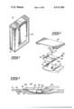
- FIG. 1 is a view in perspective of a typical personalized radio receiver apparatus which includes a retractable mounting clip, which mounting clip arrangement has been constructed in accordance with the present invention
- FIG. 2 is an enlarged fragmentary and exploded view in perspective of the mounting clip arrangement as shown in FIG. 1 illustrating certain of the component parts thereof;
- FIG. 3 is an enlarged cross-sectional view of the mounting clip and curved base plate positioned within a curved recess in the surface of the apparatus housing and illustrating the limits of respective slidable positions therein.
- FIG. 1 a radio apparatus 10 is illustrated in FIG. 1 of the personal or miniaturized type customarily intended to be carried by a user on his belt or in a shirt pocket. It is to be understood that the invention is not to be limited to any particular type of portable apparatus and in vact may be made applicable to a wide variety of such apparatus.
- a mounting clip arrangement indicated generally at 20 is shown attached to a housing 12 of a portable, miniaturized radio apparatus 10, which clip arrangement 20 has been constructed in accordance with the present invention.
- the mounting clip arrangement 20 includes a curved base plate 22 and a conventional mounting clip 24 attached thereto at a top hinged portion 24a by any suitable means such as a connecting lock or pivot pin. At least one torsion spring 38 is included to provide the required spring bias for clip 24.
- Base plate 22 includes a centrally located elongated slot 22a which is dimensioned to overfit an upstanding fastener, such as machine screw 32, extending upwardly from the surface of the housing 12.
- the base plate 22 is secured to and captivated by the fastener 32 by a guide block 34 which threads onto screw 32 and extends beyond the lateral dimensions of the slot 22a and provides a guide surface for the base plate 22 parallel to the arcuate recess surface.
- Base plate 22 may thus be slidably positioned along a path defined by the slot 22a, with the respective ends thereof functioning as stops bearing against the screw 32.
- the base plate 22 includes a hinge member 22b at one end therof.
- the mounting clip 24 includes a pair of hinge members 24a.
- Mounting clip 24 and base plate 22 are firmly secured together by a connecting or lock pin 36 inserting through respective hinge members 22b and 24a. In this manner, mounting clip 24 is rendered pivotable about pin 36 by asserting pressure on the clip area extending beyond the hinge 24a in the conventional manner.
- a pair of torsion springs 38 are carried on the pin 36 and provide a permanent spring bias for mounting clip 24 toward the base plate 22.
- the base plate 22, to which mounting clip 24 is secured to in the manner previously described, is secured within recess 30 by the mounting bolt 32 and cooperating guide block 34.
- the base plate 22 slidably moves to a position where the attached mounting clip 24 is substantially flush with the surface of housing 12. In this position, the forward U-shaped portion 24c of the mounting clip 24 is positioned within a further recess 40.
- finger pressure is exerted on the mounting clip 24 so as to move it to the right (viewing FIG.
- the curved base plate 22 is slidably moved to a position forcing the hinged end of mounting clip 24 up and outwardly where it is maintained at a position slightly above the surface of the housing 12, as depicted in phantom line in FIG. 3.
- the forward U-shaped portion 24c now rests on a raised portion or ledge 42 at approximately the same height as the overall surface of the apparatus housing 12. This ledge in cooperation with the underside of portion 24c of mounting clip 24 clamps therebetween a part of the shirt pocket or other clothing of the user.
- the U-shaped portion 24c is positioned so as to capture a portion of the belt.
- the mounting clip 24 is operated in the conventional manner, i.e., pressing downwardly on the hinged portion to the right of locking pin 36 (viewing FIG. 3) which forces the end portion 24c upwardly and outwardly and pivots around the pin 36. Release of the mounting clip then permits the forward portion 24c to move inwardly under the spring bias pressure of the torsion springs 38.
Abstract
A retractable mounting clip arrangement is provided for use with miniaturized, hand-held apparatus intended to be worn on the person of the user such as on a belt or in the shirt pocket. The clip arrangement includes a curved base plate assembly designed to position with a corresponding curved recess in the apparatus housing. A mounting clip, preferably formed of a thin steel strip is pivotably hinged to the base plate. The base plate is made to slide within the curved recess so that in one position the mounting clip is substantially flush with the surface of the housing and in still another slidable position the mounting clip is positioned entirely above the housing surface and operable to clamp onto a shirt pocket or belt.
Description
The present invention relates generally to mounting clips and, more particularly, to a fully retractable mounting clip arrangement especially suited for use with personalized radio receivers which may be readily and conveniently retracted to a position flush with the surface of the apparatus housing.
Personalized radio apparatus and other devices of this character are intended to be worn on the belt or carried in a shirt pocket of the user. This requires a mounting clip arrangement of some sort whereby the portable apparatus can be securely attached to the belt or shirt pocket so as to avoid damage by inadvertent droppage or the like.
However, in some instances, the clip arrangement actually used is of a substantial bulk when compared to the radio housing itself and can cause a number of undesirable problems. For example, in servicing or maintenance operations, the clip assembly can become snagged in test leads of monitoring equipment or in other materials in close proximity. Then too, it creates a problem for battery charging equipment in that the entrance opening thereto is of a more complicated configuration than the otherwise rather simple rectangular opening if no clip assembly were included or protruding on the radio apparatus. In any event, with the size of the miniaturized or personal radio apparatus decreasing substantially in recent years, the size of the mounting clip becomes more and more prominent and, in many instances, less desirable.
Accordingly, it is an object of the present invention to provide a completely retractable mounting clip arrangement for personalized radio apparatus or the like.
A more particular object of the present invention is to provide a mounting clip arrangement of the foregoing type which is fully retractable between a position where the mounting clip is above the housing surface to a position completely flush with the housing surface.
In practicing the invention, a retractable mounting clip arrangement is provided for use with associated miniaturized radio receiver or other portable apparatus, which mounting clip arrangement included a curved base plate which is adapted for slidable retention within a corresponding recess provided in the housing surface of the miniaturized apparatus. A thin but sturdy mounting clip is secured to the base plate by a hinge and lock pin combination. In one slidable position, the mounting clip is fully retractable to a position wherein the mounting slip is substantially flush with the surface of the apparatus housing. In the other slidable position the mounting clip extends above the surface of the housing and is operable to clamp on a user's shirt pocket or belt in the conventional manner.
The features of the present invention which are believed to be novel are set forth with particularity in the appended claims. The invention, itself, together with further objects and advantages thereof, may best be understood by reference to the accompanying drawings, in which:
FIG. 1 is a view in perspective of a typical personalized radio receiver apparatus which includes a retractable mounting clip, which mounting clip arrangement has been constructed in accordance with the present invention;
FIG. 2 is an enlarged fragmentary and exploded view in perspective of the mounting clip arrangement as shown in FIG. 1 illustrating certain of the component parts thereof; and
FIG. 3 is an enlarged cross-sectional view of the mounting clip and curved base plate positioned within a curved recess in the surface of the apparatus housing and illustrating the limits of respective slidable positions therein.
Referring now to the drawings, a radio apparatus 10 is illustrated in FIG. 1 of the personal or miniaturized type customarily intended to be carried by a user on his belt or in a shirt pocket. It is to be understood that the invention is not to be limited to any particular type of portable apparatus and in vact may be made applicable to a wide variety of such apparatus. In any event, a mounting clip arrangement indicated generally at 20 is shown attached to a housing 12 of a portable, miniaturized radio apparatus 10, which clip arrangement 20 has been constructed in accordance with the present invention.
As may be best seen in FIG. 3, the mounting clip arrangement 20 includes a curved base plate 22 and a conventional mounting clip 24 attached thereto at a top hinged portion 24a by any suitable means such as a connecting lock or pivot pin. At least one torsion spring 38 is included to provide the required spring bias for clip 24.
As illustrated, a recess 30 is provided in the surface of the apparatus housing 12 which has a curved or arcuate bottom area which corresponds substantially to that effected for the curved base plate 22. Base plate 22 includes a centrally located elongated slot 22a which is dimensioned to overfit an upstanding fastener, such as machine screw 32, extending upwardly from the surface of the housing 12. The base plate 22 is secured to and captivated by the fastener 32 by a guide block 34 which threads onto screw 32 and extends beyond the lateral dimensions of the slot 22a and provides a guide surface for the base plate 22 parallel to the arcuate recess surface. Base plate 22 may thus be slidably positioned along a path defined by the slot 22a, with the respective ends thereof functioning as stops bearing against the screw 32.
The base plate 22 includes a hinge member 22b at one end therof. Similarly, the mounting clip 24 includes a pair of hinge members 24a. Mounting clip 24 and base plate 22 are firmly secured together by a connecting or lock pin 36 inserting through respective hinge members 22b and 24a. In this manner, mounting clip 24 is rendered pivotable about pin 36 by asserting pressure on the clip area extending beyond the hinge 24a in the conventional manner. A pair of torsion springs 38 are carried on the pin 36 and provide a permanent spring bias for mounting clip 24 toward the base plate 22.
In operation, the base plate 22, to which mounting clip 24 is secured to in the manner previously described, is secured within recess 30 by the mounting bolt 32 and cooperating guide block 34. When finger pressure is exerted on the mounting clip 24 to move it to a position to the left (viewing FIG. 3), the base plate 22 slidably moves to a position where the attached mounting clip 24 is substantially flush with the surface of housing 12. In this position, the forward U-shaped portion 24c of the mounting clip 24 is positioned within a further recess 40. Correspondingly, when finger pressure is exerted on the mounting clip 24 so as to move it to the right (viewing FIG. 3) the curved base plate 22 is slidably moved to a position forcing the hinged end of mounting clip 24 up and outwardly where it is maintained at a position slightly above the surface of the housing 12, as depicted in phantom line in FIG. 3. At the same time, the forward U-shaped portion 24c now rests on a raised portion or ledge 42 at approximately the same height as the overall surface of the apparatus housing 12. This ledge in cooperation with the underside of portion 24c of mounting clip 24 clamps therebetween a part of the shirt pocket or other clothing of the user. When worn on the belt, the U-shaped portion 24c is positioned so as to capture a portion of the belt. The mounting clip 24 is operated in the conventional manner, i.e., pressing downwardly on the hinged portion to the right of locking pin 36 (viewing FIG. 3) which forces the end portion 24c upwardly and outwardly and pivots around the pin 36. Release of the mounting clip then permits the forward portion 24c to move inwardly under the spring bias pressure of the torsion springs 38.
Accordingly, while only a specific embodiment of the present invention is shown and described herein, it will, of course, be understood that other variations and modifications may be effected without departing from the true scope and spirit of the invention itself. The claims as appended hereto are intended to cover all such modifications and alternative constructions that may fall within the true scope and spirit.
Claims (5)
1. A retractable mounting clip arrangement especially suited for use with portable, hand-held apparatus intended to be worn on a person, including in combination:
a housing
a recess provided in a surface of said housing and including an arcuate bottom surface area;
a curved base plate for positioning within said recess and slidable along said arcuate bottom surface of said recess between first and second fixed positions;
an elongated mounting clip pivotably secured to said base plate; and
means for slidably securing said curved base plate within said housing recess,
said mounting clip being substantially flush with the surface of said housing when said base plate and attached mounting clip is in said first and slidable position, and wherein said mounting clip is at a level above the surface of said housing when said base plate and attached mounting clip is in said second slidable position.
2. A retractable mounting clip arrangement in accordance with claim 1 wherein a mounting post extends upwardly from said bottom of said recess and wherein said base plate includes an elongated slot along the longitudinal axis thereof for overfitting said mounting post.
3. A retractable mounting clip arrangement in accordance with claim 2 wherein said base plate is slidably secured to said mounting post by a fastener threadably received on said mounting post and overlying a portion of said base plate and constituting a guide surface parallel to the arcuate bottom of the recess through which said mounting post extends.
4. A retractable mounting clip arrangement in accordance with claim 1 wherein said base plate and mounting clip include respective hinge portions and wherein said mounting clip is pivotably secured to said base plate by a locking pin insertable within said hinge portions thereof.
5. A retractable mounting clip arrangement in accordance with claim 4 wherein at least one torsion spring is mounted on said locking pin to provide a set spring bias for said mounting clip.
Priority Applications (1)
| Application Number | Priority Date | Filing Date | Title |
|---|---|---|---|
| US05/790,712 US4111343A (en) | 1977-04-25 | 1977-04-25 | Retractable mounting clip arrangement for miniature portable apparatus or the like |
Applications Claiming Priority (1)
| Application Number | Priority Date | Filing Date | Title |
|---|---|---|---|
| US05/790,712 US4111343A (en) | 1977-04-25 | 1977-04-25 | Retractable mounting clip arrangement for miniature portable apparatus or the like |
Publications (1)
| Publication Number | Publication Date |
|---|---|
| US4111343A true US4111343A (en) | 1978-09-05 |
Family
ID=25151542
Family Applications (1)
| Application Number | Title | Priority Date | Filing Date |
|---|---|---|---|
| US05/790,712 Expired - Lifetime US4111343A (en) | 1977-04-25 | 1977-04-25 | Retractable mounting clip arrangement for miniature portable apparatus or the like |
Country Status (1)
| Country | Link |
|---|---|
| US (1) | US4111343A (en) |
Cited By (20)
| Publication number | Priority date | Publication date | Assignee | Title |
|---|---|---|---|---|
| US4635836A (en) * | 1983-12-07 | 1987-01-13 | Motorola, Inc. | Twist-off detachable belt clip assembly |
| US4754528A (en) * | 1987-07-24 | 1988-07-05 | Lyons Robert M | Belt lock device for hand held object |
| US4828153A (en) * | 1983-12-07 | 1989-05-09 | Motorola, Inc. | Detachable belt clip assembly |
| US4897898A (en) * | 1988-08-24 | 1990-02-06 | Cooper Industries, Inc. | Adjustable tape measure clip |
| US4956895A (en) * | 1986-12-25 | 1990-09-18 | Nec Corporation | Removable clip for portable equipment |
| US5016326A (en) * | 1989-08-09 | 1991-05-21 | Goldenberg Michael P | Belt clip |
| US5038985A (en) * | 1988-08-24 | 1991-08-13 | Cooper Industries | Adjustable tape measure clip |
| US5711085A (en) * | 1996-05-21 | 1998-01-27 | Adams; Thomas F. | Writing instrument holding clip for retractable tape |
| US5730348A (en) * | 1997-04-11 | 1998-03-24 | Tien; Tse-Hsiung | Fastening for securing an apparatus to a belt |
| US6018848A (en) * | 1998-04-06 | 2000-02-01 | Motorola, Inc. | Belt clip having integrated electrical connector protective cover retention area and method of using same |
| US6233789B1 (en) * | 1998-04-02 | 2001-05-22 | Dennis Douglas | Square tool with tape measure |
| US6421885B1 (en) * | 1998-09-17 | 2002-07-23 | Rehabilicare, Inc. | Battery holder |
| US6441872B1 (en) * | 2001-10-15 | 2002-08-27 | Photic Electronics Co., Ltd. | Vehicle reversal monitoring device mounting fixture |
| US6481058B1 (en) * | 1999-08-24 | 2002-11-19 | Telefonaktiebolaget Lm Ericsson (Publ) | Accessory for a portable apparatus |
| US6553631B1 (en) | 2001-11-08 | 2003-04-29 | Square One Products, Inc. | Square tool with pencil clip |
| US20040129746A1 (en) * | 2003-01-06 | 2004-07-08 | Raymond Lee | Integrated retractable belt clip |
| WO2007020614A1 (en) * | 2005-08-12 | 2007-02-22 | Renata Matassa | Decorative jewellery |
| US7523526B1 (en) | 2006-02-02 | 2009-04-28 | Valois A Daniel | Flush surface mounting clip and its associated method of construction |
| US10743642B2 (en) | 2016-08-26 | 2020-08-18 | Motorola Solutions, Inc. | Retention clip for a portable communication device |
| USD894161S1 (en) * | 2020-05-11 | 2020-08-25 | Shenzhen Zhengguang Imaging Equipment Co., Ltd. | Wireless microphone |
Citations (3)
| Publication number | Priority date | Publication date | Assignee | Title |
|---|---|---|---|---|
| US1777543A (en) * | 1928-11-26 | 1930-10-07 | Carl E Bashe | Compact or container with holder |
| US2551515A (en) * | 1947-11-03 | 1951-05-01 | Francis A Newton | Watch holding device for belts |
| US3631994A (en) * | 1970-08-26 | 1972-01-04 | Gen Electric | Carrying device for a radio receiver or the like |
-
1977
- 1977-04-25 US US05/790,712 patent/US4111343A/en not_active Expired - Lifetime
Patent Citations (3)
| Publication number | Priority date | Publication date | Assignee | Title |
|---|---|---|---|---|
| US1777543A (en) * | 1928-11-26 | 1930-10-07 | Carl E Bashe | Compact or container with holder |
| US2551515A (en) * | 1947-11-03 | 1951-05-01 | Francis A Newton | Watch holding device for belts |
| US3631994A (en) * | 1970-08-26 | 1972-01-04 | Gen Electric | Carrying device for a radio receiver or the like |
Cited By (23)
| Publication number | Priority date | Publication date | Assignee | Title |
|---|---|---|---|---|
| US4635836A (en) * | 1983-12-07 | 1987-01-13 | Motorola, Inc. | Twist-off detachable belt clip assembly |
| US4828153A (en) * | 1983-12-07 | 1989-05-09 | Motorola, Inc. | Detachable belt clip assembly |
| US4956895A (en) * | 1986-12-25 | 1990-09-18 | Nec Corporation | Removable clip for portable equipment |
| US4754528A (en) * | 1987-07-24 | 1988-07-05 | Lyons Robert M | Belt lock device for hand held object |
| US4897898A (en) * | 1988-08-24 | 1990-02-06 | Cooper Industries, Inc. | Adjustable tape measure clip |
| US5038985A (en) * | 1988-08-24 | 1991-08-13 | Cooper Industries | Adjustable tape measure clip |
| US5016326A (en) * | 1989-08-09 | 1991-05-21 | Goldenberg Michael P | Belt clip |
| US5711085A (en) * | 1996-05-21 | 1998-01-27 | Adams; Thomas F. | Writing instrument holding clip for retractable tape |
| US5730348A (en) * | 1997-04-11 | 1998-03-24 | Tien; Tse-Hsiung | Fastening for securing an apparatus to a belt |
| US6233789B1 (en) * | 1998-04-02 | 2001-05-22 | Dennis Douglas | Square tool with tape measure |
| US6018848A (en) * | 1998-04-06 | 2000-02-01 | Motorola, Inc. | Belt clip having integrated electrical connector protective cover retention area and method of using same |
| US6421885B1 (en) * | 1998-09-17 | 2002-07-23 | Rehabilicare, Inc. | Battery holder |
| US6481058B1 (en) * | 1999-08-24 | 2002-11-19 | Telefonaktiebolaget Lm Ericsson (Publ) | Accessory for a portable apparatus |
| US6441872B1 (en) * | 2001-10-15 | 2002-08-27 | Photic Electronics Co., Ltd. | Vehicle reversal monitoring device mounting fixture |
| US6553631B1 (en) | 2001-11-08 | 2003-04-29 | Square One Products, Inc. | Square tool with pencil clip |
| US7063244B2 (en) * | 2003-01-06 | 2006-06-20 | Vtech Telecommunications Limited | Integrated retractable belt clip |
| US20040129746A1 (en) * | 2003-01-06 | 2004-07-08 | Raymond Lee | Integrated retractable belt clip |
| WO2007020614A1 (en) * | 2005-08-12 | 2007-02-22 | Renata Matassa | Decorative jewellery |
| US20100293699A1 (en) * | 2005-08-12 | 2010-11-25 | Renata Matassa | Decorative jewellery |
| US8127404B2 (en) | 2005-08-12 | 2012-03-06 | Renata Matassa | Decorative jewellery |
| US7523526B1 (en) | 2006-02-02 | 2009-04-28 | Valois A Daniel | Flush surface mounting clip and its associated method of construction |
| US10743642B2 (en) | 2016-08-26 | 2020-08-18 | Motorola Solutions, Inc. | Retention clip for a portable communication device |
| USD894161S1 (en) * | 2020-05-11 | 2020-08-25 | Shenzhen Zhengguang Imaging Equipment Co., Ltd. | Wireless microphone |
Similar Documents
| Publication | Publication Date | Title |
|---|---|---|
| US4111343A (en) | Retractable mounting clip arrangement for miniature portable apparatus or the like | |
| US5850954A (en) | Holder assembly for cellular phones | |
| US4083481A (en) | Detachable mounting clip arrangement for miniature portable apparatus or the like | |
| US5217150A (en) | Belt buckle with a cutting tool incorporated therein | |
| CA1313514C (en) | Housing and holder assembly for a portable communication apparatus | |
| US5185906A (en) | Belt clip spring with E-ring fastener | |
| CA1300096C (en) | Carry case with quick release and self locating retainer apparatus | |
| US6026585A (en) | Structure for a tape measure | |
| US4635836A (en) | Twist-off detachable belt clip assembly | |
| EP1463274B1 (en) | Locking mechanism | |
| US4754528A (en) | Belt lock device for hand held object | |
| KR20000000553U (en) | Holder of portable cordless phone | |
| US5531365A (en) | Belt clip incorporating a multipurpose tool | |
| WO2000008882A8 (en) | Attachment device for mobile phone | |
| US4969859A (en) | Belt tensioning apparatus | |
| CA1213438A (en) | Fastener for sport shoes | |
| US5285997A (en) | Device for locking a lever for pivoting a valve | |
| EP0491385A2 (en) | Coupling device | |
| CA2015959A1 (en) | Lightly-Operating Automatic Umbrella for Preventing False Operation | |
| US5275186A (en) | Fastening assembly for an umbrella | |
| EP0234448A3 (en) | Insertion tool | |
| US7434239B2 (en) | Disc player with opening and closing mechanism | |
| US4010340A (en) | Switch member for portable, battery-operated apparatus | |
| AU4131799A (en) | Device for climbing | |
| GR3008586T3 (en) |