US408317A - Machine for hemming can-caps with sheet-solder rings - Google Patents
Machine for hemming can-caps with sheet-solder rings Download PDFInfo
- Publication number
- US408317A US408317A US408317DA US408317A US 408317 A US408317 A US 408317A US 408317D A US408317D A US 408317DA US 408317 A US408317 A US 408317A
- Authority
- US
- United States
- Prior art keywords
- dies
- die
- carrier
- machine
- gang
- Prior art date
- Legal status (The legal status is an assumption and is not a legal conclusion. Google has not performed a legal analysis and makes no representation as to the accuracy of the status listed.)
- Expired - Lifetime
Links
- 229910000679 solder Inorganic materials 0.000 title description 42
- 238000009957 hemming Methods 0.000 title 2
- 239000000969 carrier Substances 0.000 description 82
- 239000000203 mixture Substances 0.000 description 46
- 210000001699 lower leg Anatomy 0.000 description 14
- 230000000875 corresponding Effects 0.000 description 6
- 240000002444 Sphenoclea zeylanica Species 0.000 description 2
- 238000010276 construction Methods 0.000 description 2
- 238000004519 manufacturing process Methods 0.000 description 2
- 239000002184 metal Substances 0.000 description 2
- 230000036633 rest Effects 0.000 description 2
Images


Classifications
-
- B—PERFORMING OPERATIONS; TRANSPORTING
- B29—WORKING OF PLASTICS; WORKING OF SUBSTANCES IN A PLASTIC STATE IN GENERAL
- B29C—SHAPING OR JOINING OF PLASTICS; SHAPING OF MATERIAL IN A PLASTIC STATE, NOT OTHERWISE PROVIDED FOR; AFTER-TREATMENT OF THE SHAPED PRODUCTS, e.g. REPAIRING
- B29C31/00—Handling, e.g. feeding of the material to be shaped, storage of plastics material before moulding; Automation, i.e. automated handling lines in plastics processing plants, e.g. using manipulators or robots
- B29C31/04—Feeding of the material to be moulded, e.g. into a mould cavity
- B29C31/08—Feeding of the material to be moulded, e.g. into a mould cavity of preforms to be moulded, e.g. tablets, fibre reinforced preforms, extruded ribbons, tubes or profiles; Manipulating means specially adapted for feeding preforms, e.g. supports conveyors
Definitions
- Our invention relates to the manufacture of solder-hemmed can-caps, such as are shown in and described in Patent No. 36%,662, granted to Edwin Norton June 14, 1887.
- the object of our invention is to provide a machine for securing sheet-solder rings to can caps or heads rapidly and cheaply.
- our invention consists in the combination of a flexible movable carrier furnished with gangs of dies for holding and supporting the can-caps and their sheet-solder rings and of a corresponding gang of punchcs operating in conjunction with said dies to simultaneously close the solder rings upon the cancaps.
- the dies are each mount-ed movably in the carrier, and are automatically reciprocated or moved to discharge the solderhemmed caps therefrom.
- the carrier preferably consists of a link chain mounted .upon l'lorizontal rollers or polygon wheels, though it may be of other suitable construction.
- solder rings may be very rapidly and cheaply closed upon the can-caps, as by reason of the several sets of gang-dies on the movable carrier the operators maybe placing the caps and rings in one gang of dies while another gang of dies are under the punches, and while the hemmed caps are being discharged from still another gang of dies.
- Our invention also consists in the novel devices and novel combinations of parts and devices herein shown and described, and more particularly pointed out in the claims.
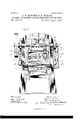
- Figure 1 is a front view of a machine embodying our invention.
- Fig. 2 is a side elevation.
- Fig. 3 is a longitudinal vertical section.
- Fig. 4 is an enlarged detail vertical section showing the form of the dies.
- Fig. 5 is a sectional view showing a can-cap and its solder ring before the latter is closed upon the former by the machine.
- Fig. 6 is a similar View showing the solder ring securely closed
- 7 is a detail view of the friction-brake hereinafter mentioned.
- A represents the frame of the machine.
- B is a movable die-carrier, preferably consisting of a link chain mounted 011 rollers or polygon wheels 13 B
- the frame A has guides or ways B B extending between the polygon Wheels for guiding and supporting the flexible die-carrier.
- C O are the female dies mounted on the carrier B and preferably arranged in gangs or sets extending transversely across the carrier.
- D D are the male dies or punches mounted to reciprocate on the frame of the machine and extending across the machine, so that the gang of male dies will register with the gangs of female dies as each gang is in turn brought into position by the intermittentlymoving die-carrier B.
- Each link Z) of the chain-carrier B preferably consists of a cast-metal plate having hinges I) I) at its side edges, by which it is connected to the adjoining links, and pro- Vided with sockets or guides b to receive the shanks c of the gang of dies C.
- the shank c of the die 0 is adapted to reciprocate in the guide 0*, and the link I) is furnished with recesses b, to receive the dies 0 flush with the upper surface of the link-plate.
- the die C is furnished with a beveled corner 0', which, in conjunction with the wall of the recess 1), forms an annular groove to receive the solder ring as as it fits upon the depending flange w of the can-cap 00 E is a reciprocating bar or cross-head, by. means of which each gang of dies 0 is in turn supported to resist the thrust of the opposing dies D when the dies 0 are brought into position by the carrier B.
- This bar or crosshead also serves to give the dies 0 a vertical movement in opposition to the dies D in cases where such movement of the dies 0 is desirable.
- the gang of dies D are secured in a movable head E, which is reciprocated in suitable guides F on the frame of the machine by cams F on the driving-shaft G.
- the die I) has a movable follower or central portion (1, which is provided with a beveled flange d.
- the follower d is secured to a sliding stem d and rests upon coiled springs d
- a pin d holds the stem 01 in place.
- the outer rim of the die D is in wardly beveled, as shown at (1 As the die D descends, the bevel d bends or inclines the upwardly-projecting outer edge of the solder ring it inward over the flange 00' of the cancap.
- the outer wall of the recess b is beveled off, as shown at 11 and the lower edge of the die D is correspondingly beveled, as shown at 61, so that the opposing dies 0 and D willalways accurately register with each other.
- the stem (1 is made hollow, to receive the extractor-pin al which is provided with a pin or projection 01 which extends through a slot d in the hollow stem 01 This extractor-pin d is furnished with a conical end to fit in the vent-hole 00 of the can-cap.
- the slot (Z in the stem (1 permits the pin d to telescope out of the way when the die D makes its stroke against the opposing die C, and the pin by its own weight serves to disengage the can-cap from the follower d in case the cap should cling thereto.
- the follower d is actuated by the stem (1 to which it is secured,-which stem, impinging against the cam-operated cross-bar N, causes the can-cap, with its solder ring, to be ejected from the die D.
- the reciprocating bar or cross-head E is operated by cams E, which operate the slides E
- the slides E are connected by links E with the cross-head E.
- E are the guides in which the slides E reciprocate.
- the carrier B is intermittently moved forward after each stroke of the plunger F by means of a crank g on the driving-shaft G, which is connected by a link g with a bent lever g carrying a pawl g which engages projections b on the carrier B. Any other or equivalent mechanism may, however, be employed for intermittently moving the carrier B.
- the polygon wheel B is furnished with a rim or projection B against which the inner ends of the die-stems c impinge, so as to force the dies 0 out of the recesses 12 in the link-plates b, and thus discharge the solder-hemmed cap from the die as the same passes around the pulley or wheel B.
- a discharge-chute H may receive the caps as they are delivered from the machine.
- a chute K extends from the belt K to the carrier. As the assembled caps and rings slide down the chute upon the carrier 13, one or more attendants on each side of the machine position the caps in the annular grooves or seats of the dies 0.
- L is a friction-brake, with which the pulley B is provided to prevent any danger of the carrier being moved too far by the pawllever for the gang of dies 0 to properly register with the gang of opposing dies D.
- the gang of extractor-stems 01 by which the blanks are ejected from the dies D, are all simultaneously operated by a movable cross-bar N, mounted on the cross-head F.
- the cross-bar N is operated by the cams or projections 01 on the cam-wheels F.
- the ejector-stems (Z are positively operated and without springs, the action of springs being always more or less uncertain.
- the extractor stem or pins d being thus positively operated by revolving cams, the jars and danger incident to causing the ejectingpins or their operating-bar to impinge against fixed stops on the frame of the machine are entirely avoided, and at the same time a much easier and more efficient and satisfactory action is given. to the whole machine.
- havin 'uides b and recess b of die 0 having shank c and bevel-corner c, forming with said recess Z7 an annular groove to receive the solder ring and can-cap, and an opposing die D, having central portion d, provided with bevel-flange d for closing the solder ring upon the can-cap, sliding stem (Z and spring d substantially as specified.
- shank c and bevel-corner c forming with said recess 1) an annular groove to receive the solder ring and can-cap, and an opposing die D, having central portion d, provided with bevel-flange d for closing the solder ring upon the can-cap, sliding stem (1 and spring (1, said sliding stem at being hollow and furnished with an extractor-pin d substantially as specified.
- rollers B B said roller B having a rim B against which the shanks of said dies imister of the dies on the carrier with the oppinge as the link chain passes aroundsaid posingdie on the frame, substantially as speei- 1o roller, substantially as specified. fiecl.
Description
(No Model.) v 3 Sheets-Sheet 1.
J. G. HODGSON & E. NORTON. MACHINE FOR HEMMING CAN GAPS WITH SHEET SOLDER RINGS.
No. 408,317. I Patented Aug. 6, 1889.
m PETilii Pholo-uihagraplmr. Wzsmngtnn, nj-c.
(No Model) 3 Sheets-Sheet 2.
J. G. HODGSON & E. NORTON. MACHINE FOR HEMMING CAN GAPS WITH SHEET SOLDER RINGS.
No. 408,317. Patented A11'g.6, 1889.
Japan f0 r6. Edwin flraow $271 451022 5? gym F (No Model.) 3 Sheets-Sheet 3'.
J. G. HODGSON & E. NORTON. MACHINE FOR HEMMING CAN GAPS WITH SHEET SOLDER RINGS.
No. 408,317. Patented Aug. 6, 1889.
77557263868: Q jkveflfari N. Puma Fhoto-Lflhognyhzn Washinglon. n. r;
' UNITED STATES PATENT OFFICE.
JOHN G. I-IODGSON AND ED'WIN NORTON, OF MAYIVOOD, ASSIGNORS TO SAID EDWIN NORTON, AND OLIVER IV. NORTON, OFLIIIOAGO, ILLINOIS.
MACHINE FOR HEMMING CAN-CAPS WITH SHEET-SOLDER RINGS.
SPECIFICATION forming part of Letters Patent No. 408,317, dated August 6, 1889. Application filed October 15, 1888. Serial No. 288,055- [No model.)
To all whom it may concern:
Be it known that we, JOHN G. IIODGSON and EDWIN NORTON, citizens of .the United States, residing at Maywood,in the county of Cook and State of Illinois, have invented a new and useful Improvement in Machines for llemmin g Can-Caps with Sheet-Solder Rings, of which the following isa specification.
Our invention relates to the manufacture of solder-hemmed can-caps, such as are shown in and described in Patent No. 36%,662, granted to Edwin Norton June 14, 1887.
The object of our invention is to provide a machine for securing sheet-solder rings to can caps or heads rapidly and cheaply.
To this end our invention consists in the combination of a flexible movable carrier furnished with gangs of dies for holding and supporting the can-caps and their sheet-solder rings and of a corresponding gang of punchcs operating in conjunction with said dies to simultaneously close the solder rings upon the cancaps. The dies are each mount-ed movably in the carrier, and are automatically reciprocated or moved to discharge the solderhemmed caps therefrom. The carrier preferably consists of a link chain mounted .upon l'lorizontal rollers or polygon wheels, though it may be of other suitable construction. It is preferable to mount the gangs of female dies upon the carrier and the punches or male dies upon the stationary frame of the machine, as the can-caps and their solder rings may be more conveniently placed in the female than in the male die. By this means the solder rings may be very rapidly and cheaply closed upon the can-caps, as by reason of the several sets of gang-dies on the movable carrier the operators maybe placing the caps and rings in one gang of dies while another gang of dies are under the punches, and while the hemmed caps are being discharged from still another gang of dies.
IVhile our combined gang-dies and gangdie carrier is specially designed for closing solder rings upon can-caps, it may, nevertheless, be used for other purposes by simply changing the shape of the dies, as may be required to adaptthem to other work.
Our invention also consists in the novel devices and novel combinations of parts and devices herein shown and described, and more particularly pointed out in the claims.
In the accompanying drawings, which form a part of this specification, and in which similar letters of reference indicate like parts, Figure 1 is a front view of a machine embodying our invention. Fig. 2 is a side elevation. Fig. 3 is a longitudinal vertical section. Fig. 4is an enlarged detail vertical section showing the form of the dies. Fig. 5 is a sectional view showing a can-cap and its solder ring before the latter is closed upon the former by the machine. Fig. 6 is a similar View showing the solder ring securely closed, and 7 is a detail view of the friction-brake hereinafter mentioned.
In said drawings, A represents the frame of the machine. B is a movable die-carrier, preferably consisting of a link chain mounted 011 rollers or polygon wheels 13 B The frame A has guides or ways B B extending between the polygon Wheels for guiding and supporting the flexible die-carrier.
C O are the female dies mounted on the carrier B and preferably arranged in gangs or sets extending transversely across the carrier.
D D are the male dies or punches mounted to reciprocate on the frame of the machine and extending across the machine, so that the gang of male dies will register with the gangs of female dies as each gang is in turn brought into position by the intermittentlymoving die-carrier B.
Each link Z) of the chain-carrier B preferably consists of a cast-metal plate having hinges I) I) at its side edges, by which it is connected to the adjoining links, and pro- Vided with sockets or guides b to receive the shanks c of the gang of dies C. The shank c of the die 0 is adapted to reciprocate in the guide 0*, and the link I) is furnished with recesses b, to receive the dies 0 flush with the upper surface of the link-plate. The die C is furnished with a beveled corner 0', which, in conjunction with the wall of the recess 1), forms an annular groove to receive the solder ring as as it fits upon the depending flange w of the can-cap 00 E is a reciprocating bar or cross-head, by. means of which each gang of dies 0 is in turn supported to resist the thrust of the opposing dies D when the dies 0 are brought into position by the carrier B. This bar or crosshead also serves to give the dies 0 a vertical movement in opposition to the dies D in cases where such movement of the dies 0 is desirable.
The gang of dies D are secured in a movable head E, which is reciprocated in suitable guides F on the frame of the machine by cams F on the driving-shaft G.
The die I) has a movable follower or central portion (1, which is provided with a beveled flange d. The follower d is secured to a sliding stem d and rests upon coiled springs d A pin d holds the stem 01 in place. The outer rim of the die D is in wardly beveled, as shown at (1 As the die D descends, the bevel d bends or inclines the upwardly-projecting outer edge of the solder ring it inward over the flange 00' of the cancap. The outer wall of the recess b is beveled off, as shown at 11 and the lower edge of the die D is correspondingly beveled, as shown at 61, so that the opposing dies 0 and D willalways accurately register with each other. The stem (1 is made hollow, to receive the extractor-pin al which is provided with a pin or projection 01 which extends through a slot d in the hollow stem 01 This extractor-pin d is furnished with a conical end to fit in the vent-hole 00 of the can-cap. The slot (Z in the stem (1 permits the pin d to telescope out of the way when the die D makes its stroke against the opposing die C, and the pin by its own weight serves to disengage the can-cap from the follower d in case the cap should cling thereto. The follower d is actuated by the stem (1 to which it is secured,-which stem, impinging against the cam-operated cross-bar N, causes the can-cap, with its solder ring, to be ejected from the die D.
The reciprocating bar or cross-head E is operated by cams E, which operate the slides E The slides E are connected by links E with the cross-head E. E are the guides in which the slides E reciprocate. After the die D descends against the link I) the die 0 is given an upward movement by the bar E, to force the follower (Z against its seat in the die D and snugly close the solder ring around the flange of the can-cap.
The carrier B is intermittently moved forward after each stroke of the plunger F by means of a crank g on the driving-shaft G, which is connected by a link g with a bent lever g carrying a pawl g which engages projections b on the carrier B. Any other or equivalent mechanism may, however, be employed for intermittently moving the carrier B. The polygon wheel B is furnished with a rim or projection B against which the inner ends of the die-stems c impinge, so as to force the dies 0 out of the recesses 12 in the link-plates b, and thus discharge the solder-hemmed cap from the die as the same passes around the pulley or wheel B. A discharge-chute H may receive the caps as they are delivered from the machine.
K represents a conveyer-belt, by which the caps and solder rings after being assembled, as indicated in Fig. 5, are conveyed to the carrier B. A chute K extends from the belt K to the carrier. As the assembled caps and rings slide down the chute upon the carrier 13, one or more attendants on each side of the machine position the caps in the annular grooves or seats of the dies 0.
L is a friction-brake, with which the pulley B is provided to prevent any danger of the carrier being moved too far by the pawllever for the gang of dies 0 to properly register with the gang of opposing dies D.
In the drawings we have shown the dies 0 and D of a shape suitable for doing one special kind of work; but it is obvious that other suitable forms of dies may be used. I
The gang of extractor-stems 01 by which the blanks are ejected from the dies D, are all simultaneously operated by a movable cross-bar N, mounted on the cross-head F. The cross-bar N is operated by the cams or projections 01 on the cam-wheels F By this means the ejector-stems (Z are positively operated and without springs, the action of springs being always more or less uncertain. The extractor stem or pins d being thus positively operated by revolving cams, the jars and danger incident to causing the ejectingpins or their operating-bar to impinge against fixed stops on the frame of the machine are entirely avoided, and at the same time a much easier and more efficient and satisfactory action is given. to the whole machine.
By combining the intermittently-moving die-carrier with its series of dies with a reciprocating die mounted on the stationary frame of the machine we are enabled to bring the faces of the opposing dies to bear flat and smooth upon the interposed sheet, and thus secure the same perfect action of the dies as has heretofore been done where both the dies are mounted directly upon the stationary frame of the machine.
\Ve claim- 1. The combination, with an intermittentlymovable flexible die-carrierfurnished with dies, of an opposing reciprocating die and a guide B for supporting and guiding said diecarrier, substantially as specified.
2. The combination of an intermittently- V movable flexible die-carrier furnished with dies, rollers or wheels upon which said carrier is mounted, and an opposing reciprocating die, substantially as specified.
3. The combination of an intermittentlymoving endless link chain die-carrier fur- 'nished with dies, rollers upon which it is mounted, and an opposing die, substantially as specified.
4. The combination of a movable die-carrier having independently movable dies mounted thereon, an opposingdie, and means for supporting the dies in said carrier against the thrust of said opposing die, substantially as specified.
5. The combination,with an intermittentlymovable die-carrier having independentlymovable dies mounted thereon, of an opposing reciprocating die mounted on the frame of the machine and means for automatically moving or reciprocating the dies in said carrier to discharge the work therefrom, substantially as specified.
6. The combination, with an endless link chain die-carrier furnished with independently-movable dies, of rollers upon which said carrier is mounted, one of .said rollers being furnished with a projection or rim for moving the dies in said carrier to discharge the work therefrom, substantially as specified.
7. The combinatiomwith an intermittently moving flexible diecarrier having gangs of dies arranged transversely to its line of movement, of a corresponding gang of opposing reciprocating dies and a guide or way B for supporting and guiding said'die-carrier, substantially as specified.
8. The combination of an intermittently movable link chain gang die-carrier having gangs of dies in the links thereof, rollers upon which said carrieris mounted, and an opposing gang of reciprocating dies mounted on the frame of the machine, substantially as specified.
9. The combination, with the gang of reciprocating dies mounted on the frame of the machine, of an intermittently-moving diecarrierfurnished with gangs of dies mounted movably thereon and a bar or support to sustain said movably-mounted dies, nubstantially as specified.
10. The combination, with the gang of dies,
mounted on the frame of the machine, of an intermittentlyrmoving die-carrier furnished with gangs of dies mounted movably thereon and a movable cross-head or bar for simultaneously actuating the gang of dies on the carrier, substantially as specified.
11. The combination, with an intermittently-moving link-chain die-carrier having gangs of dies mounted movably thereon, of rollers upon which said carrier is mounted, one of said rollers being furnished with rings or projections for simultaneously operating each gang of movable dies to discharge the work therefrom as the same pass around the roller, substantially as specified.
12. The combination, with a reciprocating die mounted on the frame of the machine, of an intermittently-movable die-carrier having movable dies mounted thereon, means for automatically moving said dies to discharge the work therefrom, and a discharge-chute, substantially as specified.
13. The combination, with a gang of reciprocating dies mounted 011 the frame of the machine, of an intermittntly-moving flexible die-carrier furnished with gangs of dies, a guide B for supporting and guiding said diecarrier, and a conveyer K, substantially as specified.
14. The combinatiom/with a gang of reciprocating dies mounted on the frame of the machine, of an intermittently-moving diecarrier furnished with gangs of dies, a conveyer K, and chute K, substantially as specified.
15. The combination, with a die-plate I), having guide b and recess b of die 0, having shank c and bevel-corner c, forming with said recess 19' an annular groove to receive the solder ring and can-cap, and an opposing die D, having central portion d, provided with bevel-flange d for closing the solder ring upon the can-cap, substantially as specified. r
16. The combination, with a die-plate Z),
havin 'uides b and recess b of die 0, having shank c and bevel-corner c, forming with said recess Z7 an annular groove to receive the solder ring and can-cap, and an opposing die D, having central portion d, provided with bevel-flange d for closing the solder ring upon the can-cap, sliding stem (Z and spring d substantially as specified.
17. The combination, with a gang of dies, of a reciprocating cross-head upon which they are mounted, a corresponding gang of movable ejector-pins, a cross-bar mounted movably on said cross-head for actuating said ejector-pins, and a movable cam for operating said cross-bar, substantially as specified.
18. The combination, with a die, of a reciprocating cross-head, an ejector-pin and a movable cam for positively operating said ejector-pin to discharge the blank from the die, substantially as specified.
19. The combination, with a die, of are ciprocating cross-head, cams for operating said cross-head, an ejector-pin, and a movable cam or projection 41, for operating saidejector-pin, substantially as specified.
20. The combination, with a gang of dies D, of cross-head F, cams F ejector-pins d cross-bar N, and cams or projections n on said cam, and wheels F for operating said ejector-pins, substantially as specified.
21. The combination, with die-plate Z1, having guides 19 and recess Z), of die 0, having.
shank c and bevel-corner c, forming with said recess 1) an annular groove to receive the solder ring and can-cap, and an opposing die D, having central portion d, provided with bevel-flange d for closing the solder ring upon the can-cap, sliding stem (1 and spring (1, said sliding stem at being hollow and furnished with an extractor-pin d substantially as specified.
22. The combination, with a link chain diecarrier B, composed of hinged die-plate links I), having guides b to receive the die-shanks,
of movable dies 0, having shanks c, and rollers B B said roller B having a rim B against which the shanks of said dies imister of the dies on the carrier with the oppinge as the link chain passes aroundsaid posingdie on the frame, substantially as speei- 1o roller, substantially as specified. fiecl.
23. The combination, with a die mounted JOHN G. HODGSON. on the frame of the machine, of a movable EDWIN NORTON. (lie-carrier and series of dies mounted there- Vitnesses: on, the opposing dies having bevel or conical H. M. MUNDAY, centering surfaces to insure the proper reg- EDMUND ADCOGK.
Publications (1)
| Publication Number | Publication Date |
|---|---|
| US408317A true US408317A (en) | 1889-08-06 |
Family
ID=2477255
Family Applications (1)
| Application Number | Title | Priority Date | Filing Date |
|---|---|---|---|
| US408317D Expired - Lifetime US408317A (en) | Machine for hemming can-caps with sheet-solder rings |
Country Status (1)
| Country | Link |
|---|---|
| US (1) | US408317A (en) |
-
0
- US US408317D patent/US408317A/en not_active Expired - Lifetime
Similar Documents
| Publication | Publication Date | Title |
|---|---|---|
| US4382737A (en) | Can end making apparatus | |
| US408317A (en) | Machine for hemming can-caps with sheet-solder rings | |
| US726800A (en) | Machine for the manufacture of bottle-capsules. | |
| US413667A (en) | Double-acting gang-die press | |
| US1135825A (en) | Manufacture of hollow or like earthenware. | |
| US912601A (en) | Machine for making tube-sections and similar parts. | |
| US1309938A (en) | Method for making bullets | |
| US1846319A (en) | Apparatus for preparing drumhead can bodies | |
| US1869480A (en) | Apparatus for assembling receptacle closures | |
| US336994A (en) | Machine for capping nails | |
| US761842A (en) | Dough-treating mechanism. | |
| US765988A (en) | Mechanism for forming spoons. | |
| US702376A (en) | Hemmed-cap machine. | |
| US1188423A (en) | Manufacture of eyelets or the like. | |
| US665163A (en) | Press for molding and compressing various articles. | |
| US1111000A (en) | Drawing-press. | |
| US353190A (en) | Machine for drawing cartridge-shells | |
| US3364553A (en) | Rivet assembly apparatus | |
| US1133383A (en) | Feed mechanism for can-heads. | |
| US1348560A (en) | Can-end-lining machine | |
| US1898254A (en) | Bending machine | |
| US1167059A (en) | Can-end curling, can assembling and seaming machine. | |
| US723602A (en) | Machine for flanging can-bodies. | |
| US1164103A (en) | Machine for seaming can-tops. | |
| US666573A (en) | Can-capping machine. |