US4066213A - Fuel injection nozzle assembly - Google Patents
Fuel injection nozzle assembly Download PDFInfo
- Publication number
- US4066213A US4066213A US05/677,779 US67777976A US4066213A US 4066213 A US4066213 A US 4066213A US 67777976 A US67777976 A US 67777976A US 4066213 A US4066213 A US 4066213A
- Authority
- US
- United States
- Prior art keywords
- nozzle
- hollow screw
- annular groove
- nozzle holder
- cylinder head
- Prior art date
- Legal status (The legal status is an assumption and is not a legal conclusion. Google has not performed a legal analysis and makes no representation as to the accuracy of the status listed.)
- Expired - Lifetime
Links
Images
Classifications
-
- F—MECHANICAL ENGINEERING; LIGHTING; HEATING; WEAPONS; BLASTING
- F02—COMBUSTION ENGINES; HOT-GAS OR COMBUSTION-PRODUCT ENGINE PLANTS
- F02M—SUPPLYING COMBUSTION ENGINES IN GENERAL WITH COMBUSTIBLE MIXTURES OR CONSTITUENTS THEREOF
- F02M61/00—Fuel-injectors not provided for in groups F02M39/00 - F02M57/00 or F02M67/00
- F02M61/14—Arrangements of injectors with respect to engines; Mounting of injectors
-
- F—MECHANICAL ENGINEERING; LIGHTING; HEATING; WEAPONS; BLASTING
- F02—COMBUSTION ENGINES; HOT-GAS OR COMBUSTION-PRODUCT ENGINE PLANTS
- F02M—SUPPLYING COMBUSTION ENGINES IN GENERAL WITH COMBUSTIBLE MIXTURES OR CONSTITUENTS THEREOF
- F02M2200/00—Details of fuel-injection apparatus, not otherwise provided for
- F02M2200/26—Fuel-injection apparatus with elastically deformable elements other than coil springs
-
- F—MECHANICAL ENGINEERING; LIGHTING; HEATING; WEAPONS; BLASTING
- F02—COMBUSTION ENGINES; HOT-GAS OR COMBUSTION-PRODUCT ENGINE PLANTS
- F02M—SUPPLYING COMBUSTION ENGINES IN GENERAL WITH COMBUSTIBLE MIXTURES OR CONSTITUENTS THEREOF
- F02M2200/00—Details of fuel-injection apparatus, not otherwise provided for
- F02M2200/85—Mounting of fuel injection apparatus
- F02M2200/856—Mounting of fuel injection apparatus characterised by mounting injector to fuel or common rail, or vice versa
Definitions
- the present invention relates generally to fuel injection nozzle assemblies for internal combustion engines, and more particularly to means for holding the fuel injection nozzle assembly in position in the engine.
- a fuel injection nozzle assembly is generally mounted on the cylinder head of a diesel engine with a sealing washer disposed between the sealing face of the nozzle assemblies and a countersunk opening in the cylinder head.
- the nozzle assembly was held in position by an external clamp loaded by a long bolt screwed into the head which pressed on the top of the nozzle assembly as shown in the U.S. Pat. No. 3,038,456 granted to A. Dreisin.
- nozzle assemblies have been built having integral apertured flanges held in place by studs secured to the engine and clamped in place by springs disposed between the bolt end of the studs and the apertured flange as shown in the Great Britain Pat. 1,386,835 granted to Smith et al.
- the previous holding means have been unsatisfactory in that they have been relatively complex in requiring a large number of pieces and have been difficult to install. Further, the holding means took up a large amount of space which increased the space envelope of the engines to which they have been mounted.
- the ideal situation calls for axial loading of the nozzle holder so as to provide uniform loading to prevent leaks as the sealing washer settles. It is also desirable to accomplish this in a single integral package which may be merely inserted in the cylinder head and tightened down with one screw.
- the present invention provides a fuel injection nozzle assembly which has few parts, is easy to assemble, and is effective to prevent leaks due to sealing washer settling.
- a plurality of conical springs disposed between a hollow screw for fastening the nozzle assembly to the cylinder head and a snap ring and retaining washer combination mounted to the nozzle holder. Tightening the hollow screw loads the springs to urge the nozzle assembly against the sealing washer.
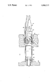
- the drawing shows in partial cross section a fuel injection nozzle assembly including the present invention.
- a cylinder head 10 provided with a coolant passage 11 and having provided therein an opening 12 and a coaxial countersunk opening 14 into which a fuel injection nozzle assembly 16 is inserted.
- the fuel injection nozzle assembly consists of a nozzle holder 18 which includes a nozzle retaining nut 20 to hold a nozzle 22 in place.
- a conventional sealing washer 24 encircles the nozzle 22 and is inserted between the nozzle retaining nut 20 and a nozzle sleeve 26.
- the nozzle holder 18 contains an annular groove 28 into which a conventional snap ring 30 is inserted.
- a retaining washer 32 having a retaining shoulder 34 abuts and encircles the snap ring 30 so as to prevent it from opening.
- Three conventional conical springs 36, 38 and 40 are positioned successively away from the retaining washer 32 and preferably positioned so as to have the smaller diameter of the conical spring 36 abutting the retaining washer 32.
- a gland nut or hollow screw 41 encircles the nozzle holder 18 and includes threads 42 for threading into the cylinder head 10 such that a portion of the hollow screw 41 will be brought into abutting relationship with the larger diameter of the conical spring 40.
- the hollow screw 41 includes a sealing ring 44.
- the nozzle holder 18 further includes an annular groove 46 into which a retaining ring 48 is inserted so as to retain the hollow screw 41 around the nozzle holder 18 before the fuel injection nozzle assembly 16 is secured in the cylinder head 10.
- the installation of the fuel injection nozzle assembly 16 begins with the nozzle sleeve 26 being inserted into the cylinder head 10 so as the bridge the coolant passage 11.
- the sealing washer 24 is placed around the tip of the nozzle 22 and the fuel injection nozzle assembly 16 inserted into the nozzle sleeve 26.
- the threads 42 of the hollow screw 41 are then engaged with the cylinder head 10 and turned until the hollow screw 41 reaches a predetermined position which applies a predetermined pre-load on the conical springs 36, 38, and 40.
- the pre-load acting through the retaining washer 32 and the snap ring 30 acts to force the nozzle holder 18 to compress the sealing washer 24 into a sealing position between the nozzle retaining nut 20 and the nozzle sleeve 26. Any settling of the sealing washer 24 is taken up by expansion of the conical springs 36, 38, and 40.
Landscapes
- Engineering & Computer Science (AREA)
- Chemical & Material Sciences (AREA)
- Combustion & Propulsion (AREA)
- Mechanical Engineering (AREA)
- General Engineering & Computer Science (AREA)
- Fuel-Injection Apparatus (AREA)
Abstract
A fuel injection nozzle assembly for internal combustion engines includes a nozzle holder encircled by a hollow screw for fastening the nozzle assembly to the cylinder head of the engine. The nozzle holder further includes an annular groove containing a snap ring device. Abutting the snap ring device is a retaining washer and disposed between the retaining washer and the hollow screw is a plurality of conical snap rings acting to urge the nozzle holder into the cylinder head when the hollow screw is tightened to fasten the nozzle assembly to the cylinder head.
Description
The present invention relates generally to fuel injection nozzle assemblies for internal combustion engines, and more particularly to means for holding the fuel injection nozzle assembly in position in the engine.
A fuel injection nozzle assembly is generally mounted on the cylinder head of a diesel engine with a sealing washer disposed between the sealing face of the nozzle assemblies and a countersunk opening in the cylinder head. In the past, the nozzle assembly was held in position by an external clamp loaded by a long bolt screwed into the head which pressed on the top of the nozzle assembly as shown in the U.S. Pat. No. 3,038,456 granted to A. Dreisin.
More recently, nozzle assemblies have been built having integral apertured flanges held in place by studs secured to the engine and clamped in place by springs disposed between the bolt end of the studs and the apertured flange as shown in the Great Britain Pat. 1,386,835 granted to Smith et al.
The previous holding means have been unsatisfactory in that they have been relatively complex in requiring a large number of pieces and have been difficult to install. Further, the holding means took up a large amount of space which increased the space envelope of the engines to which they have been mounted.
The ideal situation calls for axial loading of the nozzle holder so as to provide uniform loading to prevent leaks as the sealing washer settles. It is also desirable to accomplish this in a single integral package which may be merely inserted in the cylinder head and tightened down with one screw.
The present invention provides a fuel injection nozzle assembly which has few parts, is easy to assemble, and is effective to prevent leaks due to sealing washer settling.
In accordance with the present invention, there is provided a plurality of conical springs disposed between a hollow screw for fastening the nozzle assembly to the cylinder head and a snap ring and retaining washer combination mounted to the nozzle holder. Tightening the hollow screw loads the springs to urge the nozzle assembly against the sealing washer.
The above and additional advantages of the present invention will become apparent to those skilled in the art from a consideration of the following detailed description of the preferred embodiment when taken in conjunction with the accompanying drawwings.
The drawing shows in partial cross section a fuel injection nozzle assembly including the present invention.
Referring now to the drawing, therein is shown a cylinder head 10 provided with a coolant passage 11 and having provided therein an opening 12 and a coaxial countersunk opening 14 into which a fuel injection nozzle assembly 16 is inserted.
The fuel injection nozzle assembly consists of a nozzle holder 18 which includes a nozzle retaining nut 20 to hold a nozzle 22 in place. A conventional sealing washer 24 encircles the nozzle 22 and is inserted between the nozzle retaining nut 20 and a nozzle sleeve 26.
The nozzle holder 18 contains an annular groove 28 into which a conventional snap ring 30 is inserted. A retaining washer 32 having a retaining shoulder 34 abuts and encircles the snap ring 30 so as to prevent it from opening.
Three conventional conical springs 36, 38 and 40 are positioned successively away from the retaining washer 32 and preferably positioned so as to have the smaller diameter of the conical spring 36 abutting the retaining washer 32.
A gland nut or hollow screw 41 encircles the nozzle holder 18 and includes threads 42 for threading into the cylinder head 10 such that a portion of the hollow screw 41 will be brought into abutting relationship with the larger diameter of the conical spring 40. The hollow screw 41 includes a sealing ring 44.
The nozzle holder 18 further includes an annular groove 46 into which a retaining ring 48 is inserted so as to retain the hollow screw 41 around the nozzle holder 18 before the fuel injection nozzle assembly 16 is secured in the cylinder head 10.
The installation of the fuel injection nozzle assembly 16 begins with the nozzle sleeve 26 being inserted into the cylinder head 10 so as the bridge the coolant passage 11. Next, the sealing washer 24 is placed around the tip of the nozzle 22 and the fuel injection nozzle assembly 16 inserted into the nozzle sleeve 26. The threads 42 of the hollow screw 41 are then engaged with the cylinder head 10 and turned until the hollow screw 41 reaches a predetermined position which applies a predetermined pre-load on the conical springs 36, 38, and 40. The pre-load acting through the retaining washer 32 and the snap ring 30 acts to force the nozzle holder 18 to compress the sealing washer 24 into a sealing position between the nozzle retaining nut 20 and the nozzle sleeve 26. Any settling of the sealing washer 24 is taken up by expansion of the conical springs 36, 38, and 40.
While the invention has been described in conjunction with a specific embodiment, it is to be understood that many alternatives, modifications, and variations will be apparent to those skilled in the art in light of the aforegoing description. Accordingly, it is intended to embrace all such alternatives, modifications, and variations which fall within the spirit and scope of the appended claims.
Claims (4)
1. In a fuel injection nozzle assembly for fastening a fuel injection nozzle to a cylinder head of an internal combustion engine, said assembly having a nozzle holder for holding the nozzle and a hollow screw encircling and slidable on the nozzle holder for fastening the nozzle assembly to the cylinder head, the improvement comprising: the nozzle holder having an annular groove provided therein proximate the nozzle between the hollow screw and the nozzle; a snap ring device partially and radially engaging the annular groove; an annular retaining washer disposed between the hollow screw and the snap ring device partially abutting and radially encircling the snap ring device; and annular conical spring means encircling the nozzle holder disposed between the hollow screw and the retaining washer.
2. The improvement as claimed in claim 1 wherein the nozzle holder has a second annular groove provided therein spaced from the first-mentioned annular groove and remote from the nozzle, and a retaining ring device partially and radially engaging the second annular groove to retain the hollow screw between the first-mentioned and second grooves.
3. In a fuel injection nozzle assembly which is fastened to a cylinder head of an internal combustion engine having a nozzle at one end, a nozzle holder for holding the nozzle, a sleeve encircling the nozzle holder, and a hollow screw encircling and movable on the nozzle holder for fastening the nozzle assembly to the cylinder head, the improvement comprising: the nozzle holder having an annular groove provided therein between the hollow screw and the nozzle; a snap ring device partially and radially engaging the annular groove; an annular retaining means positioned between the hollow screw and the snap ring device partially and radially engaging the snap ring device; annular-conical spring means interposed between the hollow screw and the annular retaining washer urging the nozzle holder and the sleeve into the cylinder head.
4. The improvement as claimed in claim 3 wherein the nozzle holder includes a second annular groove provided therein proximate the hollow screw and opposite the first-mentioned annular groove, and a retaining ring device partially and radially engaging the second annular groove to retain the hollow screw between the snap and retaining ring devices.
Priority Applications (6)
| Application Number | Priority Date | Filing Date | Title |
|---|---|---|---|
| US05/677,779 US4066213A (en) | 1976-04-16 | 1976-04-16 | Fuel injection nozzle assembly |
| MX166759A MX143546A (en) | 1976-04-16 | 1976-10-22 | IMPROVEMENTS TO FUEL INJECTION NOZZLE ASSEMBLY |
| JP14966276A JPS52127513A (en) | 1976-04-16 | 1976-12-13 | Nozzles |
| CA268,254A CA1067772A (en) | 1976-04-16 | 1976-12-20 | Fuel injection nozzle assembly |
| AR267171A AR210944A1 (en) | 1976-04-16 | 1977-04-11 | A FUEL INJECTOR NOZZLE ASSEMBLY |
| BR7702324A BR7702324A (en) | 1976-04-16 | 1977-04-13 | FUEL INJECTION TUBE ASSEMBLY |
Applications Claiming Priority (1)
| Application Number | Priority Date | Filing Date | Title |
|---|---|---|---|
| US05/677,779 US4066213A (en) | 1976-04-16 | 1976-04-16 | Fuel injection nozzle assembly |
Publications (1)
| Publication Number | Publication Date |
|---|---|
| US4066213A true US4066213A (en) | 1978-01-03 |
Family
ID=24720087
Family Applications (1)
| Application Number | Title | Priority Date | Filing Date |
|---|---|---|---|
| US05/677,779 Expired - Lifetime US4066213A (en) | 1976-04-16 | 1976-04-16 | Fuel injection nozzle assembly |
Country Status (6)
| Country | Link |
|---|---|
| US (1) | US4066213A (en) |
| JP (1) | JPS52127513A (en) |
| AR (1) | AR210944A1 (en) |
| BR (1) | BR7702324A (en) |
| CA (1) | CA1067772A (en) |
| MX (1) | MX143546A (en) |
Cited By (29)
| Publication number | Priority date | Publication date | Assignee | Title |
|---|---|---|---|---|
| US4506645A (en) * | 1983-06-10 | 1985-03-26 | Deere & Company | Load carrying assembly for an internal combustion engine |
| US4519371A (en) * | 1981-11-04 | 1985-05-28 | Honda Giken Kogyo Kabushiki Kaisha | Mounting device for fuel injection nozzles for internal combustion engines |
| US5345913A (en) * | 1993-11-24 | 1994-09-13 | Caterpillar Inc. | Injector assembly |
| DE19508304A1 (en) * | 1995-03-09 | 1996-09-12 | Bayerische Motoren Werke Ag | Injector-nozzle-holder in aluminium@-alloy cylinder head |
| EP0774579A1 (en) * | 1995-11-17 | 1997-05-21 | Automobiles Peugeot | Device for fastening a fuel injector to an internal combustion engine cylinder head |
| US5697345A (en) * | 1994-12-28 | 1997-12-16 | Cummins Engine Company, Inc. | Clamping load distributor for a fuel injector |
| US5706786A (en) * | 1994-12-28 | 1998-01-13 | Cummins Engine Company, Inc. | Distortion reducing load ring for a fuel injector |
| US5706787A (en) * | 1995-01-25 | 1998-01-13 | Zexel Corporation | Electromagnetic fuel injection valve and attachment structure thereof |
| US5943995A (en) * | 1996-07-18 | 1999-08-31 | Denso Corporation | Fuel injection apparatus having cylinder screw for mounting fuel injector on engine |
| US6009856A (en) * | 1998-05-27 | 2000-01-04 | Caterpillar Inc. | Fuel injector isolation |
| US6019088A (en) * | 1997-07-02 | 2000-02-01 | Lucas Industries | Mounting arrangement |
| US6112722A (en) * | 1998-06-19 | 2000-09-05 | Cummins Engine, Co. | Fuel injector seat assembly with positive contact seal between fuel injector sleeve and cylinder head |
| WO2001016480A1 (en) * | 1999-08-28 | 2001-03-08 | Robert Bosch Gmbh | Fuel injection valve for internal combustion engines |
| US6289876B1 (en) * | 1999-03-29 | 2001-09-18 | International Truck And Engine Corporation | Fuel injector |
| US6314943B1 (en) | 1999-10-22 | 2001-11-13 | Ford Global Technologies, Inc. | Fuel supply rail with integrated fuel injector load spring |
| US20030154961A1 (en) * | 2001-02-28 | 2003-08-21 | Uwe Liskow | Fastening device |
| US6640784B1 (en) | 2002-10-09 | 2003-11-04 | Robert Bosch Corporation | Spark ignition direct injection system |
| US6745752B1 (en) * | 2003-02-19 | 2004-06-08 | International Engine Intellectual Property Company, Llc | Fuel injector clamp with retaining ring |
| US20040159310A1 (en) * | 2003-02-19 | 2004-08-19 | Seymour Kenneth R. | Fuel injector retainer assembly |
| WO2006021376A1 (en) * | 2004-08-21 | 2006-03-02 | Daimlerchrysler Ag | Device for mounting a fuel injector |
| FR2875862A1 (en) * | 2004-09-24 | 2006-03-31 | Renault Sas | THERMAL MOTOR COMPRISING A CYLINDER HEAD WITH A FREQUENT INJECTOR TUBE |
| US20070175451A1 (en) * | 2006-01-31 | 2007-08-02 | Beardmore John M | Fuel injector isolation seat |
| NL2000864C2 (en) * | 2007-09-20 | 2009-03-23 | Daf Trucks Nv | Installation method for injector bush in engine cylinder head unit, by pressing end of bush with annular protrusion into hole in cylinder head base to cause deformation of this protrusion |
| DE102008003129A1 (en) * | 2008-01-02 | 2009-07-09 | Deutz Ag | Reciprocating piston combustion engine for use in e.g. tunnel work machine at salt mine, has flume attached between sealing seat and seal of injection nozzle retainer in cylinder head at step opening |
| EP2375052A1 (en) * | 2010-04-08 | 2011-10-12 | Continental Automotive GmbH | Fuel injector assembly |
| US20120037124A1 (en) * | 2010-08-11 | 2012-02-16 | Cummins Intellectual Properties, Inc. | Engine with injector mounting and cooling arrangement |
| US20130068199A1 (en) * | 2011-09-21 | 2013-03-21 | Chrysler Group LLC. | High pressure solenoid |
| US20170051713A1 (en) * | 2015-08-21 | 2017-02-23 | Cummins Inc. | Nozzle combustion shield and sealing member with improved heat transfer capabilities |
| US20190063390A1 (en) * | 2015-12-14 | 2019-02-28 | Robert Bosch Gmbh | Fuel injector |
Families Citing this family (3)
| Publication number | Priority date | Publication date | Assignee | Title |
|---|---|---|---|---|
| JPS5758375Y2 (en) * | 1976-06-25 | 1982-12-14 | ||
| JPS56127847U (en) * | 1980-02-28 | 1981-09-29 | ||
| JPS5830764U (en) * | 1981-08-25 | 1983-02-28 | 日産デイ−ゼル工業株式会社 | nozzle holder device |
Citations (4)
| Publication number | Priority date | Publication date | Assignee | Title |
|---|---|---|---|---|
| US2897800A (en) * | 1956-05-18 | 1959-08-04 | Continental Motors Corp | Fuel injection nozzle construction and mounting |
| US3764076A (en) * | 1971-04-29 | 1973-10-09 | Bosch Gmbh Robert | Fuel injection nozzle unit for internal combustion engines |
| DE2402534A1 (en) * | 1973-03-21 | 1974-10-17 | Deere & Co | INJECTION NOZZLE |
| US3908911A (en) * | 1973-01-25 | 1975-09-30 | Bosch Gmbh Robert | Fuel injection nozzle for internal combustion engines |
-
1976
- 1976-04-16 US US05/677,779 patent/US4066213A/en not_active Expired - Lifetime
- 1976-10-22 MX MX166759A patent/MX143546A/en unknown
- 1976-12-13 JP JP14966276A patent/JPS52127513A/en active Pending
- 1976-12-20 CA CA268,254A patent/CA1067772A/en not_active Expired
-
1977
- 1977-04-11 AR AR267171A patent/AR210944A1/en active
- 1977-04-13 BR BR7702324A patent/BR7702324A/en unknown
Patent Citations (4)
| Publication number | Priority date | Publication date | Assignee | Title |
|---|---|---|---|---|
| US2897800A (en) * | 1956-05-18 | 1959-08-04 | Continental Motors Corp | Fuel injection nozzle construction and mounting |
| US3764076A (en) * | 1971-04-29 | 1973-10-09 | Bosch Gmbh Robert | Fuel injection nozzle unit for internal combustion engines |
| US3908911A (en) * | 1973-01-25 | 1975-09-30 | Bosch Gmbh Robert | Fuel injection nozzle for internal combustion engines |
| DE2402534A1 (en) * | 1973-03-21 | 1974-10-17 | Deere & Co | INJECTION NOZZLE |
Cited By (40)
| Publication number | Priority date | Publication date | Assignee | Title |
|---|---|---|---|---|
| US4519371A (en) * | 1981-11-04 | 1985-05-28 | Honda Giken Kogyo Kabushiki Kaisha | Mounting device for fuel injection nozzles for internal combustion engines |
| US4506645A (en) * | 1983-06-10 | 1985-03-26 | Deere & Company | Load carrying assembly for an internal combustion engine |
| US5345913A (en) * | 1993-11-24 | 1994-09-13 | Caterpillar Inc. | Injector assembly |
| US5706786A (en) * | 1994-12-28 | 1998-01-13 | Cummins Engine Company, Inc. | Distortion reducing load ring for a fuel injector |
| US5697345A (en) * | 1994-12-28 | 1997-12-16 | Cummins Engine Company, Inc. | Clamping load distributor for a fuel injector |
| US5706787A (en) * | 1995-01-25 | 1998-01-13 | Zexel Corporation | Electromagnetic fuel injection valve and attachment structure thereof |
| DE19508304A1 (en) * | 1995-03-09 | 1996-09-12 | Bayerische Motoren Werke Ag | Injector-nozzle-holder in aluminium@-alloy cylinder head |
| EP0774579A1 (en) * | 1995-11-17 | 1997-05-21 | Automobiles Peugeot | Device for fastening a fuel injector to an internal combustion engine cylinder head |
| FR2741396A1 (en) * | 1995-11-17 | 1997-05-23 | Peugeot | DEVICE FOR FASTENING A FUEL INJECTOR TO A CELL OF AN INTERNAL COMBUSTION ENGINE |
| US5943995A (en) * | 1996-07-18 | 1999-08-31 | Denso Corporation | Fuel injection apparatus having cylinder screw for mounting fuel injector on engine |
| US6019088A (en) * | 1997-07-02 | 2000-02-01 | Lucas Industries | Mounting arrangement |
| US6009856A (en) * | 1998-05-27 | 2000-01-04 | Caterpillar Inc. | Fuel injector isolation |
| US6112722A (en) * | 1998-06-19 | 2000-09-05 | Cummins Engine, Co. | Fuel injector seat assembly with positive contact seal between fuel injector sleeve and cylinder head |
| US6289876B1 (en) * | 1999-03-29 | 2001-09-18 | International Truck And Engine Corporation | Fuel injector |
| WO2001016480A1 (en) * | 1999-08-28 | 2001-03-08 | Robert Bosch Gmbh | Fuel injection valve for internal combustion engines |
| US6499468B1 (en) * | 1999-08-28 | 2002-12-31 | Robert Bosch Gmbh | Fuel injection valve for internal combustion engines |
| US6314943B1 (en) | 1999-10-22 | 2001-11-13 | Ford Global Technologies, Inc. | Fuel supply rail with integrated fuel injector load spring |
| US6772736B2 (en) * | 2001-02-28 | 2004-08-10 | Robert Bosch Gmbh | Fastening device |
| US20030154961A1 (en) * | 2001-02-28 | 2003-08-21 | Uwe Liskow | Fastening device |
| US6640784B1 (en) | 2002-10-09 | 2003-11-04 | Robert Bosch Corporation | Spark ignition direct injection system |
| US6745752B1 (en) * | 2003-02-19 | 2004-06-08 | International Engine Intellectual Property Company, Llc | Fuel injector clamp with retaining ring |
| US20040159310A1 (en) * | 2003-02-19 | 2004-08-19 | Seymour Kenneth R. | Fuel injector retainer assembly |
| US6845758B2 (en) * | 2003-02-19 | 2005-01-25 | International Engine Intellectual Property Company, Llc | Fuel injector retainer assembly |
| WO2006021376A1 (en) * | 2004-08-21 | 2006-03-02 | Daimlerchrysler Ag | Device for mounting a fuel injector |
| FR2875862A1 (en) * | 2004-09-24 | 2006-03-31 | Renault Sas | THERMAL MOTOR COMPRISING A CYLINDER HEAD WITH A FREQUENT INJECTOR TUBE |
| US20070175451A1 (en) * | 2006-01-31 | 2007-08-02 | Beardmore John M | Fuel injector isolation seat |
| US7293550B2 (en) * | 2006-01-31 | 2007-11-13 | Gm Global Technology Operations, Inc. | Fuel injector isolation seat |
| NL2000864C2 (en) * | 2007-09-20 | 2009-03-23 | Daf Trucks Nv | Installation method for injector bush in engine cylinder head unit, by pressing end of bush with annular protrusion into hole in cylinder head base to cause deformation of this protrusion |
| DE102008003129A1 (en) * | 2008-01-02 | 2009-07-09 | Deutz Ag | Reciprocating piston combustion engine for use in e.g. tunnel work machine at salt mine, has flume attached between sealing seat and seal of injection nozzle retainer in cylinder head at step opening |
| EP2375052A1 (en) * | 2010-04-08 | 2011-10-12 | Continental Automotive GmbH | Fuel injector assembly |
| WO2011124581A1 (en) * | 2010-04-08 | 2011-10-13 | Continental Automotive Gmbh | Fuel injector assembly |
| CN102834603A (en) * | 2010-04-08 | 2012-12-19 | 欧陆汽车有限责任公司 | Fuel injector assembly |
| US8905002B2 (en) | 2010-04-08 | 2014-12-09 | Continental Automotive Gmbh | Fuel injector assembly |
| CN102834603B (en) * | 2010-04-08 | 2014-12-17 | 大陆汽车有限公司 | Fuel injector assembly |
| US20120037124A1 (en) * | 2010-08-11 | 2012-02-16 | Cummins Intellectual Properties, Inc. | Engine with injector mounting and cooling arrangement |
| US9080540B2 (en) * | 2010-08-11 | 2015-07-14 | Cummins Inc. | Engine with injector mounting and cooling arrangement |
| US20130068199A1 (en) * | 2011-09-21 | 2013-03-21 | Chrysler Group LLC. | High pressure solenoid |
| US20170051713A1 (en) * | 2015-08-21 | 2017-02-23 | Cummins Inc. | Nozzle combustion shield and sealing member with improved heat transfer capabilities |
| US10605213B2 (en) * | 2015-08-21 | 2020-03-31 | Cummins Inc. | Nozzle combustion shield and sealing member with improved heat transfer capabilities |
| US20190063390A1 (en) * | 2015-12-14 | 2019-02-28 | Robert Bosch Gmbh | Fuel injector |
Also Published As
| Publication number | Publication date |
|---|---|
| AR210944A1 (en) | 1977-09-30 |
| CA1067772A (en) | 1979-12-11 |
| BR7702324A (en) | 1978-01-17 |
| JPS52127513A (en) | 1977-10-26 |
| MX143546A (en) | 1981-06-01 |
Similar Documents
| Publication | Publication Date | Title |
|---|---|---|
| US4066213A (en) | Fuel injection nozzle assembly | |
| US4296887A (en) | Heat protected fuel injection plug for internal combustion engines | |
| US4969352A (en) | Combustion pressure sensor | |
| US5066180A (en) | Easy access nutplate | |
| US3263728A (en) | Captive bolt | |
| US7484499B2 (en) | Combustion seal | |
| US4693223A (en) | Fuel injection valve connection | |
| WO2001083979A1 (en) | Fuel injector spring clip assembly | |
| RU2000121559A (en) | FUEL INJECTION SYSTEM | |
| AU2009201004B2 (en) | A Cartridge Filter for Aircraft | |
| US4114506A (en) | Self-tapping wing nut | |
| US3908911A (en) | Fuel injection nozzle for internal combustion engines | |
| US4118041A (en) | Seal structure | |
| US5220889A (en) | Intake system for a multi-cylinder internal-combustion engine | |
| GB2205922A (en) | Built-up liquid-cooled piston for internal combustion engines | |
| US7040667B2 (en) | Clamping assembly | |
| US3500757A (en) | Pressure connection of low structural height | |
| EP0320160A3 (en) | Clamping arrangement | |
| CS200534B2 (en) | Device for injecting the fuel of the combustion engines | |
| JPH03275964A (en) | Tightening device for cylinder head of aircraft engine | |
| US4557874A (en) | Distribution system for a two-phase fluid mixture | |
| US2975982A (en) | Fuel injection nozzle | |
| FI58011C (en) | SAEKERHETSVENTIL FOER SLUTNA UTRYMMEN | |
| US4618097A (en) | Fuel injection nozzle for internal combustion engines | |
| US2666423A (en) | Radiation shield for spark plugs |