US4057501A - Filter apparatus and filter element therefor - Google Patents
Filter apparatus and filter element therefor Download PDFInfo
- Publication number
- US4057501A US4057501A US05/694,196 US69419676A US4057501A US 4057501 A US4057501 A US 4057501A US 69419676 A US69419676 A US 69419676A US 4057501 A US4057501 A US 4057501A
- Authority
- US
- United States
- Prior art keywords
- filter
- shaft
- panels
- apparatus defined
- Prior art date
- Legal status (The legal status is an assumption and is not a legal conclusion. Google has not performed a legal analysis and makes no representation as to the accuracy of the status listed.)
- Expired - Lifetime
Links
- 239000004744 fabric Substances 0.000 claims abstract description 25
- 239000012065 filter cake Substances 0.000 claims abstract description 12
- 239000007788 liquid Substances 0.000 claims abstract description 12
- 238000001914 filtration Methods 0.000 claims description 8
- 239000002245 particle Substances 0.000 claims description 6
- 239000002184 metal Substances 0.000 claims description 4
- 125000006850 spacer group Chemical group 0.000 claims description 2
- 238000005507 spraying Methods 0.000 claims 2
- 238000005406 washing Methods 0.000 claims 2
- 239000012530 fluid Substances 0.000 claims 1
- 239000000706 filtrate Substances 0.000 abstract description 4
- 238000004140 cleaning Methods 0.000 abstract description 2
- 239000007921 spray Substances 0.000 abstract 1
- 238000010276 construction Methods 0.000 description 3
- 239000000725 suspension Substances 0.000 description 3
- 241000239290 Araneae Species 0.000 description 2
- 239000005909 Kieselgur Substances 0.000 description 1
- VYPSYNLAJGMNEJ-UHFFFAOYSA-N Silicium dioxide Chemical compound O=[Si]=O VYPSYNLAJGMNEJ-UHFFFAOYSA-N 0.000 description 1
- 230000015572 biosynthetic process Effects 0.000 description 1
- 230000000694 effects Effects 0.000 description 1
- 238000005755 formation reaction Methods 0.000 description 1
- 238000003780 insertion Methods 0.000 description 1
- 230000037431 insertion Effects 0.000 description 1
- 239000000463 material Substances 0.000 description 1
- 238000000034 method Methods 0.000 description 1
- 238000012986 modification Methods 0.000 description 1
- 230000004048 modification Effects 0.000 description 1
Images


Classifications
-
- B—PERFORMING OPERATIONS; TRANSPORTING
- B01—PHYSICAL OR CHEMICAL PROCESSES OR APPARATUS IN GENERAL
- B01D—SEPARATION
- B01D25/00—Filters formed by clamping together several filtering elements or parts of such elements
- B01D25/32—Removal of the filter cakes
- B01D25/38—Removal of the filter cakes by moving parts, e.g. scrapers, contacting stationary filter elements sprayers
- B01D25/386—Nozzles
-
- B—PERFORMING OPERATIONS; TRANSPORTING
- B01—PHYSICAL OR CHEMICAL PROCESSES OR APPARATUS IN GENERAL
- B01D—SEPARATION
- B01D25/00—Filters formed by clamping together several filtering elements or parts of such elements
- B01D25/22—Cell-type filters
- B01D25/26—Cell-type stack filters
-
- B—PERFORMING OPERATIONS; TRANSPORTING
- B01—PHYSICAL OR CHEMICAL PROCESSES OR APPARATUS IN GENERAL
- B01D—SEPARATION
- B01D25/00—Filters formed by clamping together several filtering elements or parts of such elements
- B01D25/32—Removal of the filter cakes
- B01D25/34—Removal of the filter cakes by moving, e.g. rotating, the filter elements
- B01D25/36—Removal of the filter cakes by moving, e.g. rotating, the filter elements by centrifugal force
-
- B—PERFORMING OPERATIONS; TRANSPORTING
- B01—PHYSICAL OR CHEMICAL PROCESSES OR APPARATUS IN GENERAL
- B01D—SEPARATION
- B01D37/00—Processes of filtration
- B01D37/02—Precoating the filter medium; Addition of filter aids to the liquid being filtered
Definitions
- the present invention relates to a filtering apparatus. More particularly this invention concerns a filter element usable in a filtering apparatus wherein a separable suspension to be filtered is forced under pressure into the filter element.
- a filtering apparatus having a housing defining a closed chamber in which is provided a hollow shaft carrying a plurality of axially spaced filter elements.
- Each of these elements comprises a support normally of porous construction and a filter cloth secured to at least one face of the support.
- Such supports are round so that the filter element closely fills the interior of the chamber.
- Such shape also facilitates rotating the filter elements during sluicing-off of filter cake that has built up on the filter elements.
- the filter elements in this arrangement are rotated as a liquid is squirted on them to loosen the filter cake that is then centrifugally driven off.
- nonrotatable rectangular filter elements provided in a chamber in such manner as to be nonrotatable. With the rotatable filter elements the filtrate is drawn off through the central hollow shaft on which the rotatable elements are carried, but with the nonrotatable elements the filtrate is drawn off through channels that surround the filter surfaces.
- Another object is to provide an improved filter element for such an apparatus.
- Yet another object is to provide an improved filter element wherein the filter cloth is used advantageously, but wherein excellent cleaning of the filter elements is possible.
- a filtering apparatus wherein a plurality of axially spaced polygonal filter supports are mounted on a hollow shaft extending axially through a closed chamber.
- Each of the supports has at least one face provided with a polygonal panel of filter cloth.
- the material constituting the filter cloth is used with maximum efficiency.
- excellent sluicing of the filter cake off the filter elements can be obtained.
- the filter cloth is formed as a pair of juxtaposed and coextensive generally square panels having three sides permanently joined together so as to form a pocket. Openable means is provided joining the other sides of the panels together and the flat stiffening member or support is provided within this pocket.
- the three sides of the filter-cloth pocket may be stitched or welded together.
- the corners of the filter-cloth panels are cut off so as to give them a generally octagonal shape and the support received in the pocket constituted by the cloth is generally square and has a maximum dimension which is equal to at most two-thirds of the maximum dimension of the pocket.
- the support may be in accordance with this invention an imperforate metal plate either formed with corrugations or other formations giving it a nonplanar shape or may be flanked by a pair of screens so that the filter can be sucked out from within the filter-cloth pocket.
- FIG. 1 is a vertical and axial section through an apparatus according to this invention with the end cover removed;
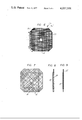
- FIG. 2 is a vertical cross section through the apparatus of FIG. 1;
- FIG. 3 is a large-scale sectional view of a portion of the apparatus of FIG. 1;
- FIG. 4a is a side view of a filter cloth in accordance with this invention.
- FIG. 4b is a side view of the support usable with the filter cloth of FIG. 4a;
- FIG. 5 is a side view partly broken away of a filter element as used in FIGS. 1-3 and employing the cloth and support of FIGS. 4a and 4b;
- FIG. 6 is a view similar to FIG. 4a showing another cloth in accordance with this invention.
- FIG. 7 shows in side view a filter element according to this invention
- FIG. 8 is a vertical section through the element of FIG. 7;
- FIG. 9 is a view similar to FIG. 8 showing another filter element according to this invention.
- FIG. 10 is a top view partly broken away of a filter element according to the present invention.
- FIG. 11 is a vertical section through the filter element of FIG. 10.
- the filter apparatus comprises a cylindrical housing 1 having a horizontal central axis A, removable cover 1' at one end and a closed opposite end 1".
- a hollow shaft 2 is rotatably supported on this housing about the axis A by a bearing 20 at the end 1" and a bearing 21 at the cover 1'.
- This shaft 2 is formed with a multiplicity of radially opening perforations 2' so that liquid can pass inwardly through these openings 2'.
- a motor 7 is mounted on the end 1" for rotation of the shaft 2 about the axis A.
- a plurality of rectangular filter elements 3 are carried on the shaft 2, each element 3 extending in a plane perpendicular to the axis A. Each of these elements 3 is spaced from the adjoining elements on the shaft 2 by means of spacer rings 19, and clips 10 carried on axially extending rods 9 ensure proper axial spacing of these elements 3.
- the rods 9 are carried on a spider 13 in a rectangular array, the spider 13 being bolted to a flange 14 on the shaft 2.
- the shaft 2 is provided with three sets of angularly equispaced arms 23 each carrying a roller 11 that engages the inside surface of the housing 1. Thus, these rollers 11 serve to rotationally support the entire assembly shown in FIG. 3 within the drum 1.
- a suspension containing particles to be filtered from a liquid is fed into the apparatus by a pump P at an inlet 4 and clear filtrate leaving the interior of the shaft 2 by the outlet 6.
- the motor 7 is not energized so that the shaft 2 stands still.
- a filter medium such as diatomaceous earth is added to the suspension to be filtered at the beginning of each filtering cycle so that it forms a filter cake on the elements 3.
- the pump P is turned off and the motor 7 is energized. This causes the filter elements 3, the shaft 2, the rods 9, and the associated structure to rotate in the housing 1 about the axis A. Simultaneously lower outlets 5 are opened on the housing and nozzles 12 connected to a manifold 8 squirt liquid between the rotating filter elements 3. This effects an extremely thorough washing-off of the filter cake on the elements 3.
- FIGS. 4a, 4b, and 5 show a filter element 3.
- This element comprises a rectangular piece 15 of filter cloth bent over so as to form a pocket in which is received a rectangular support screen 16.
- the edges 15' of the pocket are stitched tightly together and the edges 15" are closed after insertion of the screen 16 by clamping these edges between a pair or rigid bars 17 held together with screws 18. Thereafter, the entire assembly is mounted on the shaft 2 and locked in place via bolts 22 (FIG. 2).
- FIG. 6 shows a generally square filter element 3a formed with a central hole 24 like the element 3.
- This element 3a has cut-off corners 3a' which are straight and have a length 1 equal to less than one-third the length L of the longer straight side 3a" of the element 3a.
- FIGS. 7 and 8 show how such a filter element 3a is made. It is provided internally with a metal plate 18 which is square and has sides whose length is equal to less than L. This plate 18 is surrounded on both sides with support screens 16 that are then received within the pocket 15 shown in FIG. 6. In this arrangement the plate 16 is metallic, planar, and imperforate.
- FIG. 9 shows how the plate 18 can be replaced by a plate 19 that is profiled so that the screens 16 can be dispensed with and the cloth 15 can be applied directly over this plate 19.
- FIGS. 10 and 11 show an element 3b comprising an imperforate base plate 20 on the bottom, a coarse support screen 16, and a fine filter cloth 15 all of square shape. The edge is closed up on all four sides by bars 17 and screws 18 as described above. In addition a seal 21 may be provided around the screen 16 and between the cloth 15 and the base plate 20.
Landscapes
- Chemical & Material Sciences (AREA)
- Chemical Kinetics & Catalysis (AREA)
- Filtration Of Liquid (AREA)
Abstract
A filter element for a filter apparatus comprises a rigid support plate on at least one side of which is spanned a generally square filter cloth. This filter cloth may be formed as a pair of panels joined permanently together on three sides so as to form a pocket and having a fourth side which can be closed by a clamp or the like. The support is slipped into the pocket and a plurality of such filter elements are spaced along a rotatable hollow shaft centered in a filter chamber to which a solution to be filtered is fed. During operation the filtrate is pumped out of the hollow shaft through the filter cloth on which filter cake deposits. For cleaning of the cloth the shaft is rotated and the filter cake is washed off with a liquid spray.
Description
The present invention relates to a filtering apparatus. More particularly this invention concerns a filter element usable in a filtering apparatus wherein a separable suspension to be filtered is forced under pressure into the filter element.
A filtering apparatus is known having a housing defining a closed chamber in which is provided a hollow shaft carrying a plurality of axially spaced filter elements. Each of these elements comprises a support normally of porous construction and a filter cloth secured to at least one face of the support.
As a rule such supports are round so that the filter element closely fills the interior of the chamber. Such shape also facilitates rotating the filter elements during sluicing-off of filter cake that has built up on the filter elements. The filter elements in this arrangement are rotated as a liquid is squirted on them to loosen the filter cake that is then centrifugally driven off.
It is also known to have nonrotatable rectangular filter elements provided in a chamber in such manner as to be nonrotatable. With the rotatable filter elements the filtrate is drawn off through the central hollow shaft on which the rotatable elements are carried, but with the nonrotatable elements the filtrate is drawn off through channels that surround the filter surfaces.
Various prior-art filters are described in German Pat. No. 877,742, U.S. Pat. Nos. 3,107,217 and 3,190,449 as well as in the article by B. Spiekermeier and J. Stebler appearing in Maschinenmarkt on July 2, 1974 (Vogel-Verlag Wurzburg; vol. 53).
It is an object of the present invention to provide an improved filtering apparatus.
Another object is to provide an improved filter element for such an apparatus.
Yet another object is to provide an improved filter element wherein the filter cloth is used advantageously, but wherein excellent cleaning of the filter elements is possible.
These objects are attained according to the present invention in a filtering apparatus wherein a plurality of axially spaced polygonal filter supports are mounted on a hollow shaft extending axially through a closed chamber. Each of the supports has at least one face provided with a polygonal panel of filter cloth. Thus, the material constituting the filter cloth is used with maximum efficiency. At the same time excellent sluicing of the filter cake off the filter elements can be obtained.
According to yet another feature of this invention the filter cloth is formed as a pair of juxtaposed and coextensive generally square panels having three sides permanently joined together so as to form a pocket. Openable means is provided joining the other sides of the panels together and the flat stiffening member or support is provided within this pocket. Thus it is possible to make a very inexpensive filter element which can readily be changed merely by opening the one side, pulling it off, and replacing it with another whose open side is then easily closed.
In accordance with the present invention the three sides of the filter-cloth pocket may be stitched or welded together.
In accordance with yet another feature of this invention the corners of the filter-cloth panels are cut off so as to give them a generally octagonal shape and the support received in the pocket constituted by the cloth is generally square and has a maximum dimension which is equal to at most two-thirds of the maximum dimension of the pocket. Thus it is possible to slip such a filter element into one open side of the generally octagonal filter cloth.
The support may be in accordance with this invention an imperforate metal plate either formed with corrugations or other formations giving it a nonplanar shape or may be flanked by a pair of screens so that the filter can be sucked out from within the filter-cloth pocket.
The novel features which are considered as characteristic for the invention are set forth in particular in the appended claims. The invention itself, however, both as to its construction and its method of operation, together with additional objects and advantages thereof, will be best understood from the following description of specific embodiments when read in connection with the accompanying drawing.
FIG. 1 is a vertical and axial section through an apparatus according to this invention with the end cover removed;
FIG. 2 is a vertical cross section through the apparatus of FIG. 1;
FIG. 3 is a large-scale sectional view of a portion of the apparatus of FIG. 1;
FIG. 4a is a side view of a filter cloth in accordance with this invention;
FIG. 4b is a side view of the support usable with the filter cloth of FIG. 4a;
FIG. 5 is a side view partly broken away of a filter element as used in FIGS. 1-3 and employing the cloth and support of FIGS. 4a and 4b;
FIG. 6 is a view similar to FIG. 4a showing another cloth in accordance with this invention;
FIG. 7 shows in side view a filter element according to this invention;
FIG. 8 is a vertical section through the element of FIG. 7;
FIG. 9 is a view similar to FIG. 8 showing another filter element according to this invention;
FIG. 10 is a top view partly broken away of a filter element according to the present invention; and
FIG. 11 is a vertical section through the filter element of FIG. 10.
As shown in FIGS. 1-3 the filter apparatus according to the present invention comprises a cylindrical housing 1 having a horizontal central axis A, removable cover 1' at one end and a closed opposite end 1". A hollow shaft 2 is rotatably supported on this housing about the axis A by a bearing 20 at the end 1" and a bearing 21 at the cover 1'. This shaft 2 is formed with a multiplicity of radially opening perforations 2' so that liquid can pass inwardly through these openings 2'. A motor 7 is mounted on the end 1" for rotation of the shaft 2 about the axis A.
A plurality of rectangular filter elements 3 are carried on the shaft 2, each element 3 extending in a plane perpendicular to the axis A. Each of these elements 3 is spaced from the adjoining elements on the shaft 2 by means of spacer rings 19, and clips 10 carried on axially extending rods 9 ensure proper axial spacing of these elements 3. The rods 9 are carried on a spider 13 in a rectangular array, the spider 13 being bolted to a flange 14 on the shaft 2. In addition the shaft 2 is provided with three sets of angularly equispaced arms 23 each carrying a roller 11 that engages the inside surface of the housing 1. Thus, these rollers 11 serve to rotationally support the entire assembly shown in FIG. 3 within the drum 1.
During normal operation a suspension containing particles to be filtered from a liquid is fed into the apparatus by a pump P at an inlet 4 and clear filtrate leaving the interior of the shaft 2 by the outlet 6. During such operation the motor 7 is not energized so that the shaft 2 stands still. A filter medium such as diatomaceous earth is added to the suspension to be filtered at the beginning of each filtering cycle so that it forms a filter cake on the elements 3.
Once the filter cake has become too thick or is clogged the pump P is turned off and the motor 7 is energized. This causes the filter elements 3, the shaft 2, the rods 9, and the associated structure to rotate in the housing 1 about the axis A. Simultaneously lower outlets 5 are opened on the housing and nozzles 12 connected to a manifold 8 squirt liquid between the rotating filter elements 3. This effects an extremely thorough washing-off of the filter cake on the elements 3.
FIGS. 4a, 4b, and 5 show a filter element 3. This element comprises a rectangular piece 15 of filter cloth bent over so as to form a pocket in which is received a rectangular support screen 16. The edges 15' of the pocket are stitched tightly together and the edges 15" are closed after insertion of the screen 16 by clamping these edges between a pair or rigid bars 17 held together with screws 18. Thereafter, the entire assembly is mounted on the shaft 2 and locked in place via bolts 22 (FIG. 2).
FIG. 6 shows a generally square filter element 3a formed with a central hole 24 like the element 3. This element 3a has cut-off corners 3a' which are straight and have a length 1 equal to less than one-third the length L of the longer straight side 3a" of the element 3a.
FIGS. 7 and 8 show how such a filter element 3a is made. It is provided internally with a metal plate 18 which is square and has sides whose length is equal to less than L. This plate 18 is surrounded on both sides with support screens 16 that are then received within the pocket 15 shown in FIG. 6. In this arrangement the plate 16 is metallic, planar, and imperforate.
FIG. 9 shows how the plate 18 can be replaced by a plate 19 that is profiled so that the screens 16 can be dispensed with and the cloth 15 can be applied directly over this plate 19.
With the arrangement shown in FIGS. 6 and 7 it has been found possible to cut off the corners of the panel 15 as indicated by removing a triangle having a base corresponding to the edge 3a' with the length of 5 cm. This reduces the effective surface area of the filter element, equal to 200 cm2 here, by 2%. At the same time the total volume of the housing 1 can be reduced by approximately 18%, by reducing its diameter by 10 cm. This makes for a considerable saving in first cost of the apparatus.
FIGS. 10 and 11 show an element 3b comprising an imperforate base plate 20 on the bottom, a coarse support screen 16, and a fine filter cloth 15 all of square shape. The edge is closed up on all four sides by bars 17 and screws 18 as described above. In addition a seal 21 may be provided around the screen 16 and between the cloth 15 and the base plate 20.
With the system according to the present invention it is therefore possible to produce a very inexpensive filter element which can readily be cleaned. Such an arrangement has the considerable cost advantages and construction advantages of the nonrotatable types with many of the operational advantages of the rotational filter types.
It will be understood that each of the elements described above, or two or more together, may also find a useful application in other types of apparatus differing from the types described above.
While the invention has been illustrated and described as embodied in a filter apparatus, it is not intended to be limited to the details shown, since various modifications and structural changes may be made without departing in any way from the spirit of the present invention.
Without further analysis, the foregoing will so fully reveal the gist of the present invention that others can, by applying current knowledge, readily adapt it for various applications without omitting features that, from the standpoint of prior art, fairly constitute essential characteristics of the generic or specific aspects of this invention.
Claims (14)
1. A filtering apparatus comprising:
a cylindrical housing having a horizontal central axis and defining a closed chamber;
means for introducing a liquid carrying particles into said chamber;
a hollow elongated shaft in said chamber;
a plurality of laterally extending arms on said shaft provided with rollers riding on the inside of said housing;
a plurality of generally square and rigid filter supports fixed and spaced longitudinally on said shaft with same passing generally centrally through said supports;
a respective pocket of filter cloth completely and snugly surrounding each of said filter supports, each pocket being formed of a pair of juxtaposed and coextensive generally square filter-cloth panels having three sides permanently joined together and a fourth open side, said shaft passing generally centrally through said pockets;
openable means at each of said pockets joining the respective fourth sides together for forming a filter interior inside each of said pockets, said shaft opening transversely into said interiors;
means for withdrawing liquid from inside said shaft and thereby from said interiors, whereby said particles form filter cake on said panels;
means for rotating said shaft, said supports, said pockets, said arms, and said openable means jointly; and
means for spraying a rinse liquid on said pockets during rotation thereof for washing off said filter cake.
2. The apparatus defined in claim 1 wherein said openable means includes a pair of rigid bars and a plurality of screws clamping same together with said fourth sides therebetween.
3. The apparatus defined in claim 1 wherein at least two of said three sides of each pocket are welded together.
4. The apparatus defined in claim 1 wherein at least two of said three sides of each pocket are stitched together.
5. The apparatus defined in claim 1 wherein said panels have cutoff corners, whereby said pocket is generally octagonal.
6. The apparatus defined in claim 5 wherein each support is flat and has a maximum dimension equal to at least two thirds the maximum dimension of the respective panels.
7. The apparatus defined in claim 1 wherein each support is an imperforate metal plate and a pair of screens flanking the respective plate.
8. The apparatus defined in claim 7 wherein each plate is smooth and planar.
9. The apparatus defined in claim 1 wherein each support is a nonplanar imperforate metal plate.
10. The apparatus defined in claim 9 wherein said panels lie directly against the respective plate.
11. The apparatus defined in claim 1, further comprising holding rods extending generally parallel to said shaft and secured to the peripheries of said supports and said panels generally at the corners thereof.
12. The apparatus defined in claim 1, further comprising spacers between said pockets.
13. A filtering apparatus comprising:
a cylindrical housing having a horizontal central axis and defining a closed chamber;
means for introducing a liquid carrying particles into said chamber;
a hollow elongated and horizontal shaft in said chamber;
a plurality of laterally extending arms on said shaft provided with rollers riding on the inside of said housing;
a plurality of generally square and rigid upright filter plates fixed and spaced horizontally on said shaft with same passing generally centrally through said plates, each plate being fluid impervious and having two faces;
a respective generally square panel of filter cloth covering at least one face of each of said plates;
means for securing the edges of each of said panels to the edges of the respective plate and thereby forming a filter interior between each of said panels and the respective plate, said shaft passing generally centrally through said panels;
means for draining of liquid from inside said shaft and thereby from said interiors, whereby said particles form filter cake on said panels;
means for rotating said shaft, said arms, said plates, said panels, and said openable means jointly; and
means for spraying a rinse liquid on said pockets during rotation thereof for washing off said filter cake.
14. The apparatus defined in claim 13 wherein said means for introducing includes a pump for forcing said liquid carrying said particles under pressure into said chamber.
Applications Claiming Priority (4)
| Application Number | Priority Date | Filing Date | Title |
|---|---|---|---|
| CH796375A CH592464A5 (en) | 1975-06-17 | 1975-06-17 | Filter for liqs. - with square filter elements mounted on hollow shaft in a vessel |
| CH7963/75 | 1975-06-17 | ||
| CH9208/75 | 1975-07-11 | ||
| CH920875A CH603212A5 (en) | 1975-07-11 | 1975-07-11 | Filter for liqs. |
Publications (1)
| Publication Number | Publication Date |
|---|---|
| US4057501A true US4057501A (en) | 1977-11-08 |
Family
ID=25702523
Family Applications (1)
| Application Number | Title | Priority Date | Filing Date |
|---|---|---|---|
| US05/694,196 Expired - Lifetime US4057501A (en) | 1975-06-17 | 1976-06-09 | Filter apparatus and filter element therefor |
Country Status (3)
| Country | Link |
|---|---|
| US (1) | US4057501A (en) |
| JP (1) | JPS5228065A (en) |
| DE (1) | DE2625594A1 (en) |
Cited By (4)
| Publication number | Priority date | Publication date | Assignee | Title |
|---|---|---|---|---|
| US4919805A (en) * | 1986-11-26 | 1990-04-24 | Johnson Willard L | Vertical leaf filter flush |
| US5093000A (en) * | 1989-10-25 | 1992-03-03 | Esmil Water Systems Bv | Filtration apparatus |
| US5639369A (en) * | 1995-07-14 | 1997-06-17 | W. L. Gore & Associates, Inc. | Filter element |
| US5720878A (en) * | 1996-03-07 | 1998-02-24 | Chem-Nuclear Systems, Inc. | Panel filter system |
Families Citing this family (2)
| Publication number | Priority date | Publication date | Assignee | Title |
|---|---|---|---|---|
| DE3141519C2 (en) * | 1981-10-20 | 1984-11-22 | Salzgitter Maschinen- und Anlagen AG, 3320 Salzgitter | Precoat filter for the ultra-fine filtration of liquids |
| DE3339177A1 (en) * | 1982-11-25 | 1984-07-05 | Passavant-Werke AG & Co KG, 6209 Aarbergen | Process and device for purifying waste water or treating utility water |
Citations (11)
| Publication number | Priority date | Publication date | Assignee | Title |
|---|---|---|---|---|
| US925554A (en) * | 1907-11-16 | 1909-06-22 | Hiram W Blaisdell | Filter-leaf. |
| GB384749A (en) * | 1931-10-26 | 1932-12-15 | Charles Mcneil | Improvements in or relating to filters |
| US2540362A (en) * | 1947-04-16 | 1951-02-06 | Fred H Winslow | Filter |
| US2544402A (en) * | 1947-11-15 | 1951-03-06 | Arnold Jacobowitz | Liquid filter |
| GB655623A (en) * | 1947-01-27 | 1951-07-25 | Luigi Bordiga | Improvements in or relating to filtration apparatus |
| US2772000A (en) * | 1953-03-30 | 1956-11-27 | Charles E Hunziker | Leaf anchoring means |
| US2878942A (en) * | 1955-07-13 | 1959-03-24 | Horace B Whitmore | Filter unit |
| US3161592A (en) * | 1962-12-28 | 1964-12-15 | Suchar Sales Corp | Filter discharge apparatus |
| US3190449A (en) * | 1956-06-11 | 1965-06-22 | Hans Mueller | Filter apparatus |
| US3263819A (en) * | 1963-06-19 | 1966-08-02 | Multi Metal Wire Cloth Company | Filter leaf structure |
| US3655049A (en) * | 1970-11-19 | 1972-04-11 | Sparkler Mfg Co | Method and apparatus for retaining and dislodging filter cake |
-
1976
- 1976-06-08 DE DE19762625594 patent/DE2625594A1/en not_active Withdrawn
- 1976-06-09 US US05/694,196 patent/US4057501A/en not_active Expired - Lifetime
- 1976-06-17 JP JP51071658A patent/JPS5228065A/en active Pending
Patent Citations (11)
| Publication number | Priority date | Publication date | Assignee | Title |
|---|---|---|---|---|
| US925554A (en) * | 1907-11-16 | 1909-06-22 | Hiram W Blaisdell | Filter-leaf. |
| GB384749A (en) * | 1931-10-26 | 1932-12-15 | Charles Mcneil | Improvements in or relating to filters |
| GB655623A (en) * | 1947-01-27 | 1951-07-25 | Luigi Bordiga | Improvements in or relating to filtration apparatus |
| US2540362A (en) * | 1947-04-16 | 1951-02-06 | Fred H Winslow | Filter |
| US2544402A (en) * | 1947-11-15 | 1951-03-06 | Arnold Jacobowitz | Liquid filter |
| US2772000A (en) * | 1953-03-30 | 1956-11-27 | Charles E Hunziker | Leaf anchoring means |
| US2878942A (en) * | 1955-07-13 | 1959-03-24 | Horace B Whitmore | Filter unit |
| US3190449A (en) * | 1956-06-11 | 1965-06-22 | Hans Mueller | Filter apparatus |
| US3161592A (en) * | 1962-12-28 | 1964-12-15 | Suchar Sales Corp | Filter discharge apparatus |
| US3263819A (en) * | 1963-06-19 | 1966-08-02 | Multi Metal Wire Cloth Company | Filter leaf structure |
| US3655049A (en) * | 1970-11-19 | 1972-04-11 | Sparkler Mfg Co | Method and apparatus for retaining and dislodging filter cake |
Cited By (4)
| Publication number | Priority date | Publication date | Assignee | Title |
|---|---|---|---|---|
| US4919805A (en) * | 1986-11-26 | 1990-04-24 | Johnson Willard L | Vertical leaf filter flush |
| US5093000A (en) * | 1989-10-25 | 1992-03-03 | Esmil Water Systems Bv | Filtration apparatus |
| US5639369A (en) * | 1995-07-14 | 1997-06-17 | W. L. Gore & Associates, Inc. | Filter element |
| US5720878A (en) * | 1996-03-07 | 1998-02-24 | Chem-Nuclear Systems, Inc. | Panel filter system |
Also Published As
| Publication number | Publication date |
|---|---|
| DE2625594A1 (en) | 1977-01-13 |
| JPS5228065A (en) | 1977-03-02 |
Similar Documents
| Publication | Publication Date | Title |
|---|---|---|
| US2221210A (en) | Filter for dry cleaner solvents | |
| US4379051A (en) | Filtering apparatus | |
| US4957630A (en) | Drum filter with divergent hole perforated filter media | |
| US4057501A (en) | Filter apparatus and filter element therefor | |
| US3731814A (en) | Liquid filter | |
| US3884813A (en) | Solids concentrator with a rotor having ploughs thereon | |
| US4944874A (en) | Centrifugal separator | |
| US4551248A (en) | Filter drum for rotary drum vacuum filter | |
| US3542205A (en) | Filter leaf | |
| US920739A (en) | Metallurgical filter. | |
| US4722789A (en) | Chamber filter press with rotor plates | |
| US399984A (en) | Dust-collector | |
| US3286843A (en) | Self-cleaning filter | |
| US3491889A (en) | Liquid filter | |
| US2253692A (en) | Filter construction | |
| US2744632A (en) | Filtering screen assembly | |
| US1685085A (en) | Dewatering apparatus | |
| US3045409A (en) | Air filter for dust collector | |
| US3695447A (en) | Self-cleaning filter, particularly for dry-cleaning plants | |
| US3438497A (en) | Method and apparatus for the automatic cleansing of the filter for a solvent,particularly in dry-cleaning plants | |
| US3356219A (en) | Filter element precoat removal means | |
| US3935107A (en) | Filter | |
| US3655049A (en) | Method and apparatus for retaining and dislodging filter cake | |
| US1293555A (en) | Filter leaf or disk. | |
| US3950254A (en) | Solids concentrator with a rotor having ploughs thereon |
Legal Events
| Date | Code | Title | Description |
|---|---|---|---|
| AS | Assignment |
Owner name: CHEMAP AG Free format text: ASSIGNMENT OF ASSIGNORS INTEREST.;ASSIGNOR:MULLER, HANS;REEL/FRAME:004117/0791 Effective date: 19830318 |