US4046402A - Ball joint suspension for a motor vehicle - Google Patents
Ball joint suspension for a motor vehicle Download PDFInfo
- Publication number
- US4046402A US4046402A US05/593,802 US59380275A US4046402A US 4046402 A US4046402 A US 4046402A US 59380275 A US59380275 A US 59380275A US 4046402 A US4046402 A US 4046402A
- Authority
- US
- United States
- Prior art keywords
- loop
- wheel
- vehicle frame
- positioning member
- socket
- Prior art date
- Legal status (The legal status is an assumption and is not a legal conclusion. Google has not performed a legal analysis and makes no representation as to the accuracy of the status listed.)
- Expired - Lifetime
Links
- 239000000725 suspension Substances 0.000 title claims abstract description 24
- 238000010276 construction Methods 0.000 claims description 5
- 230000003014 reinforcing effect Effects 0.000 claims 4
- 239000006096 absorbing agent Substances 0.000 description 2
- 238000004519 manufacturing process Methods 0.000 description 2
- 239000002184 metal Substances 0.000 description 2
- 230000035939 shock Effects 0.000 description 2
- 230000004075 alteration Effects 0.000 description 1
- 230000004048 modification Effects 0.000 description 1
- 238000012986 modification Methods 0.000 description 1
- 239000003381 stabilizer Substances 0.000 description 1
Images
Classifications
-
- B—PERFORMING OPERATIONS; TRANSPORTING
- B60—VEHICLES IN GENERAL
- B60G—VEHICLE SUSPENSION ARRANGEMENTS
- B60G21/00—Interconnection systems for two or more resiliently-suspended wheels, e.g. for stabilising a vehicle body with respect to acceleration, deceleration or centrifugal forces
- B60G21/02—Interconnection systems for two or more resiliently-suspended wheels, e.g. for stabilising a vehicle body with respect to acceleration, deceleration or centrifugal forces permanently interconnected
- B60G21/04—Interconnection systems for two or more resiliently-suspended wheels, e.g. for stabilising a vehicle body with respect to acceleration, deceleration or centrifugal forces permanently interconnected mechanically
- B60G21/05—Interconnection systems for two or more resiliently-suspended wheels, e.g. for stabilising a vehicle body with respect to acceleration, deceleration or centrifugal forces permanently interconnected mechanically between wheels on the same axle but on different sides of the vehicle, i.e. the left and right wheel suspensions being interconnected
- B60G21/055—Stabiliser bars
- B60G21/0551—Mounting means therefor
-
- B—PERFORMING OPERATIONS; TRANSPORTING
- B60—VEHICLES IN GENERAL
- B60G—VEHICLE SUSPENSION ARRANGEMENTS
- B60G11/00—Resilient suspensions characterised by arrangement, location or kind of springs
- B60G11/18—Resilient suspensions characterised by arrangement, location or kind of springs having torsion-bar springs only
- B60G11/20—Resilient suspensions characterised by arrangement, location or kind of springs having torsion-bar springs only characterised by means specially adapted for attaching the spring to axle or sprung part of the vehicle
-
- B—PERFORMING OPERATIONS; TRANSPORTING
- B60—VEHICLES IN GENERAL
- B60G—VEHICLE SUSPENSION ARRANGEMENTS
- B60G15/00—Resilient suspensions characterised by arrangement, location or type of combined spring and vibration damper, e.g. telescopic type
- B60G15/02—Resilient suspensions characterised by arrangement, location or type of combined spring and vibration damper, e.g. telescopic type having mechanical spring
- B60G15/06—Resilient suspensions characterised by arrangement, location or type of combined spring and vibration damper, e.g. telescopic type having mechanical spring and fluid damper
-
- B—PERFORMING OPERATIONS; TRANSPORTING
- B60—VEHICLES IN GENERAL
- B60G—VEHICLE SUSPENSION ARRANGEMENTS
- B60G7/00—Pivoted suspension arms; Accessories thereof
- B60G7/001—Suspension arms, e.g. constructional features
-
- B—PERFORMING OPERATIONS; TRANSPORTING
- B60—VEHICLES IN GENERAL
- B60G—VEHICLE SUSPENSION ARRANGEMENTS
- B60G7/00—Pivoted suspension arms; Accessories thereof
- B60G7/005—Ball joints
-
- B—PERFORMING OPERATIONS; TRANSPORTING
- B60—VEHICLES IN GENERAL
- B60G—VEHICLE SUSPENSION ARRANGEMENTS
- B60G2202/00—Indexing codes relating to the type of spring, damper or actuator
- B60G2202/10—Type of spring
- B60G2202/13—Torsion spring
-
- B—PERFORMING OPERATIONS; TRANSPORTING
- B60—VEHICLES IN GENERAL
- B60G—VEHICLE SUSPENSION ARRANGEMENTS
- B60G2204/00—Indexing codes related to suspensions per se or to auxiliary parts
- B60G2204/10—Mounting of suspension elements
- B60G2204/12—Mounting of springs or dampers
- B60G2204/122—Mounting of torsion springs
-
- B—PERFORMING OPERATIONS; TRANSPORTING
- B60—VEHICLES IN GENERAL
- B60G—VEHICLE SUSPENSION ARRANGEMENTS
- B60G2206/00—Indexing codes related to the manufacturing of suspensions: constructional features, the materials used, procedures or tools
- B60G2206/01—Constructional features of suspension elements, e.g. arms, dampers, springs
- B60G2206/10—Constructional features of arms
- B60G2206/124—Constructional features of arms the arm having triangular or Y-shape, e.g. wishbone
-
- B—PERFORMING OPERATIONS; TRANSPORTING
- B60—VEHICLES IN GENERAL
- B60G—VEHICLE SUSPENSION ARRANGEMENTS
- B60G2206/00—Indexing codes related to the manufacturing of suspensions: constructional features, the materials used, procedures or tools
- B60G2206/01—Constructional features of suspension elements, e.g. arms, dampers, springs
- B60G2206/40—Constructional features of dampers and/or springs
- B60G2206/42—Springs
-
- B—PERFORMING OPERATIONS; TRANSPORTING
- B60—VEHICLES IN GENERAL
- B60G—VEHICLE SUSPENSION ARRANGEMENTS
- B60G2206/00—Indexing codes related to the manufacturing of suspensions: constructional features, the materials used, procedures or tools
- B60G2206/01—Constructional features of suspension elements, e.g. arms, dampers, springs
- B60G2206/70—Materials used in suspensions
- B60G2206/72—Steel
- B60G2206/724—Wires, bars or the like
Definitions
- the present invention relates to independent front suspension systems for motor vehicles, and more particularly to ball joint suspensions.
- a torsion bar spring has a wheel positioning portion that functions as a suspension arm and a ball joint connects that bar portion to a wheel support member.
- an independent front suspension system for a motor vehicle has a single continuous torsion bar spring that is formed into the shape of a closed figure.
- the bar has first and second transverse portions that are situated fore and aft the axis of rotation of the left and right front wheels.
- the torsion bar has single loops or coils at each of the ends of the transverse portions and these loops are connected to the vehicle frame by resilient devices.
- a generally Y-shape torsion bar portion connects the loops at the right ends of the transverse bar portions with the right wheel support member.
- a generally Y-shape left bar portion connects the bar loops at the left ends of the transverse portions with the left wheel support member.
- the left and right Y-shape portions of the torsion bar constitute wheel positioning members in the suspension system.
- the left and right outer ends of the torsion bar spring are each formed with a small loop.
- the sockets of left and right ball joints are press-fitted into these loops.
- the shank of the ball stud portions of the joints are secured to the left and right wheel support members.
- left and right telescopic shock absorbers have their lower ends rigidly secured to the wheel support members and their upper ends connected to vehicle body structure.
- An independent suspension system for a motor vehicle in accordance with this invention is characterized by its simplicity of construction and economy of manufacture. It is particularly well suited to light-weight vehicles.
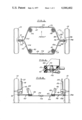
- FIG. 1 is a top plan view of an independent suspension system for a motor vehicle
- FIG. 2 is a rear elevational view of the vehicle suspension of FIG. 1;
- FIG. 3 is a side elevational view of the left side of the suspension of FIG. 1;
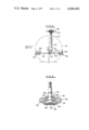
- FIG. 4 is a sectional view, taken along section line 4--4 of FIG. 1, disclosing the connection between the torsion bar spring and the vehicle frame;
- FIG. 5 is a sectional view of the ball joint connecting the torsion bar spring to the wheel support member of the suspension system.
- left and right road wheels 10 and 12 are rotatably supported on left and right wheel support members 14 and 16.
- Left and right telescopic shock absorbers or suspension struts 18 and 20 have their lower ends rigidly secured to the wheel support members 14 and 16.
- Piston rods 22 and 24 extend upwardly from the struts 18 and 20.
- the upper end of the piston rod 22 is secured to vehicle body structure 26 by means of a resilient connector 28.
- the piston rod 24 is connected to the vehicle body structure in a similar manner.
- a continuous torsion bar spring 30 that is formed into the shape of a closed figure is connected to the vehicle body and to the left and right wheel support members 14 and 16.
- the torsion bar 30 has transverse portions 32 and 34 that are spaced fore and aft, respectively, of the axis of rotation of the wheels 10 and 12.
- the torsion bar 30 is provided with a single loop or coil at each of the outer ends of the transverse bar portions 32 and 34.
- Single coils 36 and 38 are located at the outer ends of the forward transverse portion 32 and single coils 40 and 42 are located at the left and right ends of the rearward transverse portion 34.
- Each of the coils 36, 38, 40 and 42 is connected to the vehicle body.
- the vehicle body structure includes left and right frame side rails 44 and 46. Resilient means are provided for connecting the left coils 36 and 40 to the left frame rail 44. Similarly, a resilient means is provided to connect each of the right torsion bar coils 38 and 42 to the right frame side rail 46. The construction of one of these resilient connections is shown in FIG. 4.
- a spring seat 48 is welded to the right frame side rail 46 and has a frusto-conical portion 50.
- An annular rubber element 52 is positioned within the center of the coil 42 and has a circumferential groove to receive the coil. The rubber element 52 engages the spring seat 48 and its frusto-conical wall 50.
- a sheet metal retaining plate 54 having a configuration as shown in the drawings, engages the rubber element 52 and is secured to the spring seat 48 by a bolt 56.
- the left frame side rail 44 has fore and aft spring seats 58 and 60 welded to it that are constructed similar to the spring seat 48 of FIG. 4.
- the fore and aft loops 36 and 40 of the torsion bar 30 are secured to the spring seats 58 and 60 by resilient devices of the type shown in FIG. 4.
- a generally Y-shape portion 62 of the bar 30 connects the fore and aft spring loops 36 and 40 to the left wheel support member 14.
- the Y-shape portion 62 has a forward diagonally arranged strut portion 64 and a rearward diagonally arranged strut portion 66.
- the left extremity of the bar 30 has parallel portions 68 and 70 connected to the strut portions 64 and 66 which terminate in a small loop 72.
- a ball and socket joint 74 connects the small loop 72 at the left end of the bar 30 to the left wheel support member 14.
- the joint 74 includes a socket portion 76 in which an annular bearing 78 is pivotally supported.
- the shank 80 of a stud 82 extends through an opening 84 in the socket 76.
- the head 86 of the stud 82 rests against the bearing 78.
- the shank 80 of the stud 82 is constructed to be secured to the wheel support member 14.
- the interior of the socket 76 is closed by a closure plate 88 that is engaged by a crimped over edge of the socket.
- the ball joint socket 76 has a ledge or radially extending flange 90 that protrudes from its lower end outwardly of the closure plate 88. Spaced upwardly from the flange 90 is an annular recess 92.
- the ball joint assembly 78 is forced through the loop 72 in the torsion bar spring 30 until it engages the ledge 90 and is seated in the recess 92.
- the ball joint socket 76 is held in place by a press fit.
- the prevailing forces exerted by the bar 30 in its function as a main suspension spring are in a downward direction against the ledge 90 and, therefore, the ball joint assembly 74 is held securely against accidental dislodgement.
- a metal band 94 may be strapped around the laterally extending portions 68 and 70 of the torsion bar 30 adjacent to the socket 76. The band 94 reinforces the loop 72 in its gripping engagement with the socket 76.
- a generally Y-shape portion 96 of the torsion bar 30 has diagonal strut portions 98 and 100 connected to the fore and aft spring loops 38 and 42.
- the Y-shape portion 96 at the right side of the spring 30, has laterally extending portions 102 and 104 which terminate in a small loop 106.
- the socket of the ball joint assembly 108 is press-fitted into the loop 106.
- a strap 110 serves to lock the ball joint 108 in position.
- the ball joint assembly 108 provides an articulated connection between the torsion bar 30 and the right wheel support member 16.
- the spring 30 may be fabricated in left and right halves as illustrated in FIG. 1. These spring halves are identical and interchangeable. The spring halves have ends that are fitted into fore and aft sleeves 112 and 114 where they are welded securely in place so that the torsion bar 30 is fabricated to form a single continuous spring bar of closed configuration.
- the torsion bar spring 30 is a single continuous spring formed in the shape of a closed figure that interconnects the left and right wheel support members 14, 16 and is supported on the vehicle frame 44, 46 at four spaced apart points.
- the torsion bar 30 functions as a main suspension spring, as left and right suspension arms for positioning the wheel support members and as an anti-roll stabilizer.
- the left and right portions 62 and 96 of the bar 30 which form the suspension arms are securely locked to the left and right ball joints 72 and 108 by means of press fits.
Landscapes
- Engineering & Computer Science (AREA)
- Mechanical Engineering (AREA)
- Vehicle Body Suspensions (AREA)
Abstract
A ball joint suspension for a motor vehicle is disclosed. A torsion bar spring has laterally extending left and right wheel positioning portions of generally Y-shape. The outer ends of these portions each comprise parallel bars that are interconnected by a small loop. A ball joint has its socket press-fitted into the small loop and its ball stud secured to a wheel support member.
Description
The present invention relates to independent front suspension systems for motor vehicles, and more particularly to ball joint suspensions. In accordance with the present disclosure a torsion bar spring has a wheel positioning portion that functions as a suspension arm and a ball joint connects that bar portion to a wheel support member.
In a presently preferred embodiment of this invention, an independent front suspension system for a motor vehicle has a single continuous torsion bar spring that is formed into the shape of a closed figure. The bar has first and second transverse portions that are situated fore and aft the axis of rotation of the left and right front wheels. The torsion bar has single loops or coils at each of the ends of the transverse portions and these loops are connected to the vehicle frame by resilient devices.
A generally Y-shape torsion bar portion connects the loops at the right ends of the transverse bar portions with the right wheel support member. In a similar fashion, a generally Y-shape left bar portion connects the bar loops at the left ends of the transverse portions with the left wheel support member. The left and right Y-shape portions of the torsion bar constitute wheel positioning members in the suspension system.
The left and right outer ends of the torsion bar spring are each formed with a small loop. The sockets of left and right ball joints are press-fitted into these loops. The shank of the ball stud portions of the joints are secured to the left and right wheel support members.
In the illustrated embodiment of the invention, left and right telescopic shock absorbers have their lower ends rigidly secured to the wheel support members and their upper ends connected to vehicle body structure.
An independent suspension system for a motor vehicle in accordance with this invention is characterized by its simplicity of construction and economy of manufacture. It is particularly well suited to light-weight vehicles.
The many objects and advantages of an independent suspension system for a motor vehicle constructed in accordance with this invention will become apparent upon consideration of the following detailed discussion and the accompanying drawings, in which:
FIG. 1 is a top plan view of an independent suspension system for a motor vehicle;
FIG. 2 is a rear elevational view of the vehicle suspension of FIG. 1;
FIG. 3 is a side elevational view of the left side of the suspension of FIG. 1;
FIG. 4 is a sectional view, taken along section line 4--4 of FIG. 1, disclosing the connection between the torsion bar spring and the vehicle frame; and
FIG. 5 is a sectional view of the ball joint connecting the torsion bar spring to the wheel support member of the suspension system.
Referring now to the drawings, wherein a preferred embodiment of an independent front suspension system for a motor vehicle is disclosed, left and right road wheels 10 and 12 are rotatably supported on left and right wheel support members 14 and 16. Left and right telescopic shock absorbers or suspension struts 18 and 20 have their lower ends rigidly secured to the wheel support members 14 and 16. Piston rods 22 and 24 extend upwardly from the struts 18 and 20. As seen in FIG. 3, the upper end of the piston rod 22 is secured to vehicle body structure 26 by means of a resilient connector 28. The piston rod 24 is connected to the vehicle body structure in a similar manner.
A continuous torsion bar spring 30 that is formed into the shape of a closed figure is connected to the vehicle body and to the left and right wheel support members 14 and 16. The torsion bar 30 has transverse portions 32 and 34 that are spaced fore and aft, respectively, of the axis of rotation of the wheels 10 and 12. The torsion bar 30 is provided with a single loop or coil at each of the outer ends of the transverse bar portions 32 and 34. Single coils 36 and 38 are located at the outer ends of the forward transverse portion 32 and single coils 40 and 42 are located at the left and right ends of the rearward transverse portion 34.
Each of the coils 36, 38, 40 and 42 is connected to the vehicle body. The vehicle body structure includes left and right frame side rails 44 and 46. Resilient means are provided for connecting the left coils 36 and 40 to the left frame rail 44. Similarly, a resilient means is provided to connect each of the right torsion bar coils 38 and 42 to the right frame side rail 46. The construction of one of these resilient connections is shown in FIG. 4.
A spring seat 48 is welded to the right frame side rail 46 and has a frusto-conical portion 50. An annular rubber element 52 is positioned within the center of the coil 42 and has a circumferential groove to receive the coil. The rubber element 52 engages the spring seat 48 and its frusto-conical wall 50. A sheet metal retaining plate 54, having a configuration as shown in the drawings, engages the rubber element 52 and is secured to the spring seat 48 by a bolt 56.
The left frame side rail 44 has fore and aft spring seats 58 and 60 welded to it that are constructed similar to the spring seat 48 of FIG. 4. The fore and aft loops 36 and 40 of the torsion bar 30 are secured to the spring seats 58 and 60 by resilient devices of the type shown in FIG. 4.
A generally Y-shape portion 62 of the bar 30 connects the fore and aft spring loops 36 and 40 to the left wheel support member 14. The Y-shape portion 62 has a forward diagonally arranged strut portion 64 and a rearward diagonally arranged strut portion 66. The left extremity of the bar 30 has parallel portions 68 and 70 connected to the strut portions 64 and 66 which terminate in a small loop 72.
A ball and socket joint 74 connects the small loop 72 at the left end of the bar 30 to the left wheel support member 14. The joint 74 includes a socket portion 76 in which an annular bearing 78 is pivotally supported. The shank 80 of a stud 82 extends through an opening 84 in the socket 76. The head 86 of the stud 82 rests against the bearing 78. The shank 80 of the stud 82 is constructed to be secured to the wheel support member 14. The interior of the socket 76 is closed by a closure plate 88 that is engaged by a crimped over edge of the socket.
The ball joint socket 76 has a ledge or radially extending flange 90 that protrudes from its lower end outwardly of the closure plate 88. Spaced upwardly from the flange 90 is an annular recess 92. The ball joint assembly 78 is forced through the loop 72 in the torsion bar spring 30 until it engages the ledge 90 and is seated in the recess 92. The ball joint socket 76 is held in place by a press fit. The prevailing forces exerted by the bar 30 in its function as a main suspension spring are in a downward direction against the ledge 90 and, therefore, the ball joint assembly 74 is held securely against accidental dislodgement. As an additional securing feature, a metal band 94 (see FIG. 1) may be strapped around the laterally extending portions 68 and 70 of the torsion bar 30 adjacent to the socket 76. The band 94 reinforces the loop 72 in its gripping engagement with the socket 76.
In a similar fashion, a generally Y-shape portion 96 of the torsion bar 30 has diagonal strut portions 98 and 100 connected to the fore and aft spring loops 38 and 42. The Y-shape portion 96, at the right side of the spring 30, has laterally extending portions 102 and 104 which terminate in a small loop 106. The socket of the ball joint assembly 108 is press-fitted into the loop 106. A strap 110 serves to lock the ball joint 108 in position. The ball joint assembly 108 provides an articulated connection between the torsion bar 30 and the right wheel support member 16.
The spring 30 may be fabricated in left and right halves as illustrated in FIG. 1. These spring halves are identical and interchangeable. The spring halves have ends that are fitted into fore and aft sleeves 112 and 114 where they are welded securely in place so that the torsion bar 30 is fabricated to form a single continuous spring bar of closed configuration.
An independent front suspension system in accordance with this invention is of uncomplicated construction and is economical to manufacture. The torsion bar spring 30 is a single continuous spring formed in the shape of a closed figure that interconnects the left and right wheel support members 14, 16 and is supported on the vehicle frame 44, 46 at four spaced apart points. The torsion bar 30 functions as a main suspension spring, as left and right suspension arms for positioning the wheel support members and as an anti-roll stabilizer. In a unique manner, the left and right portions 62 and 96 of the bar 30 which form the suspension arms are securely locked to the left and right ball joints 72 and 108 by means of press fits.
The foregoing description presents the presently preferred embodiment of this invention. Modifications and alterations may occur to those skilled in the art that will come within the scope and spirit of the following claims.
Claims (4)
1. A ball joint suspension for a motor vehicle having a vehicle frame;
a wheel positioning member connected to said vehicle frame;
a wheel support member constructed to rotatably support a road wheel;
said wheel positioning member having fore and aft branch portions connected to said vehicle frame and a laterally extending portion comprising parallel rods that are interconnected at their outer ends by a loop;
said loop defining a small opening in which the socket of a ball joint is secured by a press fit;
reinforcing means engaging said parallel rods adjacent said loop;
said joint having a stud connected to said wheel support member.
2. A ball joint suspension for a motor vehicle having a vehicle frame;
a wheel positioning member connected to said vehicle frame;
a wheel support member constructed to rotatably support a road wheel;
said wheel positioning member having fore and aft branch portions connected to said vehicle frame and a laterally extending portion comprising parallel rods that are interconnected at their outer ends by a loop,
said loop defining a small opening in which the socket of a ball joint is secured by a press fit;
said socket having a ledge portion in engagement with said loop;
reinforcing means engaging said parallel rods adjacent said loop;
said joint having a stud connected to said wheel support member.
3. A ball joint suspension for a motor vehicle having a vehicle frame;
a road wheel rotatably supported by a wheel support member;
a wheel positioning member connected to said vehicle frame;
said wheel positioning member comprising a rodlike construction with a generally Y-shape;
said wheel positioning member having fore and aft strut portions connected to said vehicle frame;
said wheel positioning member having a laterally extending portion comprising parallel rods that are interconnected at their outer ends by an integral loop;
said loop defining a small opening;
a ball and socket joint having a socket positioned in said opening and in press fit engagement with said loop;
reinforcing means engaging said parallel rods adjacent said loop;
said joint having a stud connected to said wheel support member.
4. A ball joint suspension for a motor vehicle having a vehicle frame;
a road wheel rotatably supported by a wheel support member;
a wheel positioning member connected to said vehicle frame;
said wheel positioning member comprising a rod-like construction with a generally Y-shape;
said wheel positioning member having fore and aft strut portions connected to said vehicle frame;
said wheel positioning member having a laterally extending portion comprising parallel rods that are interconnected at their outer ends by an integral loop;
said loop defining a small opening;
a ball and socket joint having a socket positioned in said opening and in press fit engagement with said loop;
said socket having an annular exterior recess and a ledge spaced from said recess;
said loop being seated in said recess and in engagement with said ledge;
reinforcing means engaging said parallel rods adjacent said loop;
said joint having a stud connected to said wheel support member.
Priority Applications (3)
| Application Number | Priority Date | Filing Date | Title |
|---|---|---|---|
| US05/593,802 US4046402A (en) | 1975-07-07 | 1975-07-07 | Ball joint suspension for a motor vehicle |
| CA253,308A CA1051043A (en) | 1975-07-07 | 1976-05-26 | Ball joint suspension for a motor vehicle |
| GB27139/76A GB1493216A (en) | 1975-07-07 | 1976-06-30 | Suspension for a motor vehicle |
Applications Claiming Priority (1)
| Application Number | Priority Date | Filing Date | Title |
|---|---|---|---|
| US05/593,802 US4046402A (en) | 1975-07-07 | 1975-07-07 | Ball joint suspension for a motor vehicle |
Publications (1)
| Publication Number | Publication Date |
|---|---|
| US4046402A true US4046402A (en) | 1977-09-06 |
Family
ID=24376249
Family Applications (1)
| Application Number | Title | Priority Date | Filing Date |
|---|---|---|---|
| US05/593,802 Expired - Lifetime US4046402A (en) | 1975-07-07 | 1975-07-07 | Ball joint suspension for a motor vehicle |
Country Status (3)
| Country | Link |
|---|---|
| US (1) | US4046402A (en) |
| CA (1) | CA1051043A (en) |
| GB (1) | GB1493216A (en) |
Cited By (5)
| Publication number | Priority date | Publication date | Assignee | Title |
|---|---|---|---|---|
| US4134604A (en) * | 1977-07-07 | 1979-01-16 | Jackson Lift Co., Inc. | Vehicle suspension |
| EP0963865A1 (en) * | 1998-06-10 | 1999-12-15 | Automobiles Peugeot | Manufacturing method of a metallic suspension triangle, triangle obtained by this method and mold for this method |
| US6176502B1 (en) * | 1998-04-22 | 2001-01-23 | Compagnie Generale Des Etablissements Michelin-Michelin & Cie | Torsion axle |
| CN106985629A (en) * | 2017-05-15 | 2017-07-28 | 徐州徐工矿山机械有限公司 | A type frame structure before a kind of articulator |
| US20230128477A1 (en) * | 2019-12-27 | 2023-04-27 | Iljin Co., Ltd. | Vehicle suspension arm |
Citations (11)
| Publication number | Priority date | Publication date | Assignee | Title |
|---|---|---|---|---|
| US377817A (en) * | 1888-02-14 | Vehicle-spring | ||
| US2856198A (en) * | 1956-03-07 | 1958-10-14 | Ford Motor Co | Motor vehicle wheel suspension |
| US2915321A (en) * | 1953-07-02 | 1959-12-01 | Daimler Benz Ag | Torsion rod spring system for vehicles especially motor vehicles |
| FR1241657A (en) * | 1958-12-03 | 1960-09-16 | Ehrenreich & Co A | Device for supporting or suspending the joints of vehicle wheels |
| GB895475A (en) * | 1959-11-16 | 1962-05-02 | Ford Motor Co | Improvements in or relating to motor vehicle suspensions |
| GB987670A (en) * | 1964-03-16 | 1965-03-31 | Ford Motor Co | Motor vehicle independent suspension |
| US3620548A (en) * | 1968-03-30 | 1971-11-16 | Friedrich H Van Winsen | Suspension of steerable front wheels of motor vehicles |
| US3650540A (en) * | 1970-02-06 | 1972-03-21 | Donald J Verley | Vehicle suspension system |
| US3658312A (en) * | 1970-04-13 | 1972-04-25 | Moog Industries Inc | Vehicle torsion spring suspension assembly |
| US3726539A (en) * | 1969-07-25 | 1973-04-10 | Girling Ltd | Vehicle suspension units |
| US3850443A (en) * | 1973-06-04 | 1974-11-26 | Chrysler Corp | Ball joint |
-
1975
- 1975-07-07 US US05/593,802 patent/US4046402A/en not_active Expired - Lifetime
-
1976
- 1976-05-26 CA CA253,308A patent/CA1051043A/en not_active Expired
- 1976-06-30 GB GB27139/76A patent/GB1493216A/en not_active Expired
Patent Citations (11)
| Publication number | Priority date | Publication date | Assignee | Title |
|---|---|---|---|---|
| US377817A (en) * | 1888-02-14 | Vehicle-spring | ||
| US2915321A (en) * | 1953-07-02 | 1959-12-01 | Daimler Benz Ag | Torsion rod spring system for vehicles especially motor vehicles |
| US2856198A (en) * | 1956-03-07 | 1958-10-14 | Ford Motor Co | Motor vehicle wheel suspension |
| FR1241657A (en) * | 1958-12-03 | 1960-09-16 | Ehrenreich & Co A | Device for supporting or suspending the joints of vehicle wheels |
| GB895475A (en) * | 1959-11-16 | 1962-05-02 | Ford Motor Co | Improvements in or relating to motor vehicle suspensions |
| GB987670A (en) * | 1964-03-16 | 1965-03-31 | Ford Motor Co | Motor vehicle independent suspension |
| US3620548A (en) * | 1968-03-30 | 1971-11-16 | Friedrich H Van Winsen | Suspension of steerable front wheels of motor vehicles |
| US3726539A (en) * | 1969-07-25 | 1973-04-10 | Girling Ltd | Vehicle suspension units |
| US3650540A (en) * | 1970-02-06 | 1972-03-21 | Donald J Verley | Vehicle suspension system |
| US3658312A (en) * | 1970-04-13 | 1972-04-25 | Moog Industries Inc | Vehicle torsion spring suspension assembly |
| US3850443A (en) * | 1973-06-04 | 1974-11-26 | Chrysler Corp | Ball joint |
Cited By (6)
| Publication number | Priority date | Publication date | Assignee | Title |
|---|---|---|---|---|
| US4134604A (en) * | 1977-07-07 | 1979-01-16 | Jackson Lift Co., Inc. | Vehicle suspension |
| US6176502B1 (en) * | 1998-04-22 | 2001-01-23 | Compagnie Generale Des Etablissements Michelin-Michelin & Cie | Torsion axle |
| EP0963865A1 (en) * | 1998-06-10 | 1999-12-15 | Automobiles Peugeot | Manufacturing method of a metallic suspension triangle, triangle obtained by this method and mold for this method |
| CN106985629A (en) * | 2017-05-15 | 2017-07-28 | 徐州徐工矿山机械有限公司 | A type frame structure before a kind of articulator |
| US20230128477A1 (en) * | 2019-12-27 | 2023-04-27 | Iljin Co., Ltd. | Vehicle suspension arm |
| US12097742B2 (en) * | 2019-12-27 | 2024-09-24 | Iljin Co., Ltd. | Vehicle suspension arm |
Also Published As
| Publication number | Publication date |
|---|---|
| CA1051043A (en) | 1979-03-20 |
| GB1493216A (en) | 1977-11-30 |
Similar Documents
| Publication | Publication Date | Title |
|---|---|---|
| US4614359A (en) | Vehicle wheel with height adjustment | |
| US5375870A (en) | Mounting structure of a front suspension system | |
| US4540197A (en) | Vehicle wheel suspension | |
| US2756067A (en) | Independent wheel suspensions for power driven vehicles | |
| US2596922A (en) | Torsion bar suspension for individual wheel mountings | |
| MXPA04007361A (en) | Trailing arm suspension with optimized i-beam. | |
| NL7905514A (en) | STYLE FOR A WHEEL SUSPENSION OF THE MACPHERSON TYPE. | |
| US2321832A (en) | Individual wheel suspension | |
| JPS6044161B2 (en) | Suspension method | |
| US2254325A (en) | Motor vehicle | |
| US3990725A (en) | Independent front suspension for a motor vehicle | |
| US3194580A (en) | Leaf spring suspension system with noload feature and axle adjustment | |
| US3273910A (en) | Wheel suspension | |
| US5193843A (en) | Suspension system of a vehicle | |
| JPH0296358U (en) | ||
| US4046402A (en) | Ball joint suspension for a motor vehicle | |
| US3210092A (en) | Pivotal wheel suspension for motor vehicles | |
| GB2050968A (en) | Strut for suspensions for motor vehicles | |
| US3079137A (en) | Control arm for vehicle wheel suspension | |
| US4022494A (en) | Motor vehicle rear suspension system | |
| US3975038A (en) | Torsion bar spring suspension | |
| US11565563B2 (en) | Suspension travel control system | |
| US2509803A (en) | Wheel suspension | |
| US4029338A (en) | Twin trailing link rear suspension system | |
| US3069185A (en) | Air spring front end suspension |